Comments (53)
 tttapa
commented on May 24, 2024
tttapa
commented on May 24, 2024
The code is similar to the code you used before, just invert the state:
for (...) {
    sreg.digitalWrite(i * 3 + i % 3, !button.getState());
    ++i;
}
from control-surface.
 kentforth
commented on May 24, 2024
kentforth
commented on May 24, 2024
How can I set particular color of any rgb leds?
For example: I want to press a button and led for that button should have 135,255,241 color
from control-surface.
tttapa
commented on May 24, 2024
That's not possible, normal shift registers are on/off only. You can only have combinations of 0 and 255. E.g. yellow = 255,255,0, cyan = 0,255,255, white = 255,255,255, etc.
from control-surface.
kentforth
commented on May 24, 2024
I mean not setting color during usage of arduino but before uploading the sketch. I just want have another color of one rgb led instead of blue or green or red
from control-surface.
kentforth
commented on May 24, 2024
Can you give me an example of one button on multiplexer that toggle a led on shift register with color
135,255,241?
from control-surface.
tttapa
commented on May 24, 2024
No, you can't do that. Shift registers can only turn on or off an LED, they can't dim it.
from control-surface.
kentforth
commented on May 24, 2024
So, rgb led on shift registers can have only red or blue or green color?
If so, where Can I declare that color?
from control-surface.
tttapa
commented on May 24, 2024
No, they can display red, green, blue, yellow, cyan, magenta, white and black.
RGB LEDs are just three LEDs close together, you don't set the color, you decide which of the three LEDs to turn on.
For example, to get magenta on the first RGB LED:
sreg.digitalWrite(0, HIGH);  // red on
sreg.digitalWrite(1, LOW);   // green off
sreg.digitalWrite(2, HIGH);  // blue on
from control-surface.
kentforth
commented on May 24, 2024
sreg.digitalWrite(0, HIGH);
0 - is the pin on shift register?
from control-surface.
tttapa
commented on May 24, 2024
Yes.
It's equivalent to digitalWrite(sreg.pin(0), HIGH) (but faster).
Edit: for common anode, you'll probably have to invert it, so LOW instead of HIGH and vice versa.
from control-surface.
kentforth
commented on May 24, 2024
It's hard to understand how to work with rgb leds=(
I connected first button to multiplexer pin 0, second - 1 third button - 2 pin
I connected first RGB Led to shift register pin 0, second - 1, third to 2 pin
Second RGB LED - 3,4,5
Third RGB LEd - 6,7,8
When I press first button I want first RGB LED light up with red color
Second button - second led with green color
Third button - third led with blue color
My sketch is wrong because when I connect arduino to PC led light up with red color even I didn't press a button
Can you help me with sketch?
#include <Control_Surface.h>  // Include the library

using namespace ExtIO;

USBMIDI_Interface midi; // Instantiate a MIDI Interface to use

// Instantiate a multiplexer
 CD74HC4067 mux = {
  2,               // input pin
  {3, 4, 5, 6},    // Address pins S0, S1, S2, S3
  // 7,             // Optionally, specify the enable pin
};

// Instantiate a shift register as output for the LEDs
SPIShiftRegisterOut<24> sreg = {
  10,       // Latch pin (ST_CP)
  MSBFIRST, // Byte order
};

// Instantiate a CCButtonLatched object
CCButtonLatched buttons[] = {
  {mux.pin(0), 5},
  {mux.pin(1), 6},
  {mux.pin(2), 7},
  {mux.pin(3), 8},
  {mux.pin(4), 9},
  {mux.pin(5), 10},
  {mux.pin(6), 11},
  {mux.pin(7), 12},
};

void setup() {
  Control_Surface.begin();   // Initialize Control Surface
}

void loop() {
  Control_Surface.loop();   // Update the Control Surface

      if (buttons[0].getState() == Button::Falling) {
       sreg.digitalWrite(0, LOW);  // red on
      sreg.digitalWrite(1, HIGH);   // green off
      sreg.digitalWrite(2, HIGH);  // blue on
      }
      else if (buttons[1].getState() == Button::Falling) {
       sreg.digitalWrite(3, HIGH);  // red on
      sreg.digitalWrite(4, LOW);   // green off
      sreg.digitalWrite(5, HIGH);  // blue on
      }
      else if (buttons[2].getState() == Button::Falling) {
       sreg.digitalWrite(3, HIGH);  // red on
      sreg.digitalWrite(4, HIGH);   // green off
      sreg.digitalWrite(5, LOW);  // blue on
      }
}
from control-surface.
tttapa
commented on May 24, 2024
I think you have to add code to turn off the LEDs. And just use separate if statements, not if-else-if.
from control-surface.
tttapa
commented on May 24, 2024
Oh, I see, you're comparing the state to Button::Falling, but the latched buttons return true or false.
from control-surface.
kentforth
commented on May 24, 2024
so should I change Button::Falling to Button::Rising?
from control-surface.
tttapa
commented on May 24, 2024
#include <Control_Surface.h>  // Include the library

using namespace ExtIO;

USBMIDI_Interface midi; // Instantiate a MIDI Interface to use

// Instantiate a multiplexer
 CD74HC4067 mux = {
  2,               // input pin
  {3, 4, 5, 6},    // Address pins S0, S1, S2, S3
  // 7,            // Optionally, specify the enable pin
};

// Instantiate a shift register as output for the LEDs
SPIShiftRegisterOut<24> sreg = {
  10,       // Latch pin (ST_CP)
  MSBFIRST, // Byte order
};

// Instantiate an array of CCButtonLatched objects
CCButtonLatched buttons[] = {
  {mux.pin(0), 5},
  {mux.pin(1), 6},
  {mux.pin(2), 7},
  {mux.pin(3), 8},
  {mux.pin(4), 9},
  {mux.pin(5), 10},
  {mux.pin(6), 11},
  {mux.pin(7), 12},
};

constexpr uint8_t COMMON_ANODE = 1;
constexpr uint8_t COMMON_CATHODE = 0;

constexpr uint8_t red = 1;
constexpr uint8_t green = 2;
constexpr uint8_t blue = 4;

// Change this if necessary
constexpr uint8_t mode = COMMON_ANODE;

// Choose colors here
constexpr uint8_t colors[] = {
  blue,   // first LED will be blue
  green,  // second LED will be green
  red,
  red | blue,          // magenta
  green | blue,        // cyan
  red | green,         // yellow
  red | green | blue,  // white
  red,
};

void setup() {
  Control_Surface.begin();   // Initialize Control Surface
  for (pin_t pin : sreg.pins())
    digitalWrite(pin, mode);
}

void loop() {
  Control_Surface.loop();   // Update the Control Surface

  uint8_t i = 0;
  for (auto &button : buttons) {
    if (button.getButtonState() == Button::Falling && button.getState() == true) {
      sreg.digitalWrite(i * 3 + 0, mode ^ !!(colors[i] & red));
      sreg.digitalWrite(i * 3 + 1, mode ^ !!(colors[i] & green));
      sreg.digitalWrite(i * 3 + 2, mode ^ !!(colors[i] & blue));
    } else if (button.getButtonState() == Button::Falling && button.getState() == false) {
      sreg.digitalWrite(i * 3 + 0, mode);
      sreg.digitalWrite(i * 3 + 1, mode);
      sreg.digitalWrite(i * 3 + 2, mode);
    }
    ++i;
  }
}
from control-surface.
kentforth
commented on May 24, 2024
I have an error

from control-surface.
tttapa
commented on May 24, 2024
Did you update to the latest version? I merged the branch with getButtonState into master on Tuesday.
from control-surface.
tttapa
commented on May 24, 2024
so should I change
Button::FallingtoButton::Rising?
No, buttons[0].getState() returns true or false. You should compare it to true or false, not Button::Falling or Button::Rising.
from control-surface.
kentforth
commented on May 24, 2024
I connected one led to pins 0,1,2 (R,G,B) of shift register just to try, when I press first button nothing happens. What should I change in code here?
from control-surface.
tttapa
commented on May 24, 2024
I don't know, I have it working on an Arduino right in front of me. Did you change anything to the code?
from control-surface.
kentforth
commented on May 24, 2024
constexpr uint8_t red = 0;
constexpr uint8_t green = 2;
constexpr uint8_t blue = 4;
What are these pins? is it pins of first rgb led on shjift register?
from control-surface.
tttapa
commented on May 24, 2024
These are not pins, they are color constants, you shouldn't have to change them.
from control-surface.
kentforth
commented on May 24, 2024
I connected all 3 RGB leds. The Second Led work perfectly and green color light up when button is pressed, but the first and third buttons doesn't work. Do you have any idea?
from control-surface.
kentforth
commented on May 24, 2024
Buttons work perfectly because I tested them in MIDI OX. Buttons sends midi cc as usual
from control-surface.
tttapa
commented on May 24, 2024
What board are you using?
from control-surface.
kentforth
commented on May 24, 2024
Arduino Leonardo
from control-surface.
tttapa
commented on May 24, 2024
How did you wire the shift registers and the LEDs? Do the other LEDs light up at all, or are they all off?
I'm also using an Arduino Leonardo, btw.
from control-surface.
kentforth
commented on May 24, 2024
I will make wiring in Photoshop just after a couple of minutes
from control-surface.
kentforth
commented on May 24, 2024
Led 1 :
R -> Q0
G -> Q1
B -> Q2
Anode -> Vcc
Led 2:
R -> Q3
G -> Q4
B -> Q5
Anode -> Vcc
Led 3:
R -> Q6
G -> Q7
B -> Q0 of second shift register
Anode -> Vcc

from control-surface.
kentforth
commented on May 24, 2024
Sorry Pieter! it is my bad=( my jumpers were broken. I had bad wiring. Now all three leds are working but with inverted colors and I changed the code:
constexpr uint8_t colors[] = {
  red,   // first LED will be blue
  green,  // second LED will be green
  blue,
  red | blue,          // magenta
  green | blue,        // cyan
  red | green,         // yellow
  red | green | blue,  // white
  red,
};
from control-surface.
kentforth
commented on May 24, 2024
Thank you for your help! I appreciate your work!
from control-surface.
tttapa
commented on May 24, 2024
Glad to hear you got it working!
To fix the color names, you can just swap the pin offset (swap the 2 and the 0):
      sreg.digitalWrite(i * 3 + 2, mode ^ !!(colors[i] & red));
      sreg.digitalWrite(i * 3 + 1, mode ^ !!(colors[i] & green));
      sreg.digitalWrite(i * 3 + 0, mode ^ !!(colors[i] & blue));
from control-surface.
kentforth
commented on May 24, 2024
Hello Pieter!
I have this code :
#include <Control_Surface.h>  // Include the library

using namespace ExtIO;

USBMIDI_Interface midi; // Instantiate a MIDI Interface to use

// Instantiate a multiplexer
 CD74HC4067 mux = {
  2,               // input pin
  {3, 4, 5, 6},    // Address pins S0, S1, S2, S3
  // 7,            // Optionally, specify the enable pin
};

// Instantiate a shift register as output for the LEDs
SPIShiftRegisterOut<24> sreg = {
  10,       // Latch pin (ST_CP)
  MSBFIRST, // Byte order
};

// Instantiate an array of CCButtonLatched objects
CCButtonLatched buttons[] = {
  {mux.pin(0), 5},
  {mux.pin(1), 6},
  {mux.pin(2), 7},
  {mux.pin(3), 8},
  {mux.pin(4), 9},
  {mux.pin(5), 10},
  {mux.pin(6), 11},
  {mux.pin(7), 12},
};

constexpr uint8_t COMMON_ANODE = 1;
constexpr uint8_t COMMON_CATHODE = 0;

constexpr uint8_t red = 1;
constexpr uint8_t green = 2;
constexpr uint8_t blue = 4;

// Change this if necessary
constexpr uint8_t mode = COMMON_ANODE;

// Choose colors here
constexpr uint8_t colors[] = {
  red,   // first LED will be red
  green,  // second LED will be green
  blue,
  red | blue,          // magenta
  green | blue,        // cyan
  red | green,         // yellow
  red | green | blue,  // white
  red,
};

void setup() {
  Control_Surface.begin();   // Initialize Control Surface
  for (pin_t pin : sreg.pins())
    digitalWrite(pin, mode);
}

void loop() {
  Control_Surface.loop();   // Update the Control Surface

  uint8_t i = 0;
  for (auto &button : buttons) {
    if (button.getButtonState() == Button::Falling && button.getState() == true) {
      sreg.digitalWrite(i * 3 + 0, mode ^ !!(colors[i] & red));
      sreg.digitalWrite(i * 3 + 1, mode ^ !!(colors[i] & green));
      sreg.digitalWrite(i * 3 + 2, mode ^ !!(colors[i] & blue));
    } else if (button.getButtonState() == Button::Falling && button.getState() == false) {
      sreg.digitalWrite(i * 3 + 0, mode);
      sreg.digitalWrite(i * 3 + 1, mode);
      sreg.digitalWrite(i * 3 + 2, mode);
    }
    ++i;
  }
}
But I want to change color of third button from blue to magenta
How can I do this?
I tried to change from :
sreg.digitalWrite(i * 3 + 2, mode ^ !!(colors[i] & blue));
to :
sreg.digitalWrite(i * 3 + 2, mode ^ !!(colors[i] & red | blue));
but first and second buttons' colors are changed and the third one doesn't work at all. I just need to change color for third button
from control-surface.
tttapa
commented on May 24, 2024
Don't change the digitalWrite lines, change the third entry in the colors array.
from control-surface.
tttapa
commented on May 24, 2024
The bitwise or operator | mixes two colors, bitwise and & selects one of the three colors, and !! checks if it is turned on or not.
For example, magenta is red | blue = 1 | 2 = 0b011. Let's say uint8_t color = red | blue;
Then color & red = 0b011 & 1 = 0b001 to select only the red part. Finally, !! 0b001 = 1, so the red LED should be on.
For blue, color & blue = 0b011 & 2 = 0b010 and !! 0b010 = 1, so the blue LED should be on as well.
For green, color & green = 0b011 & 4 = 0b000 and !! 0b000 = 0, so the green LED should be off.
The state of the LEDs is then XORed with the mode, to invert it if the mode is common anode.
from control-surface.
kentforth
commented on May 24, 2024
What if I want to have 3 buttons that have red, green, blue color and add one more button that have cyan color.
Where should I change the code?
from control-surface.
tttapa
commented on May 24, 2024
constexpr uint8_t colors[] = {
  red,                 // First LED will be red
  green,               // Second LED will be green
  blue,                // Third LED will be blue
  green | blue,        // Fourth LED will be cyan
  red | blue,          // Fifth LED will be magenta
  red | green,         // Sixth LED will be yellow
  red | green | blue,  // Seventh LED will be white
  red,                 // Eighth LED will be red
};
from control-surface.
kentforth
commented on May 24, 2024
In this case button 4 is blue color.
Should I add one more line in scope with digitalWrite?
from control-surface.
tttapa
commented on May 24, 2024
It works for me. Did you check your wiring?
from control-surface.
tttapa
commented on May 24, 2024
Should I add one more line in scope with digitalWrite?
No.
from control-surface.
kentforth
commented on May 24, 2024
I checked wiring. It is ok
Do you have any ideas?
from control-surface.
tttapa
commented on May 24, 2024
I used the code I posted here and it works just fine.
Maybe you blew up one of the LEDs or shift registers. You don't seem to be using any current limiting resistors, you need those.
from control-surface.
kentforth
commented on May 24, 2024
I used the same code the you left here. 3 colors works fine as expected. 1 button - blue, 2 - green, 3 - red. But the fourth button has blue color
I think this red | blue magenta color doesn;t work.
I also connected resistors to leds but I think they doesn't change leds' behavior, only it's color brightness
from control-surface.
tttapa
commented on May 24, 2024
It won't change the behavior, but maybe you blew up something by not using any resistors.
Try using red | blue for the first LED, for example.
You can convince yourself that the code is correct by printing the values you're sending to the shift registers.
from control-surface.
kentforth
commented on May 24, 2024
I changed first led to red | blue and it works:) but it doesn't work for 4 led O_o It still stay blue color
from control-surface.
tttapa
commented on May 24, 2024
Can you test the LED without the shift register? (With just a resistor to ground.)
What pins of the shift register is it connected to?
from control-surface.
kentforth
commented on May 24, 2024
4 led is connected to second shift register( Red -> Q1, Green -> Q2, Blue -> Q3)
I don't know how to test a led. Do you mean to find some random sketch for a button with rgb led?
from control-surface.
tttapa
commented on May 24, 2024

V+ is the Arduino's 5V pin, V- is the Arduino's ground pin.
You don't need any code, test each of the three colors separately.
from control-surface.
kentforth
commented on May 24, 2024
What I -> means in this schema?
from control-surface.
kentforth
commented on May 24, 2024
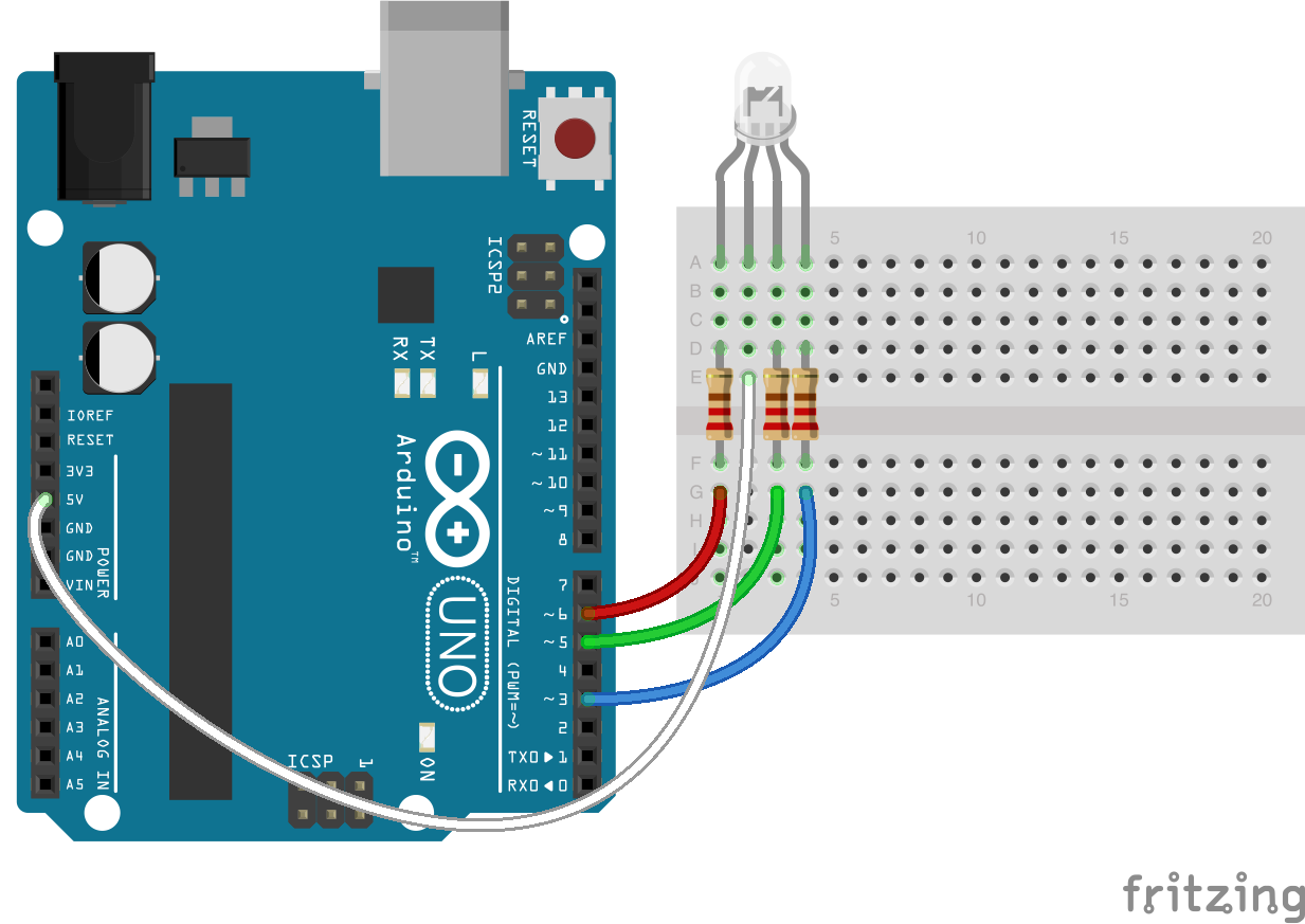
Should I connect rgb led for testing like that?

from control-surface.
tttapa
commented on May 24, 2024
I is the current, the arrow indicates the direction of conventional current flow.
The image looks fine, except that the black wire should be connected to the R pin.
from control-surface.
kentforth
commented on May 24, 2024
I'm an idiot=(
The problem was wiring. These chinese jumpers are awfull. I made my own jumpers from ethernet cable and all leds works fine!
Thank you Pieter for helping me!
from control-surface.
tttapa
commented on May 24, 2024
Glad to hear you got it working!
from control-surface.
Related Issues (20)
- Bankable::ManyAddresses::CCAbsoluteEncoder HOT 2
- Time Display does not work.
- Does it's support ESP32-S3/C3 via USB port? HOT 7
- Control Change Potentiometer Example doesn't compile for Teensy 4.1 HOT 1
- Compilation error: expected template-name before '<' token HOT 2
- Arduino UNO R4 support and testing HOT 3
- Arduino Yun HOT 2
- Trying to setVelocity for all notebutton values in mux with piezo device HOT 1
- External app/webpage to change CC and Channel values HOT 1
- Hi, I would like to see the USBMIDI_Interface adapted so that you can specify the fixed cablenumber. This would it make possible to use pipes and filters connecting serial ports with virtual usb ports
- Support for MCP23S17 SPI
- error: 'SelectorPC' does not name a type HOT 2
- Switching presets Roland FP-30X HOT 2
- TYPO IN DOCUMENTATION HOT 1
- Error running on M1 Mac Sonoma with Teensy 4.0 HOT 4
- Arduino Nano 33 BLE Support? HOT 3
- Пример CCIncrementDecrementButtons.ino HOT 10
- Select bank HOT 2
- MIDI-монитор-OLED HOT 3
- Arduino Giga R1 Wifi support HOT 2
Recommend Projects
-
 React
React
A declarative, efficient, and flexible JavaScript library for building user interfaces.
-
Vue.js
🖖 Vue.js is a progressive, incrementally-adoptable JavaScript framework for building UI on the web.
-
 Typescript
TypeScript is a superset of JavaScript that compiles to clean JavaScript output.
-
TensorFlow
An Open Source Machine Learning Framework for Everyone
-
Django
The Web framework for perfectionists with deadlines.
-
 Laravel
A PHP framework for web artisans
-
D3
Bring data to life with SVG, Canvas and HTML. 📊📈🎉
-
Recommend Topics
-
javascript
JavaScript (JS) is a lightweight interpreted programming language with first-class functions.
-
web
Some thing interesting about web. New door for the world.
-
server
A server is a program made to process requests and deliver data to clients.
-
Machine learning
Machine learning is a way of modeling and interpreting data that allows a piece of software to respond intelligently.
-
Visualization
Some thing interesting about visualization, use data art
-
Game
Some thing interesting about game, make everyone happy.
Recommend Org
-
Facebook
We are working to build community through open source technology. NB: members must have two-factor auth.
-
Microsoft
Open source projects and samples from Microsoft.
-
Google
Google ❤️ Open Source for everyone.
-
Alibaba
Alibaba Open Source for everyone
-
D3
Data-Driven Documents codes.
-
Tencent
China tencent open source team.
from control-surface.