The main inspiration for this project is from the movie Interstellar by Christopher Nolan. The movie features a blackhole called Gargantua that was rendered using Einstein's laws of General Relativity.
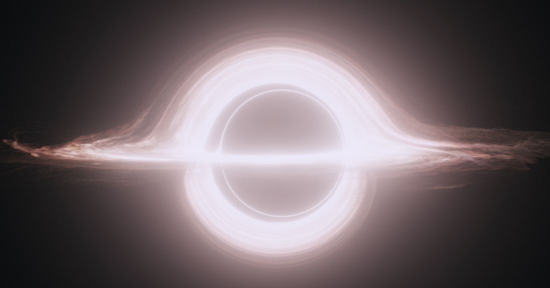
Gargantua A variant of the black-hole accretion disk seen in the film Interstellar. Credit: DNEG/Warner Bros. Entertainment Inc./CQG 32 065001
I wanted to try to recreate this at some level. I read through their technical paper on how they achieved this.
Paper: https://iopscience.iop.org/article/10.1088/0264-9381/32/6/065001#cqg508751f1
Their method was surprisingly simple. They followed a basic ray tracing algorithm. This algorithm starts with a point in space representing the camera. Then they cast rays out from the camera into the scene until a light source is reached. Each ray will define the color of a single pixel.

The difference from a normal ray tracer is that the rays will not follow straight lines. Because of the bending of spacetime that occurs near a massive object, the light rays will curve around it. This effect is called Gravitational lensing.

As the rays move through space they either hit the blackhole's event horizon, hit a light source, or end up being sent out into space. The first two situations are easy. The last takes a little more effort. My method was to first define a threshold where we decide a ray is no longer being effected by the blackhole significantly and we can approximate its path to being straight. I then extend the ray out to infinity and calculate its position on a 360 image of stars.

This is the main 360 image I used. It uses a projection technique called Equirectangular projection where latitude and longitude lines create squares that are equal throughout the image. This makes projecting from spherical coordinates to image coordinates straight forward.
- Graphics Programming
- File Systems
- Some memory management
The main part of this project is extremely calculation heavy but thankfully can be fully parallelized on the GPU to greatly increase speed, so GPU programming was essential to the feasibility of this project.
I needed to read in certain image file formats to gather the RGB data, the dimensions of the image and the number of channels. From here I can Manipulate the image and read and of its data. I also had the program output its own images, giving them unique names so I could have it create an animation while I step away from the computer.
A large portion of this was also allocated the correct amount of memory for the GPU, and from the operating system for saving data that is produced.
First I start by defining all of the arguments I need for the simulation. I can define things such as the camera's starting and ending positions, the position of the blackhole, the rotations of the camera, the size of the blackhole, accretion disk, and number of frames if you want to create an animation.
// Define arguments for the simulation
	CPU_Args->cameraInitPos = {0, 0, 2};
	CPU_Args->cameraFinPos = { 0, -10, 2 };
	CPU_Args->cameraDir = { -1, 0, 0 };
	CPU_Args->cameraUp = { 0, 0, 1 };
	CPU_Args->cameraRight = { 0, 1, 0 };
	CPU_Args->globalUp = { 0, 0, 1 };
	CPU_Args->bhPos = { -14, 0, 0 };
	CPU_Args->initPitch = 0.2;
	CPU_Args->finPitch = 0;
	CPU_Args->initYaw = 0;
	CPU_Args->finYaw = 0;
	CPU_Args->stepSize = 0.25;
	CPU_Args->bhRadius = 3;
	CPU_Args->rings = 30;
	CPU_Args->diskThickness = 5;
	CPU_Args->frames = 1;
	CPU_Args->disk = false;
Initializing the rays into the scene from the camera.
// Initialize the rays from the camera
void init_rays(Args_t* args) {
	printf("Initializing Rays\n");
	for (int i = 0; i < SCREEN_WIDTH; i++) {
		for (int j = 0; j < SCREEN_HEIGHT; j++) {
			rays[j * SCREEN_WIDTH + i].pos = args->cameraPos;
			rays[j * SCREEN_WIDTH + i].distTraveled = 0;
			Vec3f_t toPos;
			float nearScreen = 1.5;
			float aspectRatio = (float)SCREEN_WIDTH / SCREEN_HEIGHT;
			toPos.x = args->cameraDir.x * nearScreen
                + (-((float)i / SCREEN_WIDTH) + 0.5) * args->cameraRight.x * aspectRatio
                + (-((float)j / SCREEN_HEIGHT)) * args->cameraUp.x;
			toPos.y = args->cameraDir.y * nearScreen
                + (-((float)i / SCREEN_WIDTH) + 0.5) * args->cameraRight.y * aspectRatio
                + (-((float)j / SCREEN_HEIGHT)) * args->cameraUp.y;
			toPos.z = args->cameraDir.z * nearScreen
                + (-((float)i / SCREEN_WIDTH) + 0.5) * args->cameraRight.z * aspectRatio
                + (-((float)j / SCREEN_HEIGHT)) * args->cameraUp.z;

			float mag = sqrt(pow(toPos.x, 2) + pow(toPos.y, 2) + pow(toPos.z, 2));

			toPos.x = toPos.x / mag;
			toPos.y = toPos.y / mag;
			toPos.z = toPos.z / mag;

			rays[j * SCREEN_WIDTH + i].dir = toPos;

			rays[j * SCREEN_WIDTH + i].colored = false;
		}
	}
	printf("Rays initialized\n");
}
I then have it render the black hole. The paths of the rays are calculated using a numerical calculation technique called Runge-Kutta 4. This uses 4 sub steps based on the first derivative of the function you are trying to solve.

// Runge-Kutta 4 Numerical calulation substeps
		Result_t k1 =
            f(gpu_rays[j * SCREEN_WIDTH + i].pos,
            gpu_rays[j * SCREEN_WIDTH + i].dir, args->bhPos, args->stepSize, args->bhRadius);
		Result_t k2 =
            f(VecAdd(gpu_rays[j * SCREEN_WIDTH + i].pos, VecScale(k1.vec, args->stepSize / 2)),
            gpu_rays[j * SCREEN_WIDTH + i].dir, args->bhPos, args->stepSize, args->bhRadius);
		Result_t k3 =
            f(VecAdd(gpu_rays[j * SCREEN_WIDTH + i].pos, VecScale(k2.vec, args->stepSize / 2)),
            gpu_rays[j * SCREEN_WIDTH + i].dir, args->bhPos, args->stepSize, args->bhRadius);
		Result_t k4 =
            f(VecAdd(gpu_rays[j * SCREEN_WIDTH + i].pos, VecScale(k3.vec, args->stepSize)),
            gpu_rays[j * SCREEN_WIDTH + i].dir, args->bhPos, args->stepSize, args->bhRadius);

		gpu_rays[j * SCREEN_WIDTH + i].dir =
            VecScale(VecAdd(k1.vec, VecAdd(VecScale(k2.vec, 2),
            VecAdd(VecScale(k3.vec, 2), k4.vec))), (float) 1 / 6);

		float theta = (k1.angle + 2 * k2.angle + 2 * k3.angle + k4.angle) / 6;

		gpu_rays[j * SCREEN_WIDTH + i].pos =
            VecAdd(gpu_rays[j * SCREEN_WIDTH + i].pos,
            VecScale(gpu_rays[j * SCREEN_WIDTH + i].dir, args->stepSize));
What is
The rays are deflected by an angle so we need to find the angle.

Where

// First derivative of the position
__device__ Result_t f(Vec3f_t pos, Vec3f_t dir, Vec3f_t bhPos, float stepSize, float bhRadius) {
Vec3f_t toBHOld = VecAdd(bhPos, VecScale(pos, -1));
float rOld = VecMag(toBHOld);
float rho = VecMag(dir);
float ax = -dir.x * pos.x + dir.x * bhPos.x;
float ay = -dir.y * pos.y + dir.y * bhPos.y;
float az = -dir.z * pos.z + dir.z * bhPos.z;
float a = (ax + ay + az) / rho;
Vec3f_t perihelion = VecAdd(pos, VecScale(dir, a));
float b = VecMag(VecAdd(bhPos, VecScale(perihelion, -1)));
Vec3f_t futurePos = VecAdd(pos, VecScale(dir, stepSize));
Vec3f_t toBH = VecAdd(bhPos, VecScale(futurePos, -1));
float r = VecMag(toBH);
float dr = r - rOld;
float theta =
dr / (pow(rOld, 2) * sqrt((1 / pow(b, 2)) - (1 - bhRadius / rOld) * (1 / pow(rOld, 2))));
Vec3f_t normal = CrossProd(dir, toBH);
Result_t result = { Normalized(RodriguesFormula(dir, normal, theta)), theta };
return result;
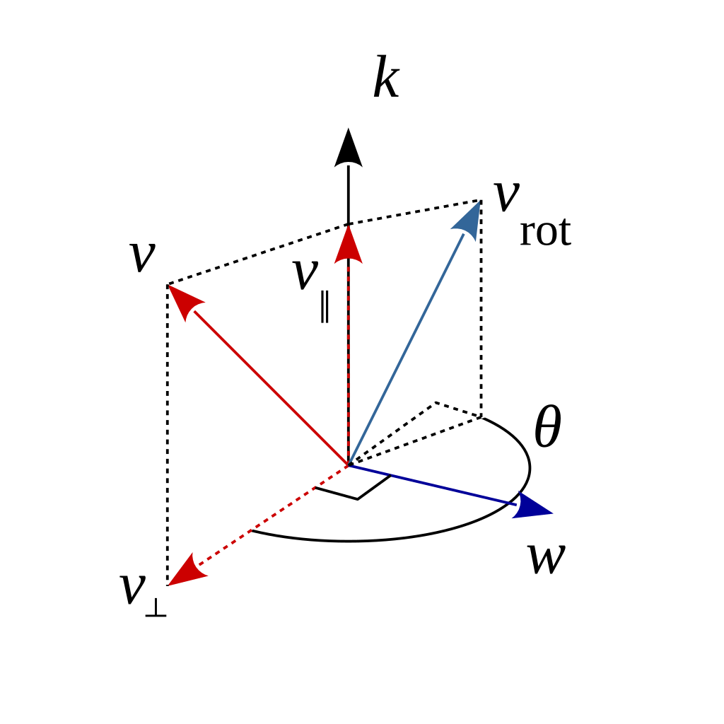
}I use the Rodrigues rotation formula to calculate the resulting vector after rotation.
Rodrigues Formula:

This process is iterated over until the rays either hit the blackhole, accretion disk, or the celestial sphere.
Then we have finally rendered an image. My first few images were not amazing. The projections were off. Notice the curve of the accretion disk here. This image is looking straight at the side of the blackhole so the disk should make a straight line, it does not. What is working is the ability to see the accretion disk above and below the blackhole. This is the expected behavior and shows us that the gravitational lensing is working.

I solved the projection issues so the disk is flat, then moved the camera slightly above the plane of the disk so that we can see the top of the disk. I also added rings to the accretion disk so the geometry is visible.

A closer view at a smaller step size.
.jpg)
Then I got the celestial sphere working and the accretion disk was no longer the coolest part.

This is using an equirectangular projection of the globe as my input.


.jpg)
A gif of the camera approaching the blackhole. Notice how the background changes.

Animation of the camera moving relative to the black hole.

