Turn your RC radio into a controller for your PC.
The default channel map aims at being usefull for 6 channel radios while exposing as much functionality as possible.
| Channel | Function |
|---|---|
| 1. | Stick R Y |
| 2. | Stick R X |
| 3. | Stick L Y (Y Rotation) |
| 4. | Stick L X (X Rotation) |
| 5. | Button 1, 2, 3 (Low, Mid, Max) |
| 6. | Z |
| 7. | Z rotation |
| 8. | Slider |
| 9. | Dial |
| 10. | Button 4, 5, 6 |
| 11. | Button 7, 8, 9 |
| 12. | Button 10, 11, 12 |
| 13. | Button 13, 14, 15 |
| 14. | Button 16, 17, 18 |
| 15. | Button 19, 20, 21 |
| 16. | Button 22, 23, 24 |
| 17. | Button 25 |
| 18. | Button 26 |
These are the function settins on my Futaba T16IZ. I ran out of switches for channels 15 and 16.
| Ch. | Function | Control |
|---|---|---|
| 1 | Aileron | J1 |
| 2 | Elevator | J2 |
| 3 | Throttle | J3 |
| 4 | Rudder | J4 |
| 5 | Gear | SE |
| 6 | Air Brake | LS |
| 7 | Aux 5 | RS |
| 8 | Aux 4 | LD |
| 9 | Aux 3 | RD |
| 10 | Aux 2 | SF |
| 11 | Aux 1 | SH |
| 12 | Aux 6 | SG |
| 13 | Aux 7 | SC |
| 14 | Camber | SB |
| 15 | Flap | N/A |
| 16 | Motor | N/A |
| DG1 | N/A | SD |
| DG2 | N/A | SA |
The circuit can be powered by the PICO VBUS and 3V3(out) pins when plugged in USB.
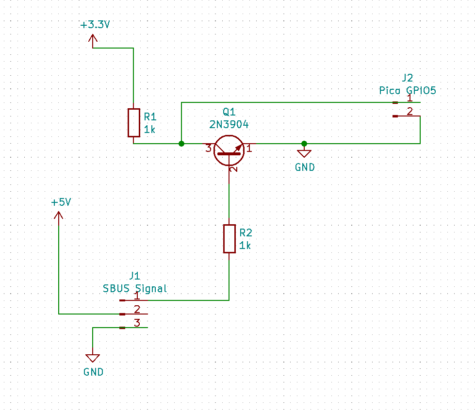
Futaba servo connector: | - + D |_
- SBUS + = 5v (VBus from PICO pin 40)
- SBUS - = GND (from pico PIN 3, 8, 13, 18, 23, 28 or 38)
- SBUS Data = Inverter input (CD74HCT14E pin 1)
- 1 = SBUS Data
- 2 = Inverted SBUS Data - Level Shifter Signal High side
- 7 = GND (from pico PIN 3, 8, 13, 18, 23, 28 or 38)
- 14 = 5v (VBus from PICO pin 40)
- HV1 = Inverted SBUS Data
- LV1 = Low level Inverted SBUS Data
- HV = 5v (VBus from PICO pin 40)
- LV = 3.3v (3V3(out) from PICO pin 36))
- GND = GND (from PICO PIN 3, 8, 13, 18, 23, 28 or 38)
- GP5 (pin7) = LV1 (3.3v low level inverted SBUS data)
- VBUS (pin40) = 5V
- 3v3(out) (pin 36)= 3.3v
- USB = Your PC :)
SBUS functionality inspired by https://github.com/fdivitto/sbus and https://github.com/BrushlessPower/SBUS2-Telemetry
We use UART1 and GPIO5 as RX pin.
You will need both a logic level converter to change the RX voltage to 3.3v and a logic inverter.
A Sparkfun logic level converter should work: https://www.sparkfun.com/products/12009
Signal coming from the receiver needs needs to be inverted. You can use a 7400 inverter like CD74HCT14E or a transistor based NOT gate as described here https://www.electronics-tutorials.ws/logic/logic_4.html
