Github io page link | |
The STEREOFOG dataset is available here: GDrive | tubcloud
The Supplement 1 PDF is available here: GDrive | tubcloud

nothing to show here
![]()
logo image attributions: U of U | DAAD
This repository documents a research project carried out at the Laboratory for Optical Nanotechnologies at the University of Utah under supervision of Prof. Rajesh Menon in Summer (July-September) 2023. It was funded as part of the RISE program by the German Academic Exchange Service (Deutscher Akademischer Austauschdienst (DAAD)).
Disclaimer: This work was supported by a fellowship of the German Academic Exchange Service (DAAD).
| real image | foggy image | reconstructed image |
|---|---|---|
 |
 |
 |

- stereofog
This project had three objectives:
- build a device capable of capturing paired images that depict the same scenery, one image with fog and the other without
- collect a dataset of paired images
- apply the pix2pix model developed at the University of California, Berkeley to the translation problem fog → no fog
- Autonomous driving
- Search & rescue (wildfires, home fires, etc.)
- Military
The project was carried out over the course three months, from July to September 2023. The following Gantt chart shows the project timeline:

click to expand
The device had to be able to:
- accomodate two cameras
- isolate the cameras from each other
- provide a fog chamber for one of the cameras
- trigger both cameras at the same time
The shift in perspective hailing from the distance the two cameras are set apart will be ignored. The further away the photographed scenes are, the less this will have an effect on the resulting images.
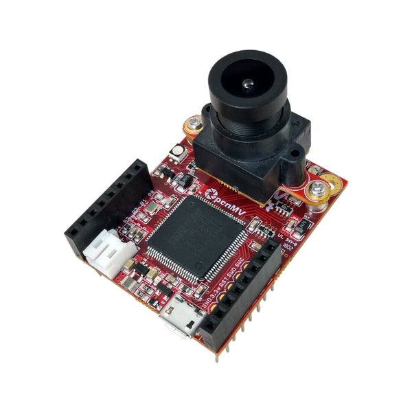
The two identical cameras used for this project had to be:
- programmable
- able to interface with other devices
- small & lightweight
- low power
Therefore, we chose to use the OpenMV H7 cameras for the task. The OpenMV IDE makes it easy to program the camera using python. They are able to receive input from their I/O pins as well as output user feedback using their LEDs.
In order to get exactly paired images from both cameras that are captured at the same time, it is necessary to introduce a common trigger. We used a lightweight Arduino board for this task. Any Arduino board should be capable of sending this trigger, but we used an Adafruit Feather 32u4 Radio that was available from an earlier project.

The board is connected to both cameras and sends a trigger signal to both cameras at the same time. The cameras are programmed to capture an image when they receive the trigger signal.

Image Attributions: Switches | Breadboard | Adafruit Feather board | OpenMV camera
Above is the wiring diagram for the project. Two switches are used to trigger both photos as well as videos. The photo trigger switch is connected to the Arduino board. It detects the state of the pin the switch is connected to and starts the recording loop. This means it sends a trigger signal to the cameras every second, as long as the switch is activated. At the same time, the onboard LED indicates this by blinking:
  if (trigger_switch_value == LOW) {
    digitalWrite(LED_BUILTIN, HIGH);
    digitalWrite(TOGGLE_PIN, HIGH);
    delay(650);
    digitalWrite(TOGGLE_PIN, LOW);
    digitalWrite(LED_BUILTIN, LOW);
    delay(650);
  }
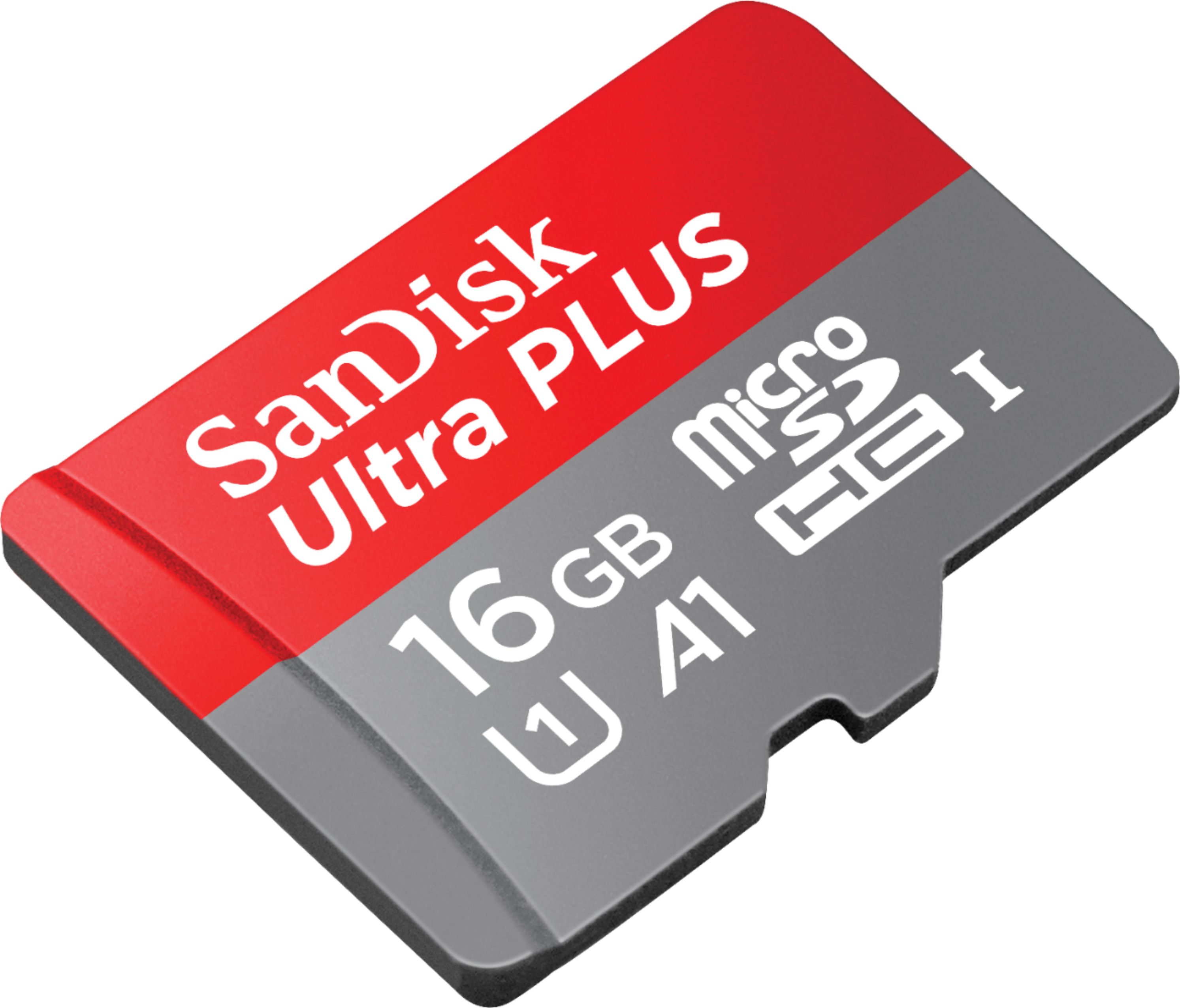
The total delay of 1.3s was necessary in order to leave the cameras with enough time to process the images. They were equipped with microSD cards with slightly different specifications, and below this threshold, the camera with the slower card would skip an image after a few frames, since it was still processing the previous image.
The entire Arduino code can be found in the Arduino script. In addition, the Arduino board is used to pass the 5V power supplied using a USB cable and a powerbank to the cameras.
The video trigger switch is connected directly to the cameras in order to avoid overhead introduced by the Arduino board.
Both OpenMV cameras are equipped with the exact same python code that listens to the two pins at which the input signals arrive. In case a video trigger signal is detected, the cameras instantly start recording a video. The video is stopped when the switch returns to the off position. The video is then saved to the microSD card as an .mjpeg file, numbered sequentially:
# Loop forever
while(True):

    if mode_pin.value() == 1:

        blue_led.on()

        m = mjpeg.Mjpeg("recorded_videos/"+ str(video_counter) + ".mjpeg")

        while mode_pin.value() == 1:
            clock.tick()
            m.add_frame(sensor.snapshot())
            #print(clock.fps())

        m.close(clock.fps())
        blue_led.off()

        video_counter += 1
In case no input signal is detected at the video trigger, the cameras listen to the photo trigger. When a signal is detected there, they capture an image, label it sequentially, save it to the microSD card and then wait for the current trigger signal to go away, as to avoid capturing multiple images on one trigger:
    else:
        # collect image if GPIO pin detects a HIGH signal
        if pin.value() == 1:


                img = sensor.snapshot()

                # toggle green LED after recording image to provide positive user feedback
                green_led.on()
                time.sleep_ms(100)
                green_led.off()

                # Saving the image
                img.save('/recorded_images/' + str(counter))
                counter += 1

                # Stop continuing until the pin value has gone to low again
                while pin.value() == 1:
                    pass # do nothing to wait for the trigger going away, to make sure only one image is collected per trigger
The entire python code for the cameras can be found in the respective script.

In order to stabilize the images while walking and ensure they are approximately level, a gimbal was used to hold the entire device. The gimbal used for this project was the Hohem iSteady Q. It is a lightweight single-axis gimbal that is able to hold a smartphone.
In order to be able to capture approximately the same image, the cameras had to be mounted as close together as possible. Simultaneously, the case must be able to hold the fog surrounding one camera while isolating the other camera from the influence of the fog, keeping all other conditions the same.
Therefore, both cameras are arranged side by side, inside separate chambers. The setup of the initial prototype put the box with the two cameras far above axis of rotation of the gimbal. The resulting torque to keep the construction level was too high in this configuration, causing the gimbal to shut off regularly.

The case was designed in Fusion 360. Some 3D printed files were printed using a Creality Ender 3 Pro, some on an Ultimaker S3. The front plate was lasercut on a CO2 laser cutter.


Initially, the following small handheld fogger was used:

For filling the device's fog chamber, its nozzle was inserted into the opening at the bottom of the chamber, while allowing air to escape through the opening at the top, inside the maintenance door. Since there was no perfect seal between the nozzle and the chamber, refilling took longer than necessary.
In the updated prototype, a new fogger with a plastic tube was used. This was directly ported into the chamber through a pneumatic fitting. This allowed for nearly lossless filling of the fog chamber.

| CAD design | physical prototype |
|---|---|
 |
 |
The following components are required for the device:
- 2x OpenMV H7 camera
- 1x Adafruit Feather board (or any other microcontroller capable of this task, i.e., any other microcontroller)
- 1x Hohem iSteady Q gimbal
- 2x Toggle switch (any latching switch that can be used to trigger the cameras)
- 1x Breadboard 30x70mm
- 2x Rubber stoppers
- Back box
- Front plate
- Front camera screw terminal
- Gimbal mount
- Gimbal bridge
- Hinge
- Lock body
- Lock catch
- Lock receptor
- Maintenance door with hinge
- Maintenance door brace
- Rear camera standoff
- Top plate
- Wire restraint
Several parts of the CAD model were adopted from different sources. They are attributed in the following:
| Part | Source | License |
|---|---|---|
| OpenMV camera | GrabCAD | unknown |
| Adafruit Feather board | Adafruit | MIT |
| Prototyping board | GrabCAD | unknown |
| Toggle switch | GrabCAD | unknown |
| DIN912 M3 25mm screw | 3Dfindit | unknown |
The models were either trained on a lab computer equipped with a dedicated GPU (NVIDIA GeForce GTX 970) and 64 GB of RAM or on the University of Utah's Center for High Performance Computing (CHPC) cluster. All models were trained for the default 200 epochs for the pix2pix model. The training time increased along with the size of the dataset. For the final model, the training time was around 20 hours.
descriptions on how to get up and running
click to expand
Clone the repository using git:
git clone https://github.com/apoll2000/stereofog.gitNavigate into the repository:
cd stereofogNext, an appropriate Python environment needs to be created. All code was run on Python 3.9.7. For creating the environment, either conda or pyenv virtualenv can be used.
The environment can be created using conda with:
conda create --name stereofog python=3.9.7Or using pyenv virtualenv with:
pyenv virtualenv 3.9.7 stereofogThen activate the environment with:
conda activate stereofogOr:
pyenv activate stereofogUsing pip, the required packages can then be installed. (for conda environments, execute
conda install pipbefore to install pip). The packages are listed in the requirements.txt and can be installed with:
pip install -r requirements.txtIn case you want to install them manually, the packages include:
numpytorchopencv-pythonmatplotlib- ...
It is important that you specify the right torch version if you would like to use your CUDA-enabled GPU to train the model, which will drastically reduce training time. See the PyTorch website for more information.
The dataset is currently being hosted here: TUBCloud. Depending on the further development of the project, this might not be the final storing location.
Place the stereofog_images folder into the datasets folder of the repository:
-- datasets
    |-- stereofog_images
        |-- 2023-08-03-04
            |-- A
                |-- 01-04_08_23__1.bmp
                |-- 01-04_08_23__2.bmp
                |-- ...
            |-- B
                |-- 01-04_08_23__1.bmp
                |-- 01-04_08_23__2.bmp
                |-- ...
|-- ...The dataset needs to be prepared for training. This includes transforming the folder structure into one compatible with the pix2pix framework and splitting the dataset into training, validation and testing sets. It can be performed using the following command:
python preprocess_stereofog_dataset.py --dataroot path/to/datasetThe model training can be started using the following command:
python train.py --dataroot path/to/dataset --name name_of_model --model pix2pix --direction BtoA --gpu_ids 0python test.py --dataroot path/to/dataset --direction BtoA --model pix2pix --name name_of_modelAmple information on the training and testing process and their parameters can be found on the pix2pix GitHub page.
This GitHub page includes several helper scripts to perform different actions like hyperparameter tuning or epoch visualization.
These are: Preprocessing:
preprocess_stereofog_dataset.pyHyperparameter tuning:hyperparameter_dropoutRate.pyhyperparameter_GAN.pyhyperparameter_init_type.pyhyperparameter_lr_policy.pyhyperparameter_n_layers_D.pyhyperparameter_netD.pyhyperparameter_netG.pyhyperparameter_ngf_ndf.pyhyperparameter_normalization.pyhyperparameter_Res9AndMore.pyhyperparameter_supertraining.pyVisualization:plot_model_results.pyevaluate_model_group.py
click to expand
At the beginning of the project, we experimented with synthetic datasets in combination with the pix2pix model. The datasets used were based on the Cityscapes dataset as well as on images derived from the CARLA simulator. The fog simulations generally work either by directly using a depth map that is available for each particular image, or by using the left and right images to calculate the depths in the images, thus reconstructing this depth map. This depth map helps in estimating how strongly the fog affects different parts of the image.
The datasets in the following are semi-synthetic, meaning that they work with real images, to which the fog has been added synthetically. A disadvantage of this method is that the depth map is never perfect, which can lead to artifacts in the fogged images.
In cooperation with the researchers Georg Volk and Jörg Gamerdinger from the University of Tübingen, Germany, we trained a model on synthetic data generated for their paper "Simulating Photo-realistic Snow and Fog on Existing Images for Enhanced CNN Training and Evaluation".
Another dataset taken into consideration was the Foggy Cityscapes dataset from the paper "Semantic Foggy Scene Understanding with Synthetic Data" by Sakaridis et al.. The dataset was created by the Computer Vision Lab of ETH Zürich, Switzerland.
The following dataset was created entirely synthetically. The original images were rendered using a driving simulator, which generated the matching perfect depth maps as well. This way, the fogged images do not show any artifacts.
This dataset was created by the researchers Georg Volk and Jörg Gamerdinger from the University of Tübingen, Germany, using the same technique from the paper "Simulating Photo-realistic Snow and Fog on Existing Images for Enhanced CNN Training and Evaluation". It is based on the CARLA simulator.
description & details of the collected dataset
ML results on dataset
Looking through the images in the dataset, you will notice that it was mostly avoided to face the cameras directly at the sun (which was shining almost every day in the hot and dry summer of Salt Lake City). This was due to a limitation of the OpenMV H7 cameras used to capture the images. Their dynamic range is limited and they tend to be unable to resolve the high dynamic range when facing the sun directly.
| original | fogged |
|---|---|
 |
 |
The cameras were used in spite of this issue because of their advantages in programmability, connectivity and compactness.
As just mentioned, the images show almost exclusively sunny scenes. This is due to them being mostly collected during August, which is the clearest month of the year in Salt Lake City, with the sky being clear around 78% of the time. The few times it was raining, the camera was not used to avoid damage to the electronics.
The code is licensed under the BSD 3-Clause License, available under CODE_LICENSE. -> this is taken from pyramid pix2pix
The parts of the code that were adopted from the pix2pix project are licensed under ... MAKE SURE NOT TO VIOLATE PIX2PIX BSD LICENSE HERE
The dataset is licensed under the Creative Commons Attribution 4.0 International License, available under DATASET_LICENSE.
-> or should this be CC-BY-NC (non-commercial?)
The hardware is licensed under the CERN Open HArdware License v2 - Weakly Reciprocal (CERN-OHL-W v2), available under HARDWARE_LICENSE.
If you use the dataset or any of the code in this repository created by us, please cite the following paper:
@misc{pollak2023stereofog,
      title={STEREOFOG -- Computational DeFogging via Image-to-Image Translation on a real-world Dataset},
      author={Anton Pollak and Rajesh Menon},
      year={2023},
      eprint={2312.02344},
      archivePrefix={arXiv},
      primaryClass={cs.CV}
}
- [1]:
click to expand
We conducted a study on how quickly the fog decays in order to know better how often it needs to be replenished. This was done by filling the fog chamber, letting the fog decay and filming the entire decay using both of the cameras. The resulting video of the fogged camera was analyzed by calculating the Variance of the Laplacian of each frame as a metric for the intensity of the fog. You can see that after about 5 minutes, the fog intensity becomes quite low.


