Verilog HDL code for combinational lock on FPGA.
Article: https://habr.com/ru/post/537042/
Here we will describe the realization of combinational lock on Verilog hardware description language (HDL). These Verilog HDL files will describe the system architecture of the combinational lock.
We will write each Verilog HDL module in its own file for simplicity of reading and debugging the code.
The final project will contain this list of Verilog HDL files:
- anode_control.v
- bcd_control.v
- bcd_to_cathodes.v
- button_debouncer.v
- clock_divider.v
- data_saver.v
- increase_digit.v
- refresh_counter.v
- shift_anode.v
- show_manager.v
- state_indicator.v
- state_manager.v
- top.v
Next, we will describe the purpose and action of each of these files. The order of files will be from abstract to more concrete.
Since in the combinational lock we need to have an ability to enter data, password, etc., we need to have several different states in which the board will perform different functions. In common programming languages, we could make several consecutive calls to the corresponding functions wrapped in while(true), but in Verilog HDL we describe the architecture of the system, so "function calls" cannot be executed here. We conclude that we must somehow tell the system when to do certain actions. The state register can help us with this, which will tell other parts of the system what to do now.
To control register state, we will create a module state_manager. This module synchronizes other parts of the system by the variable state, describes what state will be next, and under what conditions state will change.
Input button_next is used to move to the next stage if conditions are satisfactory.
Inputs digitX_showing (entered passcode) and digitX_password are used on the passcode check stage.
Output state is a register, that synchronizes other parts of the program.
The module has always block which is executed every time button_next is clicked. Code inside always block selects next state and change variable state. At state 3, the correctness of the entered passcode is additionally checked. If it is not correct, the state is not changed.
We need to memorize data and password, therefore we create module data_saver which will do this.
This module will allow us to save registers from some inputs. We will save there passcode and data.
Input state is used to check if the module now should save data.
Input state_save is a parameter, which denotes the state on which we should save data.
Inputs digitX_insertdata are wires for digits, which we want to save.
Outputs digitX_data are registers where saved values from input digits will be stored.
In the always block it check state and if it equal to save_state, it saves input digits to registers.
Since we want to display different data from different registers (e.g. input data or saved data) on the same display, but segments on LED are just wires, each of which could be connected only to one register, we need to have some registers which will be "unite" those different registers, that is, equate to registers when their time teaches. We will perform the switch of the "unite" register in the module show_manager.
This module selects, according to the state, a pack of digits with position_pointer which will be displayed on LED among different packs.
Input state is needed to select actual digits.
Input button_increase is used to update digits when some of them increased.
Inputs position_pointer_insertdata, position_pointer_insertnewpass and position_pointer_insertpass are pointers for states of insertion data, creation passcode and insertation passcode accordingly.
Inputs digitX_insertdata, digitX_insertnewpass, digitX_insertpass and digitX_data are digits for same states as pointers plus state of data showing.
Output position_pointer is a register that is used to show on LED during editing which digit is selected to be increased.
Outputs digitX are registers that denote digits that are displaying on LED.
In the always block it checks using the case block which digits and position pointer should be showed and put them to the registers of showing data: digitX and position_pointer.
To show the user which state is now, we will display it on indicators. Manage of indication will be in the state_indicator module.
Input state is used to select which indicator will be on. It should be connected
Output lights is used to show to the user which state the combinational lock is. It should be connected to light indicators.
Module in always block turns on the corresponding indicator for the current state and turns off others (note that 0 corresponds to on and 1 — to off). The state is checked in case block.
This module increases selected by position_pointer digit by one when the user presses the button. Part of number modifying.
Input button_increase is a control button to increase digit. It should be connected to some button.
Input position_pointer shows which digit is selected.
Inputs state_need and state are used to activate functional when state is satisfy state_need, and deactivate when not.
Outputs digitXreg are registers that contain digits for the module's state.
Every time when button_increase clicked digit corresponding to position_pointer increases by one, if state satisfy state_need.
This module shifts position_pointer by one after clicking shift_button. Part of number modifying.
Input shift_button is control button to shift position_point.
Inputs state_need and state are used to activate functional when state is satisfy state_need, and deactivate when not.
Output position_pointer is a register that denotes the selected digit.
Every time when shift_button clicked position_pointer increases by one, if state satisfy state_need.
Unfortunately, FPGA plate designers didn't implement auto digit to cathode (sticks and points on the LED display) signals translator, we can not just execute some magic command print as in Python, so we need to perform translation, as well as other steps to display data, by ourselves.
In the bcd_to_cathodes module we perform digit to cathode signals translation of digit data: digit itself (sticks) and, if the current digit is selected, pointer (dot) for it. There happens digit displaying.
Input digit contains a value to be translated.
Input position_pointer_now shows is current digit is selected.
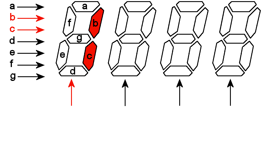
Output cathode are registers with translated to cathode signals digit. Current translation work for following order of cathodes cathode[0] -> A, cathode[1] -> B... cathode[7] -> DP (see picture below). Should be connected to cathodes on the FPGA plate.

In the first always block every time when position_pointer_now changes, cathode signal corresponding to point below digit updates respectively. In the second always block after every change of digit cathode signals corresponding to sticks turns in such a way that displaying the number on LED will be equal to the digit value.
Unfortunately (again), the designers of the 7-segment display made not separate pins for the cathodes of each anode, but common to all anodes, apparently for the sake of saving space. Therefore, different numbers cannot be displayed simultaneously on different anodes. But we can do this artificially, displaying the numbers on each anode separately (see the gif animation below), switching between them so quickly that the image on each anode does not have time to fade out. So, we will use this approach in this module.
In module anode_control we sequentially switch on anodes.
Input refreshcounter is synchronizing iterator which digit is displaying.
Output anode is an 8-bit register, where every bit corresponds to on (0) or off (1) of the anode.
always block executes after every iteration of refreshcounter and turn on corresponding to iteration anode.
Since we already have an iterational anode activator, we need to implement digit choosing for the current iteration. In the bcd_control module we do digit choosing and check if the current digit is selected (for point drawing).
Input state is used to check if position_pointer does make sense to show now.
Inputs digitX are digits which we display. From them we select current.
Input position_pointer is the number of digit that is selected.
Input refreshcounter is synchronizing iterator which digit is displaying.
Output ONE_DIGIT is the value of the current digit.
Output position_pointer_now is bool value is current digit is selected.
In always block after every change of iterator refreshcounter we update current displaying value ONE_DIGIT and position_pointer_now (for position_pointer_now we additionally check if on this state is "editable", if it is not, so we do not need to show it).
In the module refresh_counter we implement a synchronizing iterator for digits displaying.
Input refresh_clock is the system clock. In our case, it is a modified clock (later we will see why).
Output refreshcounter is an iterator that can have only 8 different values — one per digit.
In always block after every clock of refresh_clock iterator refreshcounter goes to the next digit by increasing by zero (note, that if refreshcounter has overflow, it ignores it and drop out overflow part, so after the 8th digit, iterator goes to the 1st digit).
It would seem that all the steps to display a number on the LED display have been completed, and everything should work ... but if we try to display any 8 digits with the existing system, unfortunately, we are faced with a harsh reality, and nothing will work, the numbers on the display will be blurry. The fact is that the standard frequency of 50 MHz is too high, some of the signals on the LED display will not arrive on time. Therefore, we need to lower the clock frequency for the digit display modules.

In module clock_divider we create a new slow clock.
Input clk is the original clock.
Output divided_clk is the slow clock.
In the module we have parameter div_value = 50 MHz / (2 * desired Frequency) - 1. divided_clk inverted every (div_value + 1)th activation of clock. Thus, frequency of divided_clk = 50 MHz / (2 * (div_value + 1)) = 1000 Hz (in our case).
All the main modules for the operation of the combination lock are ready. However, if we try to run them all together on an FPGA board, we will run into the problem that sometimes a button press is counted as multiple. We don't like this, so we'll make a module button debouncer, that will deal with it.
We will consider only those inputs and outputs, that we will use. For a detailed description of the module see there: http://www.labfor.ru/articles/debouncer_verilog.
Input clk_i is the system clock.
Input sw_i is a button that we want to debounce.
Output sw_down_o is a register, that equal to posedge of the button.
Detailed description of the module see there: http://www.labfor.ru/articles/debouncer_verilog.
Finally, we need to implement a top-level module. There we will "call" all modules that we want to use and descript logic between system elements.
The project authors are Shevchenko Makar Ilyich, Murashko Artem Maximovich, Chernitsa Artem Alexandrovich.
Thanks to: Burmyakov Artem, Tormasov Alexander, Ostankovich Vladislav, Muhammad Fahim, Voronov Artem, Innopolis University.
