![]()
![]()
![]()
ESP32_Display_Panel is an Arduino library designed for driving display screens using ESP SoCs. It can be used not only for developing various Espressif development boards but also for custom board development.
ESP32_Display_Panel encapsulates various components from the Espressif Components Registry. It is developed based on arduino-esp32 and can be easily downloaded and integrated into the Arduino IDE.
- ESP32_Display_Panel
The block diagram of ESP32_Display_Panel is shown in the figure below, it primarily includes the following features:
- Supports various Espressif development boards.
- Supports custom board.
- Supports multiple types of drivers, including Bus, LCD, Touch, Backlight.

| Picture | Name | LCD Bus | LCD Controller | Touch Bus | Touch Controller |
|---|---|---|---|---|---|
 |
ESP32-C3-LCDkit | SPI | GC9A01 | - | - |
 |
ESP32-S3-Box | SPI | ILI9342 | I2C | TT21100 |
 |
ESP32-S3-Box-3 | SPI | ILI9342 | I2C | GT911 |
 |
ESP32-S3-Box-3(beta) | SPI | ILI9342 | I2C | TT21100 |
 |
ESP32-S3-Box-Lite | SPI | ST7789 | - | - |
 |
ESP32-S3-EYE | SPI | ST7789 | - | - |
 |
ESP32-S3-Korvo-2 | SPI | ILI9342 | I2C | TT21100 |
 |
ESP32-S3-LCD-EV-Board | 3-wire SPI + RGB | GC9503 | I2C | FT5X06 |
 |
ESP32-S3-LCD-EV-Board-2 | RGB | ST7262E43 | I2C | GT1151 |
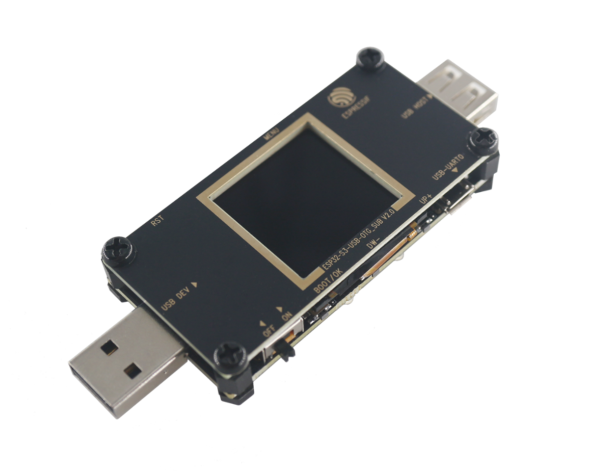 |
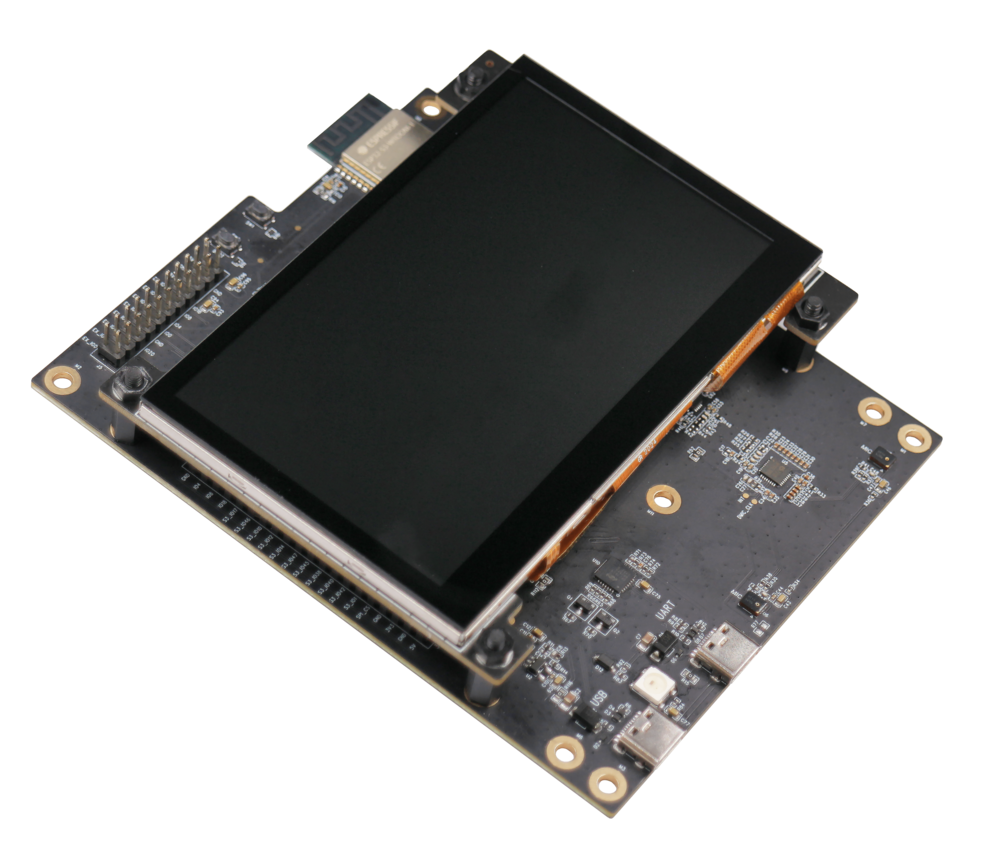
ESP32-S3-USB-OTG | SPI | ST7789 | - | - |
| Bus | Version |
|---|---|
| I2C | - |
| SPI | - |
| 3-wire SPI + RGB | v1.0.0 |
| LCD Controller | Version |
|---|---|
| ILI9341 | 1.0.2 |
| GC9503 | 1.0.0 |
| GC9A01 | 1.0.1 |
| ST7262 | - |
| ST7789 | - |
| ST7796 | 1.0.0 |
| Touch Controller | Version |
|---|---|
| esp_lcd_touch | 1.0.4 |
| CST816S | 1.0.3 |
| FT5x06 | 1.0.5~1 |
| GT1151 | 1.0.5~1 |
| GT911 | 1.0.7~1 |
| TT21100 | 1.0.7~1 |
| STMPE610 | 1.0.6 |
| Name | Version |
|---|---|
| ESP32_Display_Panel | v0.0.2 |
| ESP32_IO_Expander | >= v0.0.1 |
| arduino-esp32 | >= v2.0.9, < 3.0.0 |
For information on how to use the library in the Arduino IDE, please refer to the documentation for Arduino IDE v1.x.x or Arduino IDE v2.x.x. The path of Arduino libraries folder can be found or changed at File > Preferences > Settings > Sketchbook location.
Here are some examples of using ESP32_Display_Panel. To access them in the Arduino IDE, navigate to File > Examples > ESP32_Display_Panel. If there is no ESP32_Display_Panel option, please check if the library has been installed correctly and select an esp32 board first.
- Draw Color Bar: This example demonstrates how to draw simple color bar.
- Read Touch Point: This example demonstrates how to read touch point.
To configure LVGL (v8.3.x), please see here for more details.
- Porting: This example demonstrates how to port LVGL.
To port the Squareline project (v1.3.x), please see here for more details.
- Porting: This example demonstrates how to port the Squareline project.
- WiFiClock: This example implements a simple Wi-Fi clock demo.
The following provides a comprehensive guide on how to use ESP32_Display_Panel.
ESP32_Display_Panel has its own configuration file called ESP_Panel_Conf.h. After installing ESP32_Display_Panel, follow these configuration steps:
-
Navigate to the directory where Arduino libraries are installed (The path of libraries folder can be found or changed at
File>Preferences>Settings>Sketchbook location). -
Navigate to the
ESP32_Display_Panelfolder, copyESP_Panel_Conf_Template.hand place the copy outside theESP32_Display_Panelfolder at the same directory level. Then rename the copied file asESP_Panel_Conf.h. -
Finally, the layout of the Arduino Libraries folder with
ESP_Panel_Conf.happear as follows:Arduino |-libraries |-ESP32_Display_Panel |-other_lib_1 |-other_lib_2 |-ESP_Panel_Conf.h -
Please refer to the Supported Boards List to check if the current board is compatible. If it is compatible, please navigate to the "For Supported Boards" section; Otherwise, navigate to the "For Unsupported Boards" section.
-
Open
ESP_Panel_Conf.hfile. First, set the macroESP_PANEL_USE_SUPPORTED_BOARDto1(default is1). Then, according to the name of your target development board, uncomment the macro definitions in the formatESP_PANEL_BOARD_<NAME>below, -
The following code takes ESP32_S3_BOX development board as an example:
...
// #define ESP_PANEL_BOARD_ESP32_C3_LCDKIT
#define ESP_PANEL_BOARD_ESP32_S3_BOX
// #define ESP_PANEL_BOARD_ESP32_S3_BOX_LITE
...
-
After that, navigate to the "Use APIs" section to use the library in the sketch.
Since ESP32_Display_Panel library can only utilize the internally supported drivers, please ensure that the LCD, Touch, and Bus for the custom board are present in the list of Supported Drivers. Then follow the steps below to configure the library:
-
Open
ESP_Panel_Conf.hand set the macroESP_PANEL_USE_SUPPORTED_BOARDto0, as shown below:#define ESP_PANEL_USE_SUPPORTED_BOARD (0)
-
Modify the values of other macros as needed. They represent parameters that can be adjusted for LCD, Touch, and other devices initialization.
-
Here are some important macros for the LCD:
/* Set to 0 if not using LCD */
#define ESP_PANEL_USE_LCD           (0)

/**
 * LCD controller name. Choose one of the following:
 *      - ILI9341
 *      - GC9503, GC9A01
 *      - ST7262, ST7789, ST7796
 */
#define ESP_PANEL_LCD_NAME          ST7789

/* LCD resolution in pixels */
#define ESP_PANEL_LCD_H_RES         (320)
#define ESP_PANEL_LCD_V_RES         (240)

/* LCD Bus Settings */
/**
 * If set to 1, the bus will skip to initialize the corresponding host. Users need to initialize the host in advance.
 * It is useful if other devices use the same host. Please ensure that the host is initialized only once.
 */
#define ESP_PANEL_LCD_BUS_SKIP_INIT_HOST        (0)
/**
 * LCD bus type. Choose one of the following:
 *      - 0: I2C (not supported yet)
 *      - 1: SPI
 *      - 2: I80 (not supported yet)
 *      - 3: RGB
 */
#define ESP_PANEL_LCD_BUS_TYPE      (1)
/**
 * LCD bus parameters.
 *
 * Please refer to https://docs.espressif.com/projects/esp-idf/en/latest/esp32s3/api-reference/peripherals/lcd.html for details.
 */
#define ESP_PANEL_LCD_BUS_HOST_ID           (1)
...

/* LCD Color Settings */
/* LCD color depth in bits */
#define ESP_PANEL_LCD_COLOR_BITS    (16)
/*
 * LCD Color Space. Choose one of the following:
 *      - 0: RGB
 *      - 1: BGR
 */
#define ESP_PANEL_LCD_COLOR_SPACE   (0)
#define ESP_PANEL_LCD_INEVRT_COLOR  (0)

/* LCD Transformation Flags */
#define ESP_PANEL_LCD_SWAP_XY       (0)
#define ESP_PANEL_LCD_MIRROR_X      (0)
#define ESP_PANEL_LCD_MIRROR_Y      (0)

/* LCD Other Settings */
/* IO num of RESET pin, set to -1 if not use */
#define ESP_PANEL_LCD_IO_RST        (-1)
#define ESP_PANEL_LCD_RST_LEVEL     (0)
-
Here are some important macros for the LCD Touch:
/* Set to 0 if not using LCD touch */
#define ESP_PANEL_USE_LCD_TOUCH     (0)

/**
 * LCD Touch IC name. Choose one of the following:
 *      - CST816S
 *      - FT5x06
 *      - GT1151, GT911
 *      - TT21100
 *      - STMPE610
 */
#define ESP_PANEL_LCD_TOUCH_NAME            TT21100

/* LCD Touch resolution in pixels */
#define ESP_PANEL_LCD_TOUCH_H_RES           (ESP_PANEL_LCD_H_RES)
#define ESP_PANEL_LCD_TOUCH_V_RES           (ESP_PANEL_LCD_V_RES)

/* LCD Touch Bus Settings */
/**
 * If set to 1, the bus will skip to initialize the corresponding host. Users need to initialize the host in advance.
 * It is useful if other devices use the same host. Please ensure that the host is initialized only once.
 */
#define ESP_PANEL_LCD_TOUCH_BUS_SKIP_INIT_HOST  (0)
/**
 * LCD touch bus type. Choose one of the following:
 *      - 0: I2C
 *      - 1: SPI
 */
#define ESP_PANEL_LCD_TOUCH_BUS_TYPE            (0)
/**
 * LCD touch bus parameters.
 *
 * Please refer to https://docs.espressif.com/projects/esp-idf/en/latest/esp32s3/api-reference/peripherals/lcd.html for details.
 */
#define ESP_PANEL_LCD_TOUCH_BUS_HOST_ID     (0)
...

/* LCD Touch Transformation Flags */
#define ESP_PANEL_LCD_TOUCH_SWAP_XY         (0)
#define ESP_PANEL_LCD_TOUCH_MIRROR_X        (0)
#define ESP_PANEL_LCD_TOUCH_MIRROR_Y        (0)

/* LCD Touch Other Settings */
#define ESP_PANEL_LCD_TOUCH_IO_RST          (-1)
#define ESP_PANEL_LCD_TOUCH_IO_INT          (-1)
#define ESP_PANEL_LCD_TOUCH_RST_LEVEL       (0)
#define ESP_PANEL_LCD_TOUCH_INT_LEVEL       (0)
-
Here are some important macros for the backlight:
#define ESP_PANEL_USE_BL                    (0)

/* IO num of backlight pin */
#define ESP_PANEL_LCD_IO_BL                 (45)

/* If the backlight is on when high level, set to 1; otherwise to 0 */
#define ESP_PANEL_LCD_BL_ON_LEVEL           (1)

/* Set to 1 if use PWM for backlight brightness control. */
#define ESP_PANEL_LCD_BL_USE_PWM            (0)

/**
 *  Backlight LEDC Parameters.
 *
 *  Please refer to https://docs.espressif.com/projects/esp-idf/en/latest/esp32s3/api-reference/peripherals/ledc.html for details.
 */
#define ESP_PANEL_LCD_BL_PWM_TIMER          (0)
...
- After configuring the
ESP_Panel_Conf.hfile, please navigate to the "Use APIs" section to check the functions provided by ESP32_Display_Panel.
The following codes show the usage of common APIs:
#include <ESP_Panel_Library.h>

// Create an ESP_Panel object
ESP_Panel *panel = new ESP_Panel();

// Initialize and start the ESP_Panel object
panel>init();
panel>begin();

// Get the LCD object and operate it
panel>getLcd()>setCallback(callback, NULL);
panel>getLcd()>drawBitmap(0, 0, width, height, color);

// Get the LCD touch object and operate it
panel>getLcdTouch()>readData();
bool touched = panel>getLcdTouch()>getTouchState();
if(touched) {
    TouchPoint point = panel>getLcdTouch()>getPoint();
    Serial.printf("Touch point: x %d, y %d\n", point.x, point.y);
}

// Get the backlight object and operate it
panel>getBacklight()>on();
panel>getBacklight()>off();
panel>getBacklight()>setBrightness(50);

// Release the ESP_Panel object
delete panel;
Below are recommended configurations for developing GUI applications on various development boards. These settings can be adjusted based on specific requirements.
Go to the Tools in Arduino IDE to configure the following settings:
| Supported Boards | Selected Board | PSRAM | Flash Mode | Flash Size | USB CDC On Boot | Partition Scheme |
|---|---|---|---|---|---|---|
| ESP32-C3-LCDkit | ESP32C3 Dev Module | Disabled | QIO | 4MB (32Mb) | Enabled | Default 4MB with spiffs |
| ESP32-S3-Box | ESP32-S3-Box | - | - | - | - | 16M Flash (3MB) |
| ESP32-S3-Box-3 | ESP32S3 Dev Module | OPI | QIO 80MHz | 16MB | Enabled | 16M Flash (3MB) |
| ESP32-S3-Box-3(beta) | ESP32S3 Dev Module | OPI | QIO 80MHz | 16MB | Enabled | 16M Flash (3MB) |
| ESP32-S3-Box-Lite | ESP32-S3-Box | - | - | - | - | 16M Flash (3MB) |
| ESP32-S3-EYE | ESP32S3 Dev Module | OPI | QIO 80MHz | 8MB | Enabled | 8M with spiffs |
| ESP32-S3-Korvo-2 | ESP32S3 Dev Module | OPI | QIO 80MHz | 16MB | Disabled | 16M Flash (3MB) |
| ESP32-S3-LCD-EV-Board | ESP32S3 Dev Module | OPI | QIO 80MHz | 16MB | See Note 1 | 16M Flash (3MB) |
| ESP32-S3-LCD-EV-Board-2 | ESP32S3 Dev Module | OPI | QIO 80MHz | 16MB | See Note 1 | 16M Flash (3MB) |
| ESP32-S3-USB-OTG | ESP32-S3-USB-OTG | - | - | - | - | 8M with spiffs |
Note:
-
"USB CDC On Boot" should be enabled according to the using port:
- Disable this configuration if using UART port, enable it if using USB port.
- If this configuration is different in the previous flashing, should enable
Erase All Flash Before Sketch Uploadfirst, then can disable it after flashing.
-
To see the more output log, please set
Core Debug LeveltoInfoor a lower level.
LVGL also has its own configuration file called lv_conf.h. After installing lvgl (v8.3.x), follow these configuration steps:
-
Navigate to the directory where Arduino libraries are installed (The path of libraries folder can be found or changed at
File>Preferences>Settings>Sketchbook location). -
Navigate to the
lvglfolder, copylv_conf_template.hand place the copy outside thelvglfolder at the same directory level. Then rename the copied file aslv_conf.h. -
Finally, the layout of the Arduino Libraries folder with
lv_conf.happear as follows:Arduino |-libraries |-lv_conf.h |-lvgl |-other_lib_1 |-other_lib_2 -
Open
lv_conf.hand change the first#if 0to#if 1to enable the content of the file. -
Set the other configurations according to the requirements, here are some common configurations:
#define LV_COLOR_DEPTH          16  // Normally we just use 16-bit color depth (RGB565),
                                    // but 24-bit color depth (RGB888) can also be supported by setting it to `32`
#define LV_COLOR_16_SWAP        1   // Set it to `0` if using RGB LCD (e.g. ESP32-S3-LCD-Ev-Board/-2)
#define LV_MEM_CUSTOM           1
#define LV_MEMCPY_MEMSET_STD    1
#define LV_TICK_CUSTOM          1
#define LV_ATTRIBUTE_FAST_MEM   IRAM_ATTR   // Get higher performance but take up more SRAM
#define LV_FONT_MONTSERRAT_N    1  // Enable all the internally used fonts (`N` should be replaced by the font size)
-
For more information, please refer to LVGL document.
It is convenient to design beautiful UI using Squareline Studio through graphical editing. To use UI source files exported from Squareline in the Arduino IDE, follow these steps:
-
First, create a new project in Squareline Studio. Go to
Create>Arduino, selectArduino with TFT-eSPIas the project template. On the right side, configure project settings based on the LCD properties of the target development board, likeResolutionandColor depth. Finally, click theCreatebutton to create the project. -
For existing projects, please click on
File>Project Settingsin the navigation bar. SetBoard GrouptoArduino,BoardtoArduino with TFT-eSPI, and configure theDISPLAY PROPERTIESbased on the target development board's LCD properties in the same section. Finally, click theSavebutton to save project settings. -
Once finished UI design and set the export path, click the navigation bar's
Export>Create Template ProjectandExport UI Filesto export the project and UI source files. The layout of project directory should appear as follows:Squareline Project |-libraries |-lv_conf.h |-lvgl |-readme.txt |-TFT_eSPI |-ui |-README.md |-ui -
Finally, copy the
lv_conf.h,lvgl, anduifrom thelibrarieswithin the project directory to the Arduino libraries directory (The path of libraries folder can be found or changed atFile>Preferences>Settings>Sketchbook location). If just want to use a locally installedlvgl, please skip copyinglvglandlv_conf.h, then refer steps to configure LVGL. The final layout should appear as follows:Arduino |-libraries |-ESP32_Display_Panel |-ESP_Panel_Conf.h |-lv_conf.h |-lvgl |-ui |-other_lib_1 |-other_lib_2

