| Team Member | Role |
|---|---|
| Ryan Anderson | Team Lead, Back-end, Front-end |
| Jose Torres | Embedded Systems |
| Noah Anderson | Database Schema Engineer, Back-end |
| Clay Freitas | Front-end |
| Jacob Whitlow | AI/ML, Embedded Systems |
Smrt Grdyn is a product that allows a user to remotely track and tend to their gardens health.
The purpose of this document is to document the required functionalities for the Smrt Grdyn Project. This document is for the 0.9 version of the product. This document covers the main functionalities of the system as a whole, as well as some technical design aspects.
The goal of this system is to allow users to be more informed about the health of their garden. By way of a sensor suite, this system provides users with a set of data points that contain information about the health and status of their garden. These will be explored more in detail in later sections. Smrt Grdyn also provides the user with some security and maintenance features, in the way of animal detection and automatic watering. These will also be explained in more detail in later sections.
This document will serve as a guide for Clients (Professor) and Developers (the squad) in understanding what this product offers to users. It will discern all of the separate but interrelated functionalities, and provide a roadmap for developers to follow while building and\or maintaining the system.
Animal Detection System: This will refer to the Camera Sensor, tensorflow, and Speaker that is included with the physical devices that are installed at a physical garden.
Garden: The term Garden will be used to refer to the sensor suite and raspberry pi that are installed at a physical garden, unless specified >otherwise.
Sensor Suite: This term will generally refer to the Water Flow Meter, Humidity Sensor, Soil Moisture Sensor, Temperature Sensor, Water Control Solenoid, and Raspberry Pi. There is a camera sensor included with all the other sensors, “Sensor Suite” will not be referring to this unless otherwise specified.
Smrt Grdyn is a multi-functional garden monitoring system, designed for use with 100 - 300 sqft gardens. The main functionalities of this product >include: Garden Health Monitoring, Garden Security Monitoring, Automatic Watering. Each of these will be defined in detail later on. This product can be split into 3 portions, the Client, Server, and Sensor Suite. All the data gathering is done by the physical sensors laid out in the garden, and are then relayed to the Client(user) via the server. The sensor suite will be described in detail later on.

Functional Requirements:
- FR1: User Registration
- Description: Allow a user to register an account with Smrt Grdyn
- Dependency: FR3
- FR2: User Login
- Description: Allow a user to login with their registered account
- Dependency: FR1, FR3
- FR3: Store User Account Information
- Description: Provide a method to persist user account information used for login
- Dependency: Database
- FR4: Garden Registration
- Description: Allow a user to register a garden(s) with their account.
- Dependency: FR1, FR15
- FR5: Store Garden Information
- Description: Store the connection information for registered gardens
- Dependency: FR15
- FR6: Measure Garden Health
- Description: The sensors will take physical measurements, and translate those measurements into readable data.
- Dependency: Physical Sensors
- FR7: Store Garden Health Information
- Description: The Garden Health Information will be saved with persistent storage for access later
- Dependency: FR15
- FR8: Viewable Garden Health Information
- Description: Provide the Client with all the Garden Health information recorded by the sensor suite
- Dependency: FR 7
- FR9: Image Capture Upon Animal Detection
- Description: A camera will be included with the sensor suite, it will be able to capture images when an animal is detected inside the garden
- Dependency: FR11
- FR10: Store Garden Images
- Description: The images captured by camera included with the sensor suite will be able to be saved in persistent storage, for later access.
- Dependency: FR9
- FR11: Viewable Stored Images
- Description: Allow the user to view any captured images taken by the animal detection system.
- Dependency: FR10
- FR12: Animal Detection
- Description: The system will be able to detect when an animal crosses the garden border and enters into the garden.
- Dependency: Camera Sensor, Tensorflow
- FR13: Automatic Watering
- Description: Using data from the sensors, determine when the water should be on or off to promote best garden health
- Dependency: FR6
- FR14: User Controlled Watering
- Description: Allow the user to remotely turn the water on or off, effectively overriding the automatic watering
- Dependency: FR15
- FR15: Garden to Server Communication
- Description: Allow the Garden to send information to the server
- Dependency: Server Being Up
- FR16: Server To Garden Communication
- Description: Allow the server to send certain control signals to the physical garden sensor suite.
- Dependency: FR5
- FR17: Notification upon animal detection
- Description: Upon animal detection, a notification will be sent to the user and warning peripherals will be activated at the garden.
- Dependency: FR12, FR15
- FR18: Notification upon possible water leak
- Description: Upon detection of a possible water leak, a notification will be sent to the user and warning peripherals will be activated at the garden.
- Dependency: FR19
- FR19: Detect Water Leak
- Description: Using the Garden Health information submitted to the server, determine if the soil moisture level is rising while the water is turned off
- Dependency: FR5, FR6, FR15
- FR20: Multiple Gardens
- Description: User will be able to have One or More gardens connected to their user account
- Dependency: FR4
- FR21: Setting Default Garden
- Description: User will be able to set which of their Registered Garden’s data they wish to see upon login.
- Dependency: FR4, FR21
For all Diagrams, including Class, System and Use Case, the standard Unified Modeling Language will be used. The User Interface will be a web page built on HTML CSS and Javascript. The “back-end” will be built on an Apache Tomcat server using the Spring Boot framework and the Java programming language. Due to low budget, the server will be locally hosted on a developers computer. Access to the server will be made via a static ip address and port number. For security purposes, all passwords will be salted and hashed using methods found in the Spring Security Framework. As user accounts are created using Username instead of emails, unique usernames are required. The server will send information to a physical raspberry pi board, due to lack of experience with connectivity, the raspberry pi must be reachable via a static ip and port number.
The garden sensor suite will be connected to a central raspberry pi, per garden. To send and receive the appropriate data, the raspberry pi must be connected to the internet. Due to the raspberry pi only allowing low power levels for operation, all software on board must make efficient use of resources. Certain features, eg Animal Detection, will use a higher percentage of resources, thus other functions will have to be designed with this constraint in mind.
The raspberry pi has a limited number of Input and Output connections, thus scaling use for a larger garden is currently prohibited.
- The Sensors and Raspberry Pi will remain constant parts of the system
- The Raspberry Pi will be internet connected
- Garden will experience mostly fair weather
- Spring Security Dependency won’t change salting and hashing algorithm
- User allows Static IP and Port Forwarding for connection to Pi
- Garden will be between 100 and 300 sqft
- Each sensor works independently.
- Database Server maintains 99% uptime or more
In general, there are 3 Components to this system, a general overview of the data flow is show below

- Login/Registration

- Dashboard


- Garden Registration


- Notifications

3.1.2.1 Sensors
An embedded Linux system (Raspberry Pi 4B) will be used to control several IO (inputs and outputs) of the system to either collect data using sensors for our database, warn users of potential threats or control the water valve for watering. The following is a list of the sensor suite used for the project:
Camera: Standard USB Webcam
Captured Images are JPG images
Connected to the USB port on the Raspberry Pi 4B and accessed with usbstream.
Water Control Valve: 12V PLASTIC WATER SOLENOID VALVE
Digital control signals are On/Off
Since the Raspberry Pi utilizes 3.3V logic levels for all inputs and outputs, the sensor is activated using a MOSFET Switching circuit to provide the 12V signal required to energize the solenoid. The low voltage circuit is protected with a flyback diode to protect against voltage spikes produced by the inductive load.
Water Flow Sensor: WATER FLOW SENSOR YF-B3
Measure Flow in Liters/Second
This is a hall-effect sensor and is another analog device that will send information about how fast the water is going through the water lines.
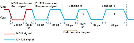
Temperature/Humidity Sensor: DHT22
Measures ambient temperature in Celsius and relative Humidity in Percentage
This specific sensor uses a one-wire data transmission model similar to half-duplex UART. A Pulse Width Modulation (PWM) enabled pin on the Raspberry Pi must be used because of the speed of data transfer
Soil Moisture Sensor: Capacitive Soil Moisture Sensor Module
The sensor returns analog values depending on the soil moisture. Assuming linearity, this is translated into percentage of moisture in the garden from dry to very wet.
This capacitive sensor doesn't have exposed electrodes. It doesn't directly measure the amount of moisture in the soil, it instead measures changes in capacitance or the changes the dielectric medium in the middle of the capacitive sensor. Instead of directly measuring the moisture, it measures the ions dissolved in the moisture. Concentration of ions are affected by several different factor like adding fertilizer which will decrease the resistance of the soil.
Warning Light: G4 LED Bulb 1.5W AC/DC 12V Bi-Pin Base Light
Digital control signals are On/Off
Since the Raspberry Pi utilizes 3.3V logic levels for all inputs and outputs, the sensor is activated using a MOSFET Switching circuit to provide the 12V signal required to energize the light. A flyback diode is NOT required for this because it is a resistive load.
Warning Speaker: EK2148 3V Active Buzzer
Digital control signals are On/Off
Generates a frequency to activate a piezoelectric buzzer that produces a loud continuous tone. To produce a louder sound, a larger input voltage can be placed on the device that is within operating range its specifications.


3.1.2.2 Raspberry Pi
The main control point of the Physical Components is a Raspberry Pi. All the sensors will feed data to the Pi, and the Pi in turn sends that data to the server.
Raspberry Pi Model: PI 4 B
3.1.2.3 Sensors and Raspberry Pi Connectivity
All Sensors in the physical sensor suite will be transmitting data to the Raspberry Pi. The Raspberry Pi in turn will take readings of the sensors in given time intervals. Some of the sensors will require an Analog Input on the board like the water flow meter. To accomplish this, an additional ADC IC Chip like the ADS1115 will be used by connecting it to the I2C bus on the board. The I2C bus can also be used to expand the digital IO of the board.
3.1.2.4 Raspberry Pi and Server Connectivity
The raspberry pi is required to be connected to the internet. When required, the Raspberry Pi will submit HTTP Requests to the Server. For the Reverse Connection, the Raspberry Pi will be required to be connected via a Static IP address and Reserved Port.
3.1.2.5 Hardware Schematic
Below is the final electrical schematic that was designed using the electrical feature in Fusion 360

3.1.2.6 Supporting Passive Components
Several passive components are required to allow proper functionality of the devices.
- MOSFET Switching Circuit: Pulldown Resistor A high value resistor of at least 10kΩ is required at the gate of the RFP30N06LE N-Channel MOSFET to prevent a floating voltage when the gate is not activated. The resistor is high enough value that when the control signal at the gate is set to logic level high, it is able to activate the MOSFET.
- MOSFET Switching Circuit: Current Limiting Resistor It is required to place a resistor at the gate in series with the control signal coming from the Raspberry Pi to protect it from reverse current. Because of the properties of a MOSFET, it acts as a capacitor and has the possibility holding charge until the gate is activated, sinking all the accumulated charge to the gate. Since the Raspberry Pi uses 3.3V logic levels and supports up to 16mA current draw at the GPIO, Ohm's Law can be used to calculate the resistor value required. That can be seen below:
- Power Electronics: Logic Level Switcher Since the Raspberry Pi uses 3.3V logic levels and the MOSFET gate requires 5V for optimal operation, it is possible to use another transistor to make this possible. More specifically, the Bi-Directional SparkFun Logic Level Converter uses several BSS138 transistors to achieve this. In order to avoid this, a transistor with RDSon of minimum 2.5V is required but are several times more expensive and harder to find.
- Power Electronics: Buck Convertors There are several components that work at different voltages. The Solenoid and Light require 12V, the Raspberry Pi requires 5V input power and the Logic Level Shifter also requires 5V at one of the rails. For this reason, there are 2 voltage convertors that step down the voltage from 12V. This enables the system to have only one central power supply of 12V/2A.
- DHT22: Pull-up Resistor To ensure the output signal from the DHT22 is being read correctly by the Raspberry Pi, a pull-up resistor. This makes it easier to determine a logic level change at the input of the Raspberry Pi.
3.1.3.1 Raspberry Pi
The Raspberry Pi 4B is running the latest bullseye release of Raspberry Pi OS Lite. This is a headless version of Embedded Debian Linux, allowing processing power to be used by the SMRT GRDYN program instead of sharing it with graphical user interface and unnecessary bloatware.
Below are the list of required packages:
| Required Packages | Version |
|---|---|
| Adafruit-Blinka | 6.15.0 |
| Adafruit-GPIO | 1.0.3 |
| Adafruit-PlatformDetect | 3.17.2 |
| Adafruit-PureIO | 1.1.9 |
| adafruit-circuitpython-ads1x15 | 2.2.10 |
| adafruit-circuitpython-busdevice | 5.1.1 |
| adafruit-circuitpython-dht | 3.7.0 |
| pip | 21.1.2 |
| pyftdi | 0.53.3 |
| pyserial | 3.5 |
| pyusb | 1.2.1 |
| setuptools | 57.0.0 |
| six | 1.15.0 |
| wheel | 0.36.2 |
3.1.3.2 Server
The server is set up as a RESTful API. This means that it can accommodate: PUT, POST, GET, and DELETE functions.
Below is the official API Documentation for the Smrt Grdyn Server


3.1.3.3 Server and Raspberry Pi Connectivity
All communications from the Pi will be sent over HTTP Post Requests. The endpoints that the Raspberry Pi will send information to include:
- api/v1/garden_registration/pi
- api/v1/garden_data_collection/save
- api/v1/notifications (POST)
- api/v1/garden_images (POST)
End point 1 is used during garden registration. Sending a post request to this endpoint "Opens" a garden registration request, and
needs the User's username, and a 6 element registration code labeled "piId"End point 2 is used for saving the recorded garden data, this includes such things as the recorded temperature, humidity, soil moisture, water flow,
whether the water is on or off, and the time and date of the recording. The Registered Garden ID is also sent with this information to denote which garden the information came from.The other 2 end points are used during notification generation. Data send to the endpoint 3 include the notification type, message, garden id, and time it was generated. If the notification was "animal", typically, the Raspberry Pi would send the corresponding image to end point 4, including with it the garden Id, and time submitted with the notification.
3.1.3.4 Client and Server Connectivity
The Client Software, i.e. Front-End, UI, connects to the Server via POST and GET requests outlined below:
- api/v1/user_session/login
- api/v1/user_session/logout
- api/v1/user_registration
- api/v1/user_session/get_gardens
- api/v1/user_session/default_garden
- api/v1/user_session/setDefault
- api/v1/user_session/get_gardens
- api/v1/garden_data_collection/latest
- api/v1/garden_data_collection/range
- api/v1/garden_registration/user
- api/v1/notifications (GET)
- api/v1/garden_images (GET)
- api/v1/connection (GET)
Reference the above API documentation to understand what each of these do.
3.2.1 FR1: User Registration
The user shall be able to register an account using the website. When the user arrives at the landing page of the website, they shall be greeted with a “Login/Register” form. The user will be able to select “Register” and be presented with the appropriate form. To register an account, the user will submit a Unique Username and A password containing at least 8 characters. The password will contain at least 1 uppercase, 1 lowercase, and 1 special character. If the Username meets the requirements of being unique, and the password contains the above, then their account will be registered, and they will be logged in.
3.2.2 FR2: User Login
Once a User has registered an account, they will be able to log in with the same Username and Password they have registered their account with. There is currently no way to change the user’s password, future versions may contain this feature. Once logged in, they will be directed to the dashboard page. Invalid information will result in an Error message displaying, informing the user that the information they entered is incorrect.
3.2.3 FR3: Store User Account Information
When a User successfully registers their account, or when they add a garden to their account, the server will save this information in persistent storage.
3.2.4 FR4: Garden Registration
A user will be able to Register a Garden (Physical Sensor Suite) with their account. To do so, the User will enter their Username at the Raspberry Pi installed at their physical garden. The Raspberry Pi will then generate a “Registration Id”. Then the Pi will send a Registration request to the server containing both the Username and “Registration Id”. Upon successful transmission, the User will be presented with the “Registration Id” created by the PI. The user will then save this ID. The user will then log in, and find the “Add Garden” page where they will be presented with an input box that asks for the Registration ID. The user will enter the Registration ID, and click submit. The server will receive this information and complete the Logical registration. The user is then prompted to enter a User Friendly name for their new garden. The User will enter their desired name, and this completes the Total registration process.
3.2.5 FR5: Store Garden Information
The Garden Information refers to the Unique Garden ID, Host Name, Port Number, Registered User, and Garden Name that are associated with a Physical Sensor Suite (Garden). This information will be able to be persistently stored by the Server.
3.2.6 FR6: Measure Garden Health
In this context, Garden Health refers to the values measured by the Physical Sensor Suite. These values include: Soil Moisture, Humidity Surrounding the Garden, Ambient Temperature of the Air, Amount of Water flowing to the Soil, and a Status Indicator that is used to tell if the Water is On or Off. The physical sensor suite will be responsible for measuring all of these values.
3.2.7 FR7: Store Garden Health Information
All values measured from FR6 will be able to be persistently stored through the server for later access.
3.2.8 FR8: Viewable Garden Health Information
The User will be able to login and see the most recent data measured from the Physical Sensor Suite of their selected garden. They will also be able to view a range of past data presented in the form of a graph. The user will also be able to specify a specific range of data they would like to view, this will also be presented in a graph. Future plans include viewing a specific data point determined by the timestamp.
3.2.9 FR9: Image Capture Upon Animal Detection
The Camera sensor included with the Physical Components shall be able to capture an image when an animal is detected inside the garden boundary. It must not take a blank or black capture, but be an image that clearly depicts the contents.
3.2.10 FR10: Store Garden Images
All images captured by the Camera Sensor will be able to be persistently stored on the server for later use.
3.2.11 FR11: Viewable Stored Images
The captured images from FR10 will be able to be retrieved from the server and displayed for the user upon request. These photos will be accompanied by the “notification” they originated from.
3.2.12 FR12: Animal Detection
The Animal detection system will be able to visually detect when an animal has crossed the garden threshold. Upon detection, the system should capture and save an image to the server. Then a notification will be sent to the user. Future plans of this feature include the ability for the user to manually turn animal detection off when they enter their own garden.
3.2.13 FR13: Automatic Watering
The Automatic Watering Detection system will be able to tell when the garden needs to be watered by using a capacitive soil moisture sensor to retrieve the current moisture level of the soil in the garden. A solenoid valve will be used to open and close a way for water to travel through the water lines. To add some safeguards to the system, the water flow meters will be used in series with the solenoid valves.
3.2.14 FR14: User Controlled Watering
When the User does not want the Water to be controlled by the system, they will have the option to turn it off. This will be done through the user’s account on the website. Under Settings, the user will be able to set the Automatic Watering Status to On or Off. Future plans include the user being able to deactivate Automatic watering for a set amount of time if they wish.
3.2.15 FR15: Garden to Server Communication
The installed Sensor suite will be able to routinely send information to the server without any interference from the user. The Sensor suite, or more specifically the Raspberry Pi, will have to have internet access to achieve this.
3.2.16 FR16: Server To Garden Communication
For the user to send signals to the Sensor suite, e.g. “Turning Water Off”, the server will have to retrieve relevant connection information to the Raspberry Pi. This includes things like the Host Name, and Port Number that the Pi listens for.
3.2.17 FR17: Notification upon animal detection
When an animal is detected, A notification will be generated. This notification includes the Day and Time of the Detection and the Image data. The notification will be presented to the user when they next login.
3.2.18 FR18: Notification upon possible water leak
When a water leak is detected, a notification will be generated and stored. This notification will include the Day and Time the leak was detected, and Why the notification was generated. This notification will be presented to the user upon their next login.
3.2.19 FR19: Detect Water Leak
If the flow meters are detecting the flow of water in the lines but the solenoid valve is registering as off or closed, then something must be wrong in the system. This could mean a break in the waterline, a bad solenoid, or a reverse in polarity for the valves. If this is the case, a notification should be sent out to the user admin(s) requesting them to fix the issue as soon as possible.
3.2.20 FR20: Warning System
The Warning System will be used in conjunction with Animal Detection and Leak Detection. If anything wrong is detected from the garden from the previous systems mentioned, a light and loud speaker will be activated, cycling through specific patterns depending on the warning.

Author – Ryan Anderson
Purpose - This diagram illustrates all the functionality directly available to the user. It does not contain any information about how the rest of the system works.
Priority - This is the general use case of the system from a user perspective. It retains the highest priority for completion upon deployment.
Preconditions - The user will have to have an internet connection, and have the sensor suite installed properly, before all functions in this use case are available. For data within a time range, a set time, e.g. 5 minutes, must have elapsed since the garden has been registered.
Post conditions - The user will have a valid working account, and their installed sensor suite will be registered to their account. There will be at least 1 entry of data from the garden(sensor suite) to the server.
Actors – Human, Client
Flow of Events
Basic Flow - The user will register an account, and login. Then the user will register a garden(sensor suite) with their account. Once this is complete, then the user can either view their garden data, or make a control request.Exceptions - If the garden(sensor suite) is not properly installed, the user will not be able to view their gardens data, or make control requests.

Author – Jose Maciel Torres
Purpose - This diagram illustrates all the functionality for the lower level systems, (hardware interfacing), once a control command from the server reaches the Raspberry Pi or periodic posts are made to the server.
Priority - Retains highest priority to allow proper functionality and proper data gathering.
Preconditions - All peripherals must be properly working with no damages. Garden registration must be completed successfully prior to expected operation.
Post conditions - Correct data will be gathered and sent to the server for user display. Sensors will be activated or deactivated depending of executed command from the server or sensor values.
Actors – Client, Server
Flow of Events
Basic Flow - Once a command is received, the Raspberry Pi interfaces with the peripherals according to the feature operations. Watering will activate the solenoid, data gathering will access the data of most sensors, and animal detection will interface with the warning devices.

Author – Noah Anderson
Purpose - This diagram illustrates how all the entities, or tables, in the database are related to eachother.
Priority - This is core to the development of the server. The functionality of the system as a whole depends on maintaining the format, it retains high priority.
Preconditions - These Tables are generated at start up, or updated after that. These tables need no be filled before launch of the server.
Post conditions - These tables and entities will remain filled and stored in the database
Garden Image Sequence Diagram

Garden Registration Sequence Diagram

Garden Sensor Sequence Diagram

Notification Sequence Diagram

User Session Sequence Diagram

User Control Sequence Diagram

User Registration Sequence Diagram

The database uses 7 SQL tables to store data collected from the various hardware sensors as well as user data. These tables are titled as follows: user_information, connection_information, sensor_data, garden_images, registration_request, garden_name, and notification_information. These are illustrated below.
user_information
username hashed_password default garden gardenUser1 1234 1 GreenFinger123 1111 2 This table contains the Unique username, hashed password, and default garden of the user. When the user registers an account, they submit must submit a Unique username, and a plain-text password. Those two values are then passed to the server, and it is then the servers job to generate a salt and hashed password using this information. A 'salt' is a user-specific generated string that gets attached to the password, before the password is hashed. Once the server has generated the salt and hashed password, the username, and hashed password are then saved to this table. When the user logs in the default garden (if one exists) will be automatically selected.
connection_information
username garden_id host port gardenUser1 1 127.3.14.4 69 gardenUser1 3 10.1.1.197 44 GreenFinger123 2 168.12.1.22 80 For the server to connect to the raspberry pi, it needs its ip address and the port number it receives information through. The fields host and port, respectively, store these values. Host is a String or VarChar type that will contain the host name, ie the public ip address, of the raspberry pi. Port is a numerical value Int, that will store the port number the the raspberry pi listens for.
The garden_id field will store a UUID, which is a 128-bit Universally Unique Identifier that is generated by the server upon garden registration. The username field will contain a String or VarChar value that represents the unique username the user registered their account with.
sensor_data
garden_id timestamp water_flow humidity soil_moisture temperature water_active 1 010520211500 0 34 15 95 false 1 010520211530 10 35 16 92 true 3 010520211530 0 30 13 92 false 2 010520211500 10 37 14 94 false The sensor_data table is the cornerstone of the database. This table stores all the data that is read from the physical sensor suite. The primary key for this table is the garden_id, which stated above is a UUID type. However, due to the feature to search a time range for data, a composite key consisting of the primary key and timestamp will be used to identify entries. The timestamp will be a SQL TIMESTAMP value, which will denote the time the readings were taken. The water_flow field will store a DOUBLE that denotes the amount of water that is used per unit of time e.g. liters per second. The ph_balance will store an INT that denotes the acidity of the soil, using the standard pH scale. The soil moisture field will be a DOUBLE type that will reflect how wet or dry the soil is. The temperature field will also be a DOUBLE type that denotes the local ambient temperature of the garden in Celsius. Lastly the water_active field will be a BOOLEAN type that denotes whether the water is on or off at the time of the reading.
garden_images
garden_id timestamp image_path 1 010520211500 1/img1.jpg 1 010520211530 1/img2.jpg 3 010520211630 3/img1.jpg This table uses the same data type for the garden_id and timestamp that the sensor_data table uses. The image_path field will be a VARCHAR type that denotes the relative file path to an image captured by the animal detection system. This table uses the garden_id as the primary key, and the timestamp for creating a composite key. This table also retains a foreign key relation through the garden_id field.
registration_request
registration_id username garden_id sd80sm90m greenfinger 1 00sks91 johnSmith 4 This table is designed for user when a user wished to register a garden with their account. The unique registration_id created by the registration request is saved in the registration_id field, and will be a VARCHAR type. The username and garden_id fields are the same type as in the tables above. This table uses a foreign key relation through the garden_id field. Data in this table will be dropped after a set period of time, around 5 minutes.
This schema uses foreign key relations that are based on some combination of username and garden_id. Because of this, users are restricted to registering with unique usernames. When a table contains the field 'garden_id', that field shall contain a UUID or Universally Unique Identifier. This identifier is a 128-bit unique identifier that is generated by the server. These foreign key relations allow users to have multiple gardens registered to them, and to allow multiple users to be connected to a single garden.
garden_name
garden_id username garden_name 1 JonDoe Jon's Garden 3 SarahW Sarah's Flowers This table is used when a user registers their garden for the first time. Since UUID's are not human friendly, this system allows users to name a newly registered garden into something memorable. Entries in this table are tracked by the garden_id field, and verified by the username field.
notification_information
garden_id timestamp notification_type 2 20150328233327 animal 1 20210913030334 water_leak The notification_information table contains information for a notification, including which garden it is for, the time the notification triggered, and the type of notification. The garden_id is a foreign key referencing the connection information table. The timestamp is another component of the primary key of each row, and functions the same as the timestamp in the sensor_data table. The notification_type is an enumerated string that describes the type of notification, which is either animal or water_leak, both of which are triggered by the sensor suite. The garden_id and notification_type will be stored as a VARCHAR and the timestamp will be stored as a timestamp data type.
The main performance goals concern the response time when communicating between subsystems. Firstly, there is the communication stemming from the user interacting with the web page. The response time for any user request should not exceed 1 minute. These user requests include requests to display data, to take a data snapshot, to modify user attributes, and to add a new garden. In order to achieve this each connection between subsystems will need to meet performance goals. The response time for the server contacting the sensor suite through the raspberry pi should not exceed 30 seconds. Any query or push to the database from the server should not take longer than 10 seconds. Secondly, the entire system should not be unavailable for extended periods. Specifically, any portion of the online system should not be inaccessible for longer than 1 consecutive hour, and total downtime should not exceed 20 hours in any calendar month.
The main focus of safety and security requirements are with password confidentiality and data integrity. Password data will be secured through a hashing and salting process. Concretely, salts will be added to a password and then it will be passed through the Bcrypt algorithm before being stored in the database. Passwords will not be stored in any other form throughout the system, meaning that plain text passwords can not be exposed through other data security flaws. Passwords will be further protected by constraints on the users passwords. Specifically, passwords must contain at least 8 characters, with at least one uppercase letter, one lower case letter, one symbol, and one number. This makes potential user passwords sufficiently complicated enough to deter brute force attacks.
The system will ensure data integrity through database constraints, as well as other protective measures. First, the garden registration process will ensure that both the physical owner of the raspberry pi, as well as the registered user the garden is being registered to, are aware of the registration. The pi will be confirmed by requiring an install package to be downloaded and run as well as the user’s username to be entered into the pi. The user will be required to log into the web page to confirm the registration request initiated by the pi. Together these two constraints ensure that only the pi owner and account owner can register a given garden to a given user. This shows data integrity since it means that invalid garden-user pairings can not be added to the database. Secondly, once a garden has been registered, the garden’s unique id will be stored among other information in the connection_information table. All other data about the garden stored in other tables, such as sensor readings in the sensor_data table, will have a garden_id column which is a foreign key referencing the garden_id column of the connection_information table. This constraint ensures that any other garden-related data added to the database must reference an existing garden. This further ensures data integrity by disallowing extraneous data from being added to the database. Furthermore, this ensures that garden-related data in the database must be retrievable. This is true because the garden_id being referenced must be associated with a real user’s username in the connection_information table since the username comes from the registration process which involves the user logging in to the system. This means that gardens must be associated with an already registered user, meaning that when that user logs in, the system will be able to use their username to look up garden(s) associated with them, and then access any other garden data using the garden_id. Lastly, data uploaded from the raspberry pi will always be accompanied by the unique id generated during the registration process. This ensures that only the pi that went through the registration process can upload data to the database, further ensuring data integrity.
The system will be adaptable in order to be able to function correctly regardless of location, plant choice, or other garden-specific factors. One way this is achieved is though the hardware specifications. The sensors and watering system are flexible to be able to apply to a range of garden sizes. Specifically, the system should function for gardens sized 100 to 300 square feet . Another aspect of adaptability lies in the ability for one user to control multiple garden systems. This allows for further adaptability since one user can have multiple systems and each could be responsible for small gardens or parts of a larger garden. Specifically, the system should support one user having an arbitrary number of gardens registered to them, and each individual garden should maintain the same level of functionality as if the user only had one garden.
Interoperability will be important for this system, since several different subsystems will need to communicate with each other in a secure, predictable manner. The subsystems involved will be the webpage, server back end, database, and the sensor suite. Interoperability will be achieved in different ways for each connection between subsystems. The connection from the server to the database will do this through data constraints. The database will receive information locally through the server back-end. The database will ensure normalcy through constraints which will ensure that the server can not push invalid or inaccessible data. The server back-end will access data in the database locally through SQL queries. The webpage will take in input from the user and go through the server back-end locally to request information from either the database or send information to the sensor hardware. Explicitly, the user will obtain or send information first by going through the web page, which will then send requests to the appropriate subsystem through the server back-end. Lastly the sensor hardware will communicate with the raspberry pi locally, which will then send HTTP requests to the server back-end. The raspberry pi will receive information from the server back-end through a Java WebSocket.