hn / ginlong-solis Goto Github PK
View Code? Open in Web Editor NEWSolis inverter ESP8266 data logger, S3 WiFi stick reverse engineering and ESPhome firmware
Solis inverter ESP8266 data logger, S3 WiFi stick reverse engineering and ESPhome firmware


Thanks for the comprehensive code and documentation on this.
I have a S5-GR3P15K 3 phase Solis inverter and after following your excellent guide and building a ESP8266 logger I have Solis inverter type definition = 0x0000 outputted to the serial console. Does this mean that my inverter isn't being seen or that it's not currently supported?
If someone could point me in the right direction on how to start debugging this I would love to be able to try and get my inverter supported.
Trying to backup the stock firmware fails for me, to the best of my knowledge I have followed the instructions so need to ask for help...
I am quite sure I am able to "Set the MCU to UART boot mode (#9)" since the stick does not start flashing all it's LEDs, only power LED is lit (if the stick boots regularly all the LEDs light up) if I try and read the stick with
sudo screen /dev/ttyUSB0 115200
I only get a continuous "spamming line" of "????????????" so I guess the baud rate might be wrong in this mode, I have tried 9600 also but that gives nothing.
Once in the mode where only the power LED is lit I try to run
./rtltool.py -p /dev/ttyUSB0 rf 0x8000000 0x800000 solis-s3-firmware-1012f.bin
But I get the following error
./rtltool.py -p /dev/ttyUSB0 rf 0x8000000 0x800000 solis-s3-firmware-1012f.bin File "/home/test/Desktop/solis/./rtltool.py", line 56 print 'Error: Open %s, %d baud!' % (port, baud) ^^^^^^^^^^^^^^^^^^^^^^^^^^^^^^^^^^^^^^^^^^^^^^^ SyntaxError: Missing parentheses in call to 'print'. Did you mean print(...)?
I am using the rtltool linked in the guide ( https://github.com/pvvx/RTL0B_SDK/blob/master/mkb/rtltool.py )
Any idea what I could be doing wrong? I have also tried with the stick not connected and the same error appears so I guess there is something wrong with my rtltool.py or the arguments I am trying to pass.
Sorry for the very basic question, but even though I'm familiar with ESPHome and Home Assistant, I've never actually flashed the firmware on any other device!
My understanding is that I need to connect the S3 wifi stick via a serial adapter to my Raspberry Pi and then I can run the commands in the readme. Will the following adapter work?
https://www.amazon.co.uk/dp/B08CRL6KHV?psc=1&ref=ppx_yo2ov_dt_b_product_details
Do I then attach wires between the stick and the serial adapter (TX to TX, RX to RX and GND to GND)?

I understand that I will need to connect the TX pin to GND at boot so the firmware can be flashed.
I then think I just type the code into a terminal on the Pi and the stick will be updated with ESPHome firmware that will provide data directly to Home Assistant?
Thanks in advance for any help, I don't want to fry the wifi stick by doing this wrong!
180 102 0 22 x xx xxxx
110  F2 2 21 x xx xxxx
110  F2 2 19 x xx xxxx
180 504 0 xx x xx xxxx
Regarding serial numbers, it seems the digits for models have been extended by one digit, 102 is shown as version in the Soliscloud for a S6-GR1P1.5K-M-DC where as F2 is shown for a RHI-4.6K-48ES-5G-EU as well as RHI-4.6K-48ES (4G !, maybe distinguished by product date cut-off?). 504 is a S5-GR3P8K,
Just as a test I tried to compile the firmware with the latest version (when writing this - v1.2.0) of LibreTiny and got the following error
python3 -m esphome compile solis-esphome-emw3080.yaml
INFO ESPHome 2023.8.0-dev
INFO Reading configuration solis-esphome-emw3080.yaml...
Failed config

libretiny: [source solis-esphome-emw3080.yaml:44]

  The LibreTiny component is now split between supported chip families.
  Migrate your config file to include a chip-based configuration, instead of the 'libretiny:' block.
  For example 'bk72xx:' or 'rtl87xx:'.
  board: generic-rtl8710bx-4mb-980k
  framework:
    version: latest
I guess some modifications are needed to make this project compatible with latest LibreTiny.
Hello @hn,
I'm trying to flash esphome image to the Solis S3 WiFi Data Logging Stick (3rd gen). I followed your instructions, but the very last step fails with just a generic error:
user@linux-pc:~/rtltool/libretiny-esphome$ python3 -m esphome upload solis-inv-esphome.yaml --device /dev/ttyUSB0
INFO Reading configuration solis-inv-esphome.yaml...
Processing solis-inv (board: generic-rtl8710bx-4mb-980k; framework: arduino; platform: libretiny)

Configuring upload protocol...
AVAILABLE: uart
CURRENT: upload_protocol = uart
Looking for upload port...
Using manually specified: /dev/ttyUSB0
Uploading .pioenvs/solis-inv/firmware.uf2
|-- Detected file type: UF2 - esphome 2023.5.0-dev
|-- Connecting to 'Realtek AmebaZ' on /dev/ttyUSB0 @ 1500000
|   |-- Success! Chip info: Realtek RTL87xxB
|-- Writing '.pioenvs/solis-inv/firmware.uf2'
|   |-- esphome 2023.5.0-dev @ 2023-04-29 22:50:42 -> generic-rtl8710bx-4mb-980k
|-- ValueError: Failed to write to 0x800B000
|   |-- File "/home/user/.local/lib/python3.10/site-packages/ltchiptool/soc/ambz/flash.py", line 147, in flash_write_raw
*** [upload] Error 1
The stick is in bricked state after flashing fails. I managed to restore the stock firmware by running (MCU is in UART boot mode):
user@linux-pc:~/rtltool$ python3 rtltool.py -p /dev/ttyUSB0 wf 0x8000000 solis-s3-firmware-1012f.bin
Connecting...
Write Flash data 0x08000000 to 0x08800000 from file: solis-s3-firmware-1012f.bin ...
Traceback (most recent call last):
  File "/home/user/rtltool/rtltool.py", line 523, in <module>
    main(*sys.argv[1:])
  File "/home/user/rtltool/rtltool.py", line 388, in main
    for _ in gen:
TypeError: 'bool' object is not iterable
Even though I get this error, the stick seems to work fine with the stock firmware.
Any ideas what I might be doing wrong?
Hi again, long time no see :)
So I read that there was a new way to flash the stick via ESPHome, figured why not.... and this is probably where I made a mistake.
I read up on all instructions and ignored the manual flashing part, since my stick was already running custom firmware and was reachable via IP I figured I could just flash the stick via OTA directly instead of doing it manually via serial first.
I put together a configuration, re-checked everything and figured it was all good, validated the config and hit install via wireless, all looked good but when a few minutes passed I figured something was wrong.... I took the stick inside to see what it was doing and it's just boot looping with the following output
ROM:[V0.1]
FLASHRATE:4
BOOT TYPE:0 XTAL:40000000
IMG1 DATA[1128:10002000]
IMG1 ENTRY[800053d:100021ef]
IMG1 ENTER
CHIPID[000000ff]
read_mode idx:2, flash_speed idx:2
calibration_result:[1:19:13][3:15]
calibration_result:[2:21:11][1:15]
calibration_result:[3:0:0][ff:ff]
calibration_ok:[2:21:11]
FLASH CALIB[NEW OK]
OTA2 ADDR[8100000]
OTAx SELE[f8000000]
OTA2 USE
OTA2 SIGN[35393138:31313738]
IMG2 DATA[0x81a80c0:4496:0x10005000]
IMG2 SIGN[RTKWin(10005008)]
IMG2 ENTRY[0x10005000:0x81361ad]
BOOT_FLASH_RDP RDP enable
RDP bin decryption Failed!
checksum_ipsec = 0x4e784fc0, checksum_rdp_flash = 0xfd90f7a6
System_Init1
System_Init2
I [      0.000] LibreTiny v1.5.0 on generic-rtl8710bx-4mb-980k, compiled at Feb 22 2024 18:08:06, GCC 10.3.1 (-Os)
[I][logger:403]: Log initialized
[C][ota:483]: There have been 1 suspected unsuccessful boot attempts.
[D][lt.preferences:104]: Saving 1 preferences to flash...
[D][lt.preferences:132]: Saving 1 preferences to flash: 0 cached, 1 written, 0 failed
[I][app:029]: Running through setup()...
[C][uart.lt:049]: Setting up UART...
[C][switch.gpio:011]: Setting up GPIO Switch 'led_orange_com'...
[D][switch:016]: 'led_orange_com' Turning OFF.
[D][switch:055]: 'led_orange_com': Sending state OFF
[D][switch:016]: 'led_orange_com' Turning OFF.
[C][switch.gpio:011]: Setting up GPIO Switch 'led_green_net'...
[D][switch:016]: 'led_green_net' Turning OFF.
[D][switch:055]: 'led_green_net': Sending state OFF
[D][switch:016]: 'led_green_net' Turning OFF.
[C][switch.gpio:011]: Setting up GPIO Switch 'wdt_reset'...
[D][switch:016]: 'wdt_reset' Turning OFF.
[D][switch:055]: 'wdt_reset': Sending state OFF
[D][switch:016]: 'wdt_reset' Turning OFF.
[D][binary_sensor:034]: 'button_reset': Sending initial state OFF
[C][wifi:038]: Setting up WiFi...
[C][wifi:051]: Starting WiFi...
[C][wifi:052]:   Local MAC: 80:A0:36:A7:F7:1F
interface 0 is initialized
                          interface 1 is initialized

Initializing WIFI ...
WIFI initialized
                [D][wifi:459]: Starting scan...
RTL8195A[HAL]: Hard Fault Error!!!!
RTL8195A[HAL]: R0 = 0x1b9
RTL8195A[HAL]: R1 = 0x1
RTL8195A[HAL]: R2 = 0x0
RTL8195A[HAL]: R3 = 0x9
RTL8195A[HAL]: R12 = 0x1b9
RTL8195A[HAL]: LR = 0x8110bad
RTL8195A[HAL]: PC = 0x1eb8dcf0
RTL8195A[HAL]: PSR = 0x80000000
RTL8195A[HAL]: BFAR = 0xe000ed38
RTL8195A[HAL]: CFSR = 0x20000
RTL8195A[HAL]: HFSR = 0x40000000
RTL8195A[HAL]: DFSR = 0x0
RTL8195A[HAL]: AFSR = 0x0
RTL8195A[HAL]: PriMask 0x0
RTL8195A[HAL]: BasePri 0x0
RTL8195A[HAL]: SVC priority: 0x00
RTL8195A[HAL]: PendSVC priority: 0xf0
RTL8195A[HAL]: Systick priority: 0xf0
And that just repeats over and over again
If I try to pull TX pin 21 low during boot to re-flash the stick via serial it just won't work
python2 rtltool2.py -p /dev/ttyUSB0 gf
Connecting...
Flash Status value: 0x15

python2 rtltool2.py -p /dev/ttyUSB0 wf 0xb000 solis-emw3080-0x00B000.bin
Connecting...
Write Flash data 0x0800b000 to 0x080b424c from file: solis-emw3080-0x00B000.bin ...
Error: Write Flash!
I see that the flash status is 0x15 and not 0x40 as in the guide, quite sure I did not see this before when we did all the troubleshooting back in last year before I started to use a better serial adapter and I am using the same good adapter now so that should not be the issue.
Any ideas what could be wrong? Did I finally manage to kill the stick with my curiosity....
Hello
in receive next error when i compile , someone ?,
Someone who can help ?
/data/cache/platformio/packages/toolchain-gccarmnoneeabi/bin/../lib/gcc/arm-none-eabi/10.3.1/../../../../arm-none-eabi/bin/ld: .pioenvs/solis-emw3080/raw_firmware.ota1.elf section .ram_heap.data' will not fit in region BD_RAM'
/data/cache/platformio/packages/toolchain-gccarmnoneeabi/bin/../lib/gcc/arm-none-eabi/10.3.1/../../../../arm-none-eabi/bin/ld: region `BD_RAM' overflowed by 224 bytes
collect2: error: ld returned 1 exit status
|-- Generated file not found: .pioenvs/solis-emw3080/raw_firmware.ota1.elf
*** [.pioenvs/solis-emw3080/raw_firmware.elf] Error 1
To be able to determine the inverter type automatically, the exact content of ModBus register 35000 is important. There seem to be different interpretations of the documentation, so it would be interesting to collect as many register values as possible here to create a robust detection logic.
If you want to contribute, just post here:
Inverter type as printed on the unit:
Type definition (reg 35000):
Model type (reg 3000 for INV, reg 33000 for ESINV):
Please pay attention to whether the value is hexadecimal or decimal, this seems to be an inconsistency.
Is it possible to view/set the battery SOC from Home Assistant? From the sccreenshots it appears to only be voltage and current.
Is it possible to view the kWh that has been sent/received to/from the battery?
Do you think it would be possible to reduce the data synchronisation interval? At the moment the data is updated every minute. I'd like to go down to 2 seconds for certain sensors. Do you have any ideas?
Thanks
This is maybe more of a question than an issue I guess but creating one anyway to make sure.
This morning I flashed the latest possible build with ESPHome and LibreTiny 1.5.1, all works perfect so far for 10 minutes.
Since I now have the stick compiled and monitored via Home Assistant I saw the log output after compile and OTA update and I then noticed this between the readouts of data from the inverter.
[07:57:27][W][component:214]: Component modbus_controller took a long time for an operation (0.12 s).
[07:57:27][W][component:215]: Components should block for at most 20-30ms.

[07:58:25][W][component:214]: Component modbus_controller took a long time for an operation (0.06 s).
[07:58:25][W][component:215]: Components should block for at most 20-30ms.

[07:58:25][W][component:214]: Component modbus_controller took a long time for an operation (0.08 s).
[07:58:25][W][component:215]: Components should block for at most 20-30ms.

[07:58:25][W][component:214]: Component modbus_controller took a long time for an operation (0.12 s).
[07:58:25][W][component:215]: Components should block for at most 20-30ms.
If this is expected warnings just ignore and close this ticket but maybe there is something to tweak to avoid these warnings in the logs?
Hi,
I have only spent about 1,5 days running this project on my Solis stick now but one of my findings so far is that about every 15 minutes or so the readings in Home Assistant for a split second becomes Unavailable and then goes back just as fast, I have tried to get a recording of this to show for demonstration purposes but no luck yet with that.
This seems to happen on most if not all the values I read out but the value I know it happens for and that causes issues for me is Active Power, the reason I know this is that I spent hours trying to figure out why one of my automation's stopped working when I changed from my Pi running https://github.com/incub77/solis2mqtt to reading stuff out with the Solis stick, the automation is simple, if Active Power is above 750W for 20 minutes it should turn on a power outlet, I noticed this had not happened for many hours of Active Power being greater than 750W, when I was looking at this I noticed with my eyes how Active Power all of a sudden was Unavailable and then back to whatever the actual power was, since this seems to happen around every ~15 minutes or so my automation of 20 minutes won't trigger since the value has not been above 750 for 20 minutes with these small Unavailable breaks in between, I could just lower the timer on my automation and be done with it but I figured it's best to report it if it might be something that could be solved.
I am 99% sure this is not related to my reportings regarding WiFi here #12 since I see the stick online via ping at the same time as values becomes Unavailable.
The only "proof" I can show of this issue now is based on the "Logbook" in Home Assistant, however for some reason the Active Power does not get logged there so I will show history of the value for Country Code instead

Also here it can be seen as small gaps in the timeline

Now this is for Country Code as and example, even more values does this at the same time

And then they return within the same second or 1-2 seconds after.
Any ideas what could be causing this?
I can just lower the timers on my automation but hopefully we can figure out the issue and resolve it.
Sometimes ModBus traffic fails with CRC errors after several hours of correct operation:
[W][modbus:109]: Modbus CRC Check failed! 8498!=10
[W][modbus:109]: Modbus CRC Check failed! 4F02!=10
[W][modbus:109]: Modbus CRC Check failed! 83D2!=10
Once these errors have started, the system is desynchronised and only a reboot will fix the problem.
This topic has been discussed in various places and I would like to collect all the information here.
I've heard of older wifi data logger modules being capable of updating settings on their solis inverter remotely (via Home assistant automation for example). Does this integration provide that capability?
Hi, I build the configuration for the esp version with an ESP32. I get al the data but it is not possible to limit the output power from my solis S6-GR1P4K converter.
In HA is a message: this entity is switch off. Is there a way to enable this function?

Dear Hajo,
your code is genius. Thanks for this. Surely beyond my own skills..
Planning to fork your code and add MQTT - at least MQTT is running already in mine testbed successful
I realized my Solis Inverter (solis-rhi-3k-48es-5g) does not get detected, hence the script did not work as expected:
Register 35000 delivers: 2031--- 1 phase LV AC Couple energy storage inverter
Made those changes to accomodate:
case SDT_ITYPE:  /* Solis inverter type definition, switches lookup table */
    {
      char buf[2 + 4 + 1];
      unsigned int regvalue = modbus.getResponseBuffer(0);

      sprintf(buf, "0x%04X", regvalue);
      Serial.print(buf);


      if ((regvalue / 100) == 10) {           /* RS485_MODBUS (INV-3000ID EPM-36000ID) inverter protocol */
        solis = solisINV;
      } else if ((regvalue / 100) == 20) {    /* RS485_MODBUS (ESINV-33000ID) energy storage inverter protocol */
        solis = solisESINV;
      } else if ((regvalue) == 8241) {    /* RS485_MODBUS solis-rhi-3k-48es-5g */
        solis = solisESINV;

      }
    }
    break;
Reading of Serial somehow fails as well. Still looking into this and will you keep updated.
Again, thanks for this execellent piece of work
thanks
I have an error when uploading the firmware. It start flashing, then after some time, I am getting an error : ValueError: Failed to write to 0x800B000
Here is the log :
➜  libretiny-esphome git:(platform/libretuya) ✗ python3.10 -m esphome upload solis2-stick.yaml --device
/dev/tty.SLAB_USBtoUART
INFO Reading configuration solis2-stick.yaml...
****************************************************************************************************************************************************************************************************************************************************************************************************************************************************************************
Obsolete PIO Core v6.1.6 is used (previous was 6.1.7)
Please remove multiple PIO Cores from a system:
https://docs.platformio.org/en/latest/core/installation/troubleshooting.html
****************************************************************************************************************************************************************************************************************************************************************************************************************************************************************************
Processing solis2-stick (board: generic-rtl8710bx-4mb-980k; framework: arduino; platform: libretiny)
----------------------------------------------------------------------------------------------------------------------------------------------------------------------------------------------------------------------------------------------------------------------------------------------------------------------------------------------------------------------------
Configuring upload protocol...
AVAILABLE: uart
CURRENT: upload_protocol = uart
Looking for upload port...
Using manually specified: /dev/tty.SLAB_USBtoUART
Uploading .pioenvs/solis2-stick/firmware.uf2
|-- Detected file type: UF2 - esphome 2023.5.0-dev
|-- Connecting to 'Realtek AmebaZ' on /dev/tty.SLAB_USBtoUART @ 1500000
|   |-- Success! Chip info: Realtek RTL87xxB
|-- Writing '.pioenvs/solis2-stick/firmware.uf2'
|   |-- esphome 2023.5.0-dev @ 2023-05-23 00:27:42 -> generic-rtl8710bx-4mb-980k
|-- ValueError: Failed to write to 0x800B000
|   |-- File "/usr/local/lib/python3.10/site-packages/ltchiptool/soc/ambz/flash.py", line 147, in flash_write_raw
My chip looks the same as yours :

First of I found this issue libretiny-eu/libretiny#113 but that seems to be resolved or at least closed so not sure if this is a new issue or the same.
Regarding versions and so on running on the stick I just got my stick to work last night (07 July 2023) so everything is the latest there is to my knowledge following the guide here https://github.com/hn/ginlong-solis#replacing-the-main-application
The stick worked perfect last night for a few hours when I was testing things out, this morning when I woke up everything was still working, the stick goes offline during the night on my inverter but that is expected since the inverter powers down the COM-port, I know this from running this project https://github.com/incub77/solis2mqtt before getting my stick re-flashed, I had to use external power on the Pi to keep it running during the night.
This morning I tested more things, when I powered down a access point I have in the house all of a sudden I lost the Solis stick, I waited a few minutes expecting it to reconnect back but it did not, I powered on the access point again and waited but the stick did not reconnect. I have now power cycled the stick 4 times, waited 10-20 minutes in between but it has not reconnected.
I don't have easy serial access to the stick right now since I assembled the case again but I guess that is the next step to see what is going on unless someone have some other tips for me.
The only thing that worries me is this line I noticed during boot of the Solis stick
[W][ota:102]: Last Boot was an unhandled reset, will proceed to safe mode in 7 restarts
I saw this number go down every time I booted the stick with serial connected so.... maybe the stick is stuck in safe mode now?
..... Now all of a sudden it just works again.....
So.... during the time I was writing this ticket (20 minutes maybe since last stick power cycle) the stick just all of a sudden connected back after 2927 seconds (had a rolling ping towards it that is how I know the number of second, it was rebooted several times during these 2927 seconds so why it decided to work now I have no clue...)
I will post this ticket anyway now in case there is some discussion to have regarding this, if this is excepted behavior I guess we can just close this ticket.
Hi
Not an issue with the project or the code but asking here anyway in case someone else wonders and can look up this ticket.
"Set the MCU to UART boot mode (pull TX pin low during boot)"
I am not familiar what it means to pull a pin low, I am using a USB to serial adapter and can read the boot process just fine with a speed of 115200, however to enter into "Set the MCU to UART boot mode" I need to pull the TX pin low, could someone explain how that is done?
Maybe it can't be performed with a regular cheap USB to Serial adapter?
Hi all,
I'm quite used to flashing devices using UART (mostly shelly plugs and sonoff switches) but this wifi stick is giving me more problems that I anticipated :-/
I had the same as user Belaial (from the image here) and I can confirm what kuba2k2 mentioned here: these adapters are apparently not strong enough for the required baudrate. I bought a new one, based on the FT232 and only with that adapter was able to communicate in the download mode, using ltchiptool-v4.10.2.
I compiled the firmware using esphome on my other computer, and tried to flash the firmware.uf2 using the Windows version. However, during upload, I get the following errors:
I: Found new device: COM7 - USB Serial Port - FTDI (0403/6001)
I: Transmission successful (ACK received).
I: Transmission successful (ACK received).
E: send error: expected ACK; got b'\x15' for block 2
E: send error: expected ACK; got b'\x15' for block 2
E: send error: expected ACK; got b'\x15' for block 19
E: send error: expected ACK; got b'\x15' for block 19
E: send error: expected ACK; got b'\x15' for block 23
E: send error: expected ACK; got b'\x15' for block 23
...
E: send error: expected ACK; got b'\x15' for block 168
E: send error: expected ACK; got b'\x15' for block 168
I: Transmission successful (ACK received).
I: Transmission successful (ACK received).
I: Transmission successful (ACK received).
I: Transmission successful (ACK received).
I'm not quite sure what these write errors have as a consequence, but I've tried it multiple times and I think the amount of errors differs between some runs. When I read out the terminal during normal boot, it always reboots during the scanning of the wifi:
<RTL8195A>ROM:[V0.1]
FLASHRATE:4
BOOT TYPE:0 XTAL:40000000
IMG1 DATA[1128:10002000]
IMG1 ENTRY[800053d:100021ef]
IMG1 ENTER
CHIPID[000000ff]
read_mode idx:0, flash_speed idx:0
calibration_result:[1:0:0][ff:ff]
calibration_result:[2:0:0][ff:ff]
calibration_result:[3:0:0][ff:ff]

FLASH Calibration Fail!!!
Please set proper flash speed and read mode in SYSTEM DATA!!!

OTA2 ADDR[8100000]
OTAx SELE[ffffffff]
OTA1 USE
IMG2 DATA[0x80b40d0:4520:0x10005000]
IMG2 SIGN[RTKWin(10005008)]
IMG2 ENTRY[0x10005000:0x8041eb1]
BOOT_FLASH_RDP RDP enable
SYSTEM.bin RDP Empty.
System_Init1
System_Init2
I [      0.000] LibreTiny v1.5.0 on generic-rtl8710bx-4mb-980k, compiled at Feb 29 2024 05:55:03, GCC 10.3.1 (-Os)
[I][logger:395]: Log initialized
[C][ota:473]: There have been 9 suspected unsuccessful boot attempts.
[D][lt.preferences:104]: Saving 1 preferences to flash...
[D][lt.preferences:132]: Saving 1 preferences to flash: 0 cached, 1 written, 0 failed
[I][app:029]: Running through setup()...
[C][uart.lt:049]: Setting up UART...
[C][switch.gpio:011]: Setting up GPIO Switch 'led_orange_com'...
[D][switch:016]: 'led_orange_com' Turning OFF.
[D][switch:055]: 'led_orange_com': Sending state OFF
[D][switch:016]: 'led_orange_com' Turning OFF.
[C][switch.gpio:011]: Setting up GPIO Switch 'led_green_net'...
[D][switch:016]: 'led_green_net' Turning OFF.
[D][switch:055]: 'led_green_net': Sending state OFF
[D][switch:016]: 'led_green_net' Turning OFF.
[C][switch.gpio:011]: Setting up GPIO Switch 'wdt_reset'...
[D][switch:016]: 'wdt_reset' Turning OFF.
[D][switch:055]: 'wdt_reset': Sending state OFF
[D][switch:016]: 'wdt_reset' Turning OFF.
[D][binary_sensor:034]: 'button_reset': Sending initial state OFF
[C][wifi:038]: Setting up WiFi...
[C][wifi:051]: Starting WiFi...
[C][wifi:052]:   Local MAC: D0:BA:E4:88:8E:EC
interface 0 is initialized
interface 1 is initialized

Initializing WIFI ...
WIFI initialized
[D][wifi:455]: Starting scan...
<RTL8195A>ROM:[V0.1]
FLASHRATE:4
BOOT TYPE:0 XTAL:40000000
IMG1 DATA[1128:10002000]
IMG1 ENTRY[800053d:100021ef]
IMG1 ENTER
CHIPID[000000ff]
read_mode idx:0, flash_speed idx:0
calibration_result:[1:0:0][ff:ff]
calibration_result:[2:0:0][ff:ff]
calibration_result:[3:0:0][ff:ff]

FLASH Calibration Fail!!!
Please set proper flash speed and read mode in SYSTEM DATA!!!

OTA2 ADDR[8100000]
OTAx SELE[ffffffff]
OTA1 USE
IMG2 DATA[0x80b40d0:4520:0x10005000]
IMG2 SIGN[RTKWin(10005008)]
IMG2 ENTRY[0x10005000:0x8041eb1]
BOOT_FLASH_RDP RDP enable
SYSTEM.bin RDP Empty.
System_Init1
System_Init2
I [      0.000] LibreTiny v1.5.0 on generic-rtl8710bx-4mb-980k, compiled at Feb 29 2024 05:55:03, GCC 10.3.1 (-Os)
[I][logger:395]: Log initialized
[C][ota:473]: There have been 10 suspected unsuccessful boot attempts.
[D][lt.preferences:104]: Saving 1 preferences to flash...
[D][lt.preferences:132]: Saving 1 preferences to flash: 0 cached, 1 written, 0 failed
[E][ota:480]: Boot loop detected. Proceeding to safe mode.
[I][app:029]: Running through setup()...
[C][wifi:038]: Setting up WiFi...
[C][wifi:051]: Starting WiFi...
[C][wifi:052]:   Local MAC: D0:BA:E4:88:8E:EC
interface 0 is initialized
interface 1 is initialized

Initializing WIFI ...
WIFI initialized
[D][wifi:455]: Starting scan...
<RTL8195A>ROM:[V0.1]
FLASHRATE:4
BOOT TYPE:0 XTAL:40000000
I think there is a problem during data transfer, but I've already tried 2 different set of cables, including the one that came with the adapter. Can anyone recommend cables? Or is there an other issue at play?
Thanks in advance,
Erwin
I try the Wemos D1 mini - variant and got the following output:
... [08:40:47][E][modbus_controller:095]: Modbus error - last command: function code=0x4 register address = 0x8161 registers count=1 payload size=0 ...
Ideas?
I'm (currently) not using many sensors that the inverter provides, but I noticed there is a difference between what I used to get from SolisCloud versus what ESPHome now reports.
SolisCloud / ESPHome


Notably, I appear to be missing the Solis AC Output Total Power which depicts my solar production, and Solis Battery Power which shows me power flowing to/from the battery.
Unless that's what Total DC output power is supposed to report? It's reporting 0W while I would expect to still be drawing power from my battery as it's still 45% full.
Active Power perhaps? Or does that include solar?
Also, somehow the Solis integration was reporting 2493kWh of Total Energy produced, while ESPHome now "only" reports 2486kWh?
I did, shortly, have a different Solis inverter before it got replaced with my current, so maybe the first only produced 7kWh and the SolisCloud integration is reporting the sum of the 2 although it created 2 devices for the 2 inverters?
Hi, last night I switched out my Raspberry Pi running https://github.com/incub77/solis2mqtt for the modified Solis stick, I waited until after midnight since I did not want to mess up my graphs in HA.
This morning I woke up hoping to see everything work (Inverter had the COM-port down when I plugged in the stick so it did not boot up until later when I was asleep) to my surprise tho the stick was offline when I woke up, I went out to check on it and it had power but no connection, I pressed the reset button on the back of the stick and it then booted up and connected just fine.
I later did some quick tests with this complied and flashed (used 3 minutes to put it under the interval: 280s in commit b25f978,
wifi:
  reboot_timeout: 3min
But it seems the stick does not reboot when WiFi is not connected, could this somehow be related to the commit b25f978 which fixed the hardware watchdog we had issues with before?
I was asked to check this before (see below), I did however not test what would happen in WiFi was not connected, only that it stopped the reboot every 15 minutes due to the hardware watchdog.
@Belaial Can you please check b25f978 . It sends a 100ms 'high' pulse every just under 5 minutes to reset the WDT, but only if WiFi is connected (so it should catch WiFi reconnect problems as well).
I only have one Solis S3 stick and it's now connected to the inverter so don't want to remove it since it's collecting data (can remove it after midnight if needed for more testing), do you happen to have more than one stick @hn ? Was thinking if you could do a quick test to see if b25f978 interferes with the reboot if WiFi is not connected.
I don't see how b25f978 could interfere with the reboot if not connected to WiFi but need to ask since I'm out of ideas..
EDIT
(On vacation so might reply very slow in case some testing is needed)
Hi,
I have an Solis RHI-5K-48ES-5G, and I'm using a wifi stick flashed with the latest firmware (as discussed here), and I'm having these strange values for "Active Power":
 .
.
I can try to templatize this to remove these peaks, but was wondering if anyone else has seen this as well?
Thanks,
Erwin
Hi
I'm attempting to flash my S3-WIFI-ST stick but I can´t even get serial comms to works.
I hooked up the module to my FTDI adapter.
Set the adapter to 3.3V, tried 5V as well*. (this says 3V, this says 5V?)
VCC -> 3.3V/5V
TX -> RX
RX -> TX
GND -> GND
(Jumper between TX and GND)
dmesg output
[ 5325.135580] usb 1-4: USB disconnect, device number 10
[ 5364.899209] usb 1-4: new full-speed USB device number 11 using xhci_hcd
[ 5365.321499] usb 1-4: New USB device found, idVendor=0403, idProduct=6001, bcdDevice= 6.00
[ 5365.321506] usb 1-4: New USB device strings: Mfr=1, Product=2, SerialNumber=3
[ 5365.321508] usb 1-4: Product: FT232R USB UART
[ 5365.321510] usb 1-4: Manufacturer: FTDI
[ 5365.321512] usb 1-4: SerialNumber: A50285BI
[ 5365.350420] BPF: 	 type_id=138692 bits_offset=0
[ 5365.350425] BPF:
[ 5365.350426] BPF: Invalid name
[ 5365.350428] BPF:
[ 5365.350429] failed to validate module [usbserial] BTF: -22
Of course ltchuptool can´t identify the correct serial port.
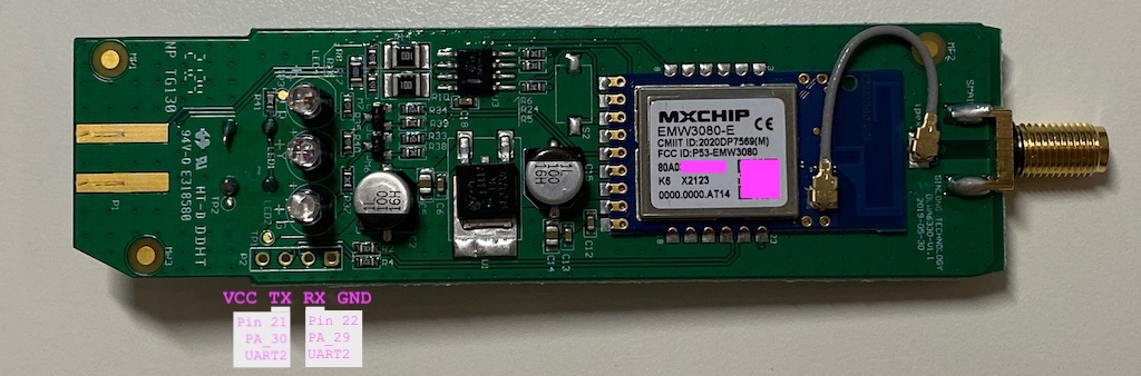
Stick has a MXCHIP EMW3080-E. Firmware version 00010186
I'm working on Pop!_OS (Linux 6.8.0-76060800daily20240311-generic #202403110203~1711393930~22.04~331756a SMP PREEMPT_DYNAMIC Mon M x86_64 x86_64 x86_64 GNU/Linux)
Hi,
I was going to build the latest firmware to include the fix for modbus getting desynchronised, however I must be doing something wrong.
I started of fresh from the beginning, all works until this line
wget https://raw.githubusercontent.com/hn/ginlong-solis/libretiny-ringbuffer-workaround.diff
That throws a 400: Invalid request, was fixed with using this link instead for me (notice the /master/ part in the working link)
https://raw.githubusercontent.com/hn/ginlong-solis/master/libretiny-ringbuffer-workaround.diff
However later on in the guide when I am about to apply the fix contained in libretiny-ringbuffer-workaround.diff I get the following
~/.platformio$ patch -p1 < libretiny-ringbuffer-workaround.diff
can't find file to patch at input line 6
Perhaps you used the wrong -p or --strip option?
The text leading up to this was:
--------------------------
|Workaround for the Arduino ringbuffer, so that it can no longer have a permanently
|inconsistent state. Implemented by removing the redunant storage of the buffer
|state in three variables.
|--- a/packages/framework-arduino-api/api/RingBuffer.h	2023-08-12 13:07:59.074806708 +0200
|+++ b/packages/framework-arduino-api/api/RingBuffer.h	2023-08-11 15:35:11.847630525 +0200
--------------------------
File to patch:
I tried looking for the file

I also tried to manually find the file but I don't even have the framework-arduino-api folder
~/.platformio/packages$ ll
total 44
drwxrwxr-x 11 user user 4096 Aug 15 09:32  ./
drwxrwxr-x  5 user user 4096 Aug 15 09:36  ../
drwx------  7 user user 4096 Aug 15 09:31  library-flashdb/
drwx------  4 user user 4096 Jul  7 22:14  library-freertos/
drwx------  7 user user 4096 Aug 15 09:31  library-freertos-port/
drwx------  7 user user 4096 Jul  7 22:14  library-lwip/
drwx------  6 user user 4096 Aug 15 09:31  library-printf/
drwx------  6 user user 4096 Aug 15 09:31  library-uf2ota/
drwx------  8 user user 4096 Aug 15 09:32  toolchain-gccarmnoneeabi/
drwx------ 10 user user 4096 Jul 17 12:00 '[email protected]'/
drwx------  3 user user 4096 Jul  7 22:14  tool-scons/
Am I missing something here? Sorry in advance if I am doing something obviously wrong...
Hello,
I successfully dumped the original firmware from the Datalogger Model S3 and have been experimented with various codes using PlatformIO. Uploading codes to the chip has been smooth without any issues.
But, I encountered an error when attempting to flash the firmware file generated using ESPHome as the instructions. As I'm new to ESPHome,

I hope this data is enough for troubleshooting.
Thank you!
Hi,
First of all: thank you for making this possible, and for all the work that you have put in this! I don't like the need of pulling my data from the ginlong servers, and this projects would fit all my needs.
I've set up a wemos D1 device using ESPHome as indicated in the readme, device_base solis-modbus-esinv.yaml. The RX/TX lights of the RS485-to-serial adapter are blinking. However, I can't get this to work: the state of all sensors is "NA" and I'm getting the following from the logs:
[D][modbus_controller:040]: Modbus command to device=1 register=0x8119 countdown=0 no response received - removed from send queue [D][modbus_controller:040]: Modbus command to device=1 register=0x8121 countdown=0 no response received - removed from send queue [D][modbus_controller:040]: Modbus command to device=1 register=0x8131 countdown=0 no response received - removed from send queue [D][modbus_controller:040]: Modbus command to device=1 register=0x8137 countdown=0 no response received - removed from send queue [D][modbus_controller:040]: Modbus command to device=1 register=0x8161 countdown=0 no response received - removed from send queue
I'll be very honest to start off: this whole modbus thing is super new to me and I'm still quite confused about this. Any hints as to what is happening or where to start troubleshooting, would be very much appreciated :)
Thank you in advance!
Kind regards,
Erwin
A declarative, efficient, and flexible JavaScript library for building user interfaces.
🖖 Vue.js is a progressive, incrementally-adoptable JavaScript framework for building UI on the web.
TypeScript is a superset of JavaScript that compiles to clean JavaScript output.
An Open Source Machine Learning Framework for Everyone
The Web framework for perfectionists with deadlines.
A PHP framework for web artisans
Bring data to life with SVG, Canvas and HTML. 📊📈🎉
JavaScript (JS) is a lightweight interpreted programming language with first-class functions.
Some thing interesting about web. New door for the world.
A server is a program made to process requests and deliver data to clients.
Machine learning is a way of modeling and interpreting data that allows a piece of software to respond intelligently.
Some thing interesting about visualization, use data art
Some thing interesting about game, make everyone happy.
We are working to build community through open source technology. NB: members must have two-factor auth.
Open source projects and samples from Microsoft.
Google ❤️ Open Source for everyone.
Alibaba Open Source for everyone
Data-Driven Documents codes.
China tencent open source team.