Giter VIP home page Giter VIP logo

tle493d-3dmagnetic-sensor's Introduction

3D-Magnetic-Sensor-2GO

Build Status

Library of Infineon's 3D magnetic sensor TLE493D family (currently supporting W2B6, A2B6 and P2B6) for Arduino. Notice that it is enough to use the class Tle493d if you want to use the basic setup. Classes Tle493d-w2b6, Tle493d-a2b6 and Tle493d-p2b6 offers additional device-specific features.

Summary

The 3D Magnetic Sensor 2GO is a budget-priced evaluation board equipped with the magnetic sensor TLE493D for three dimensional measurement combined with an ARM® Cortex™-M0 CPU. The 3D Magnetic Sensor 2GO has a complete set of on-board devices, including an on-board debugger. Build your own application and gadget with the 3D Magnetic Sensor 2GO.

Usage

Please follow the example sketches in the /examples directory in this library to learn more about the usage of the library.

Currently you have to make sure which sensor type you are using. The default type is A0:

Tle493d(AccessMode_e mode = MASTERCONTROLLEDMODE, TypeAddress_e productType = TLE493D_A0);

Known Issues

  • Reset sequence not working for TLE493d-W2B6. (Requires further testing)
mInterface.bus->begin();
mInterface.bus->write(0xFF);
mInterface.bus->end();

mInterface.bus->begin();
mInterface.bus->write(0xFF);
mInterface.bus->end();

mInterface.bus->begin();
mInterface.bus->write(0x00);
mInterface.bus->end();

mInterface.bus->begin();
mInterface.bus->write(0x00);
mInterface.bus->end();
  • TLE493D-A2B6 does not work with low power mode.

  • Sensor does not respond after being reconnected. As mentioned in this issue, the sensor works after being flashed, but not after being powered off and powered on again. This is temporarily solved by twice writing out the configuration registers, in order to avoid unexpected INT pulse.

Key Features and Benefits

  • TLE493D-A2B6 and TLE493D-W2B6 (three dimensional magnetic sensor)
  • XMC1100 (ARM® Cortex™-M0 based)
  • On-board J-Link Lite Debugger (Realized with XMC4200 Microcontroller)
  • Power over USB (Micro USB), ESD and reverse current protection

Installation

Integration of XMC in Arduino IDE

Please note that base of the Sensors 2GO is the XMC 2Go from Infineon. Therefore, please install (if not already done) also the XMC-for-Arduino implementation and choose afterwards XMC2Go from the Tools>Board menu in the Arduino IDE if working with this evaluation board.

Integration of Library

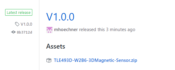
Please download this repository from GitHub by clicking on the following field in the releases of this repository or directly here:

Download Library

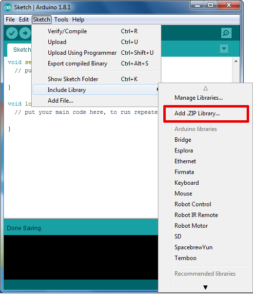
To install the 3D magnetic sensor 2GO library in the Arduino IDE, please go now to Sketch > Include Library > Add .ZIP Library... in the Arduino IDE and navigate to the downloaded .ZIP file of this repository. The library will be installed in your Arduino sketch folder in libraries and you can select as well as include this one to your project under Sketch > Include Library > MagneticSensor3D.

Install Library

Processing

This library supports the open-source software Processing for creating GUIs. It allows you to connect your evaluation board to a PC over serial communication and visualisation of the embedded system. Find out more on the Arduino homepage here. The respective files are stored in the /processing folder of this repository.

3D Printed Add-Ons

The TLx493D eval kit can be combined with several 3D printed mechanical add-ons. Designed to fit the 2Go form factor for quick and easy evaluation of common magnetic mechanical applications. Find out all the available 3D Printed add-ons here.

3D printing files and GUI

Download here the 3D printing files for the mechanical add-ons. You can also find a GUI there for a first evaluation of those add-ons.

Mini Controller with Python

The Mini Control 2Go 3D printer add-ons extends the TLE493D functionalities with several python scripts support. Check out the code in the following repository.

Board Information, Datasheet and Additional Information

A PDF summarizing the features and layout of the 3D magnetic sensor 2GO board is stored on the Infineon homepage here. The datasheet for the TLE493D-W2B6 can be found here TLE493D-W2B6 Datasheet while respective application notes are located here Application Notes.

tle493d-3dmagnetic-sensor's People

Contributors

9volts9er avatar ederjc avatar ivankravets avatar jaenrig-ifx avatar mhoechner avatar sherylll avatar sigizaruba avatar

Stargazers

 avatar  avatar  avatar  avatar  avatar  avatar  avatar  avatar  avatar  avatar  avatar  avatar  avatar  avatar  avatar  avatar  avatar  avatar  avatar  avatar  avatar  avatar  avatar  avatar  avatar  avatar

Watchers

 avatar  avatar  avatar  avatar  avatar  avatar  avatar  avatar  avatar  avatar

tle493d-3dmagnetic-sensor's Issues

MS2GO keeps giving a wrong XYZ-values (-266.24) from serial monitor

I have noticed there are some similar cloased issues yet no detailed solution has been provided. Like it happened to #25 , the poster seems don't know the answer either with the bug just disappear itself. But for me, -266.24 just keeps appear in my serial monitor.

image

I am using a tle493d w2b6 MS2GO, arduino (2.1.1), TLE493D library(1.3.0) and XMC 2.2.0

I presume it may relate to J-link or board itself, because there's only one time it goes well with right XYZ-output when i reinstall the J-link, update it from an old version. But it soon broke after i reupload the code. I aslo tried FASTMODE and every possible operations from other cloased issues but it is just still broken.

I'm totally noob on this stuff, hoping someone can give me some advice. Thank you very much!

THANKS!

TLE493D getting stuck (maybe defective)

Hi,

I have some problems with a TLE493D / this library acting very strange. I'm not sure if the sensor is defective or it's a software problem.

Not sure which variant of the TLE493D it is, but here is a closeup:
https://hackster.imgix.net/uploads/attachments/500027/20180610_094241_8VdXg5Id29.jpg?auto=compress%2Cformat&w=1280&h=960&fit=max

So, sometimes the TLE493D / library works fine, but sometimes the sensor just gets stuck and nothing helps. Neither a complete power off on both the sensor and the micro-controller.

When the sensor is stuck the symptoms are one of the following:

  • .updateData() returns Tle493d_Error::TLE493D_BUS_ERROR
  • .updateData() returns with Tle493d_Error::TLE493D_NO_ERROR, but .getX(), .getY(), .getZ() all returns ZERO-s

When it works fine .updateData() return TLE493D_NO_ERROR and I have correct sensor values.

Currently, I'm using the TLE493D connected directly to a nRF51, but I had this problem Sensor2Go board too.

I would need some help investigating this issue.

Thanks,
Attila

Improving sampling rate in Arduino IDE with multiple sensors

Hey there!
Currently i am using 4 different sensors and it is going well so far, but i was asking myself if it is possible to improve the sampling rate..
I think right now it is around 50Hz and it is not as fast as i want it to be. On the datasheet it also says that a rate of 7,8 kHz is possible. Not sure under which circumstances this is achievable but i get the feeling that there is room for improvement with the current rate i have. Or maybe this is just the limit with a serial communication with arduino..
Any kind of help is much appreciated as always!
Thank you very much

Screenshot (167)

Bus error

Hi,

I have looked on this forum and on the Arduino forum, but for the life of me I can't figure out what's wrong...

I'm using a bare metal TLE493D-W2B6 A3 and have wired everything up on my breadboard with an Arduino Uno. I'm using 3V3 and have added 1K pull-up resistors as well.

I have uploaded the cartesian.ino example just to test everything but I always get the same values for all 3 axis (-266.24) even when I get a magnet real close. I have checked the value returned by the updateData function and I get 1. Which means I have a bus error. However I don't really know what to do with this...

I have used the i2c scanner to check the device's address and it returns 0x44 alright.

It looks like it's working for a couple of seconds at a time (the value returned becomes 1 and the values are closer to 0), I don't know why, I'm not doing anything... This is really puzzling to me.

I'm using the Arduino IDE 2.0.3 on MacOS.

All help is welcome!

TLE493D code setting address to the default A0 after compiling

Hey there!

I've already been trying to solve this myself by scrolling through the other issues but unfortunately I can't find a solution.

I have a self designed PCB with 4 of the TLE493D-W2B6 sensors, one of each type (A0,A1,A2,A3) so that I have 4 different addresses available. When using an i2c adress scanner I detect all of the four different addresses. But if I scan again after using the following code (which only leads to an output of sensor1 (A0)) I only scan one address with that one being the default address 0x35. I can't find what is causing this problem. I'm working with an arduino uno.

Edit: This also happens if I only use one sensor different than A0 and the cartesian sketch provided. To me it looks like the library somehow changes the address to the default address every time.

Has anyone an idea what could cause that problem?

Thanks in advance!
Best Simon

#include <Tle493d.h>
#include <Tle493d_w2b6.h>


// Four sensors with different I2C addresses
Tle493d_w2b6 Sensor1 = Tle493d_w2b6(Tle493d::FASTMODE, Tle493d::TLE493D_A0);
Tle493d_w2b6 Sensor2 = Tle493d_w2b6(Tle493d::FASTMODE, Tle493d::TLE493D_A1);
Tle493d_w2b6 Sensor3 = Tle493d_w2b6(Tle493d::FASTMODE, Tle493d::TLE493D_A2);
Tle493d_w2b6 Sensor4 = Tle493d_w2b6(Tle493d::FASTMODE, Tle493d::TLE493D_A3);


void setup() {
  Serial.begin(9600);
  while (!Serial);

  // Initialize all sensors
  Sensor1.begin();
  Sensor2.begin();
  Sensor3.begin();
  Sensor4.begin();
}

void loop() {
  // Reading data from all sensors
  Sensor1.updateData();
  Sensor2.updateData();
  Sensor3.updateData();
  Sensor4.updateData();

  // Printing data to console
  Serial.print("Sensor 1\t");
  Serial.print(Sensor1.getX());
  Serial.print(" , ");
  Serial.print(Sensor1.getY());
  Serial.print(" , ");
  Serial.println(Sensor1.getZ());  
  Serial.print("Sensor 2\t");
  Serial.print(Sensor2.getX());
  Serial.print(" , ");
  Serial.print(Sensor2.getY());
  Serial.print(" , ");
  Serial.println(Sensor2.getZ());
  Serial.print("Sensor 3\t");
  Serial.print(Sensor3.getX());
  Serial.print(" , ");
  Serial.print(Sensor3.getY());
  Serial.print(" , ");
  Serial.println(Sensor3.getZ());
  Serial.print("Sensor 4\t");
  Serial.print(Sensor4.getX());
  Serial.print(" , ");
  Serial.print(Sensor4.getY());
  Serial.print(" , ");
  Serial.println(Sensor4.getZ());
  Serial.println();
  
  delay(500);
}

four_different_addresses multi_sensor_not_working only_default_address

-266.24

Hey. Can you help? in Cartesian.ino example error after uncommenting lines

//If using the MS2Go-Kit: Enable following lines to switch on the sensor
pinMode(LED2, OUTPUT);
digitalWrite(LED2, HIGH);
delay(50);

code does not working

Error:
pinMode(LED2, OUTPUT);
^~~~
FE2

exit status 1

Compilation error: 'LED2' was not declared in this scope

What should I do?

TLE493D-A2B6 cannot run properly in arduino DUE and Teensy boards.

Hi, I have some problem that the example codes didn't work properly in arduino due or Tennsy boards.
The function getX(), getY(), getZ() just return -0.13 or -266.24 all the time, and the return variable updateData() got 1 (TLE493D_BUS_ERROR).

The sensor I chose is TLE493D-A2B6.
I have seen some previous related issues, issues , but it seem that this problem still appear in some application?
Is this problem had been solved?
Or just the boards incompatible ?

How to set short range mode?

Hi.
How could I configure the short range mode with this library?
I'm using the TLE493D W2B6 A0 sensor and I need to increase the sensitivity by setting the short range mode.

Bug: TLE93_p2b6_A1 not working

Hi there,

I tried to make a TLE493DP2B6A1 working with an Adafruit Feather. I used the actual Master branch and not the old release, because of the PR #20.

My Code looks like this:

`
#include <Arduino.h>
#include <Tle493d.h>
#include <Tle493d_p2b6.h>
Tle493d_p2b6 Tle493dMagnetic3DSensor = Tle493d_p2b6(Tle493d::MASTERCONTROLLEDMODE, Tle493d::TLE493D_A1);

void setup() {
Serial.begin(9600);
while (!Serial);
Tle493dMagnetic3DSensor.begin();
Tle493dMagnetic3DSensor.enableTemp();
}

void loop() {
Tle493dMagnetic3DSensor.updateData();

Serial.print(Tle493dMagnetic3DSensor.getX());
Serial.print(" ; ");
Serial.print(Tle493dMagnetic3DSensor.getY());
Serial.print(" ; ");
Serial.println(Tle493dMagnetic3DSensor.getZ());
delay(500);
}
`

I have also thief the Fast Mode, but the results is always:
-266.24 ; -266.24 ; -266.24

Has anyone an idea how to make the sensor work?

Thanks in advance!

best,
Norbert

resetSensor() works after calling begin()

I noticed in the comments that resetSensor() freezes the microcontroller. I was experiencing issues with startup and the reset section (2.3) in the TLE493D-W2B6 User Manual seemed to explain what was happening. If I ran resetSensor() at startup, it would freeze, but I found out that this code always works:

void setup() {
  // Need to start, reset, then start again to deal with power up glitches
  Tle493dMagnetic3DSensor.begin();
  Tle493dMagnetic3DSensor.resetSensor();
  Tle493dMagnetic3DSensor.begin();
  //... continue on with normal code

I didn't dig into it to see what part of begin() fixes the issue but there seems to be a fix to this bug somewhere in there. Good luck finding it.

PWM output

Actually I am searching how could set PWM out according to x,y,z direction movement of magnet. I use platform io with XMC 2Go Kit (actually my board contain TLE493D on board. TLE493D-p2b6-2go) after some test I understand that some pin of board (You may see the image) 1,2,3 has pwm out option I mean when ı connect led to number 1 pin ı can control its brightness like below code.

for(int k=255; k >= 0; k--){
analogWrite(pin1, k);
delay(5);
}

similar this , I want to map x direction magnetic value for controlling led brightness.
is this possible such a thing.

Best regards.

Getting following isssue

--------------------------
Infineon XMC Flasher Lite
Copyright Infineon Technologies 2017
--------------------------
Windows 10
Operating System: Windows 10

Initialisation
--------------------------
Windows 10

[Error] Infineon.DebuggerExceptions: It seems that JLink software is not installed please download from www.segger.com and install it. You can specify it by setting java property xmcFlasher.JLink.dllPath 

MS2Go doesnt return correct values

Hey!
I just wanted to connect my TLE493D MS2Go shield to my computer and try a few things for the documentation of my project (multiple sensors etc.) and at first everything worked completley fine... but i only deleted and reinstalled the XMC board and since then i dont get correct values on my serial monitor and i dont know why.

I downloaded again the newest version of the library
Screenshot (252)

This is the XMC Board version i downloaded
Screenshot (251)

even after going back to Version 1.5 which i had before, it still doesnt work...

And these are the "settings" lets say that i have in the IDE
Screenshot (255)

And the code used is the one provided in the examples Cartesian.ino

My serial monitor looks like this

Screenshot (253)

The only thing i can think of, is there maybe a special version of the XMC Board that i need to download to run this thing? Really weird.. as always i appreciate every bit of help :) Thank you very much guys!

Edit: I just deleted and reinstalled everything from the Arduino IDE and it still doesnt work... Dont know whats going on

Operating with multiple senors; Type TLE493D-W2B6

Hey there!
As i described in #17 i want to work with 4 of the TLE493d-a2b6 simultaneously. So far i designed my pcb board, installed ONE test sensor and i can see the data on my serial monitor in the Arduino IDE using the updated library.

So now i am trying to change the address of that sensor, because when the other ones are installed, i want to communicate with each of them seperately via I^2C and receive my data.

This turned out to be much more difficult than expected. The code in the library is quite complex (for me at least) and after working on it with multiple people, we still couldn´t figure out how to do it.

So after receiving great help yesterday, i thought maybe somebody else already faced a problem like this and has some advice for me.

I welcome and appreciate every help i can get!

Mega 2560 with -266.24

Sorry to bother here, but -266.24 just keeps appear in my serial monitor, too. (I have looked up other similar closed issues.) My self-design PCB use two 1K2 Ohm pull-up resisters and one 100nF capacitance. Mega 2560 is my miu-C, however I notice that its pins 20(SDA) and 21(SCL) already integrated with pull-up resisters whose exact value or the voltage be pulled-up to I can't find. I try to remove the two 1K2 Ohm, but also didn't work. I wonder what other problems it may be? (My sensor is TLE493D-W2B6-A3-HTSAI)

Tle493d-A3 Bare Chip only Reading 0xff

Bare chip TLE493D-W2B6-A3, arduino uno chip picked up on scanner (0x44)
can only receive 0xff from registers , although reset code works.
when using library crash occurs when writing to mod1 register as writing anything other the 0xE0 causing chip crash, if i try to bypass mod1 register library will receive same 0xff.

4pcs. of TLE493D-W2B6 (A0 ...A3) + XMC2Go

Hallo Herr Hollfelder,
ich bitte um Hilfe bei der Ausgestaltung eines Arduino-Sketches.
Ich habe den XMC1100 im Einsatz mit 4 Stück TLE493D-W2B6, mit jeweils einer anderen I2C Adresse.
Ziel soll es sein, die Daten aller 3 Achsen aller 4 Sensoren hinter einander weg auszugeben (Reihenfolge egal). Die 3D2G GUI funktioniert nur mit dem Typ A0. Da diese wahrscheinlich derart konzipiert ist, sowieso nur die Daten eines Sensors anzuzeigen, wollte ich über die Arduino IDE alle 4 Sensoren ansprechen und abwechselnd die Daten ausgeben.
Zum Einen bin ich noch ein absoluter Laie im Umgang mit dieser Programmierumgebung, zum Anderen nur Hardware- und nicht Softwareentwickler.

Dieser Aussage entnehme ich, dass man die anzusprechende Adresse im Sketch definieren kann.

As you have the A3 variant, you would need to change the I2C address in the source code or supply the correct one with the Tle493d::begin() function.

Leider habe ich ausser in der Datei "keywords.txt" keine Hinweise darauf gefunden, welche Funktionen die Bibliothek unterstützt bzw. wie diese genau zu verwenden sind.

Meine Frage lautet daher:
Um welche Kommandos muss ich den Beispielsketch "CartesianFast.ino" ergänzen, um die Daten aller 4 Sensoren kontinuierlich ausgeben zu können?

Vielen Dank im Voraus.
Karsten Schmidt

I2C communication with sensor does not work

Hello there!

I got a TLE439DA2B6HTSA1 from Mouser (presuming type A2?) currently connected to Bluepill (stm32f103c8; earlier to ESP8266) and I am (like others) experiencing severe I2C communication issues.

When running the I2C scanner I get immediately after reset

Scanning...
I2C device found at address 0x35 !
done

Scanning...
No I2C devices found

.. the consequent scans are not showing anything anymore. Looks like the sensor (or i2c?) always gets stuck.

The address discovered indicates the device is TLE493D_A0 and not A2 (address 0x78) .. or is it some other device type/kind?

Went already through multiple issues (and solutions) here on github but with no success. For example, the code given in [https://github.com//issues/24] yields

-1 -1 -1 4095

when using sensor address 0x35 (dev type A0) and when the address is 0x78 (A2) the printout is

176 10 0 0

When looking at the SDA line with a scope there is data only for the first transaction and then the i2c communication never proceeds. Same situation with bluepill and esp8226 (hence it is probably not mcu related).

I can also see the nINT pulse on the SCL line. But it problably shouln't be disruptive for the clock signal when it works for others, right?

The SCL & SDA lines are pulled up by a 1k2 resistors and there is a 100pF cap in place of C4 as recommended here [https://www.infineon.com/dgdl/Infineon-Infineon-3DMS2GO_TLE493D-A2B6-UM-v01_02-EN-UserManual-v01_02-EN.pdf?fileId=5546d462636cc8fb01641834364e3f56] in Figure 9. But the cap has no effect on the comms..

Initially I used the libs downloaded from platformio (infineon/TLE493D-Magnetic-Sensor @ ^1.3.0), now got the latest libraries from the github repo.

What am I doing wrong? Any ideas?

Many thanks for your insights!

-266.24 just keeps appear in my serial monitor (TLE493D-W2B6A2)

We have made a custom PCB that connects an ESP32 to TLE493D-W2B6 A2. We have made the schematic using the official datasheet. We are getting -256, 0 or -1 as output. we are using the latest GitHub official library, in the constructor we are providing

Tle493d Tle493dMagnetic3DSensor = Tle493d(Tle493d::MASTERCONTROLLEDMODE,Tle493d::TLE493D_A2);

Will attach the schematic as well.

Please help.

/**
* For basic setup just create a Tle493d() object. If you want to use the wake up mode please use Tle493d_w2b6(). Also
* the setUpdateRate() method is slightly different for different variants
*/


#include <Tle493d.h>

Tle493d Tle493dMagnetic3DSensor = Tle493d(Tle493d::MASTERCONTROLLEDMODE,Tle493d::TLE493D_A2);

void setup() {
  Serial.begin(9600);
  while (!Serial);
  Tle493dMagnetic3DSensor.begin();
  Tle493dMagnetic3DSensor.enableTemp();
}

void loop() {
  Tle493dMagnetic3DSensor.updateData();

  Serial.print(Tle493dMagnetic3DSensor.getX());
  Serial.print(" ; ");
  Serial.print(Tle493dMagnetic3DSensor.getY());
  Serial.print(" ; ");
  Serial.println(Tle493dMagnetic3DSensor.getZ());
  
  delay(500);
}

signal-2024-01-10-152712_002

Add License

Could you add a license to the repository? It's unclear if this library is usable in a commercial project, if it's just for example purposes, or if a license exists elsewhere in the Infineon pages. Thanks!

TLE493d-a2b6 -> Arduino

Hi there!
so i bought the "TLE493D magnetic sensor 2go" and followed the steps on this site (https://github.com/Infineon/TLE493D-3DMagnetic-Sensor) to get the data on my serial monitor
After i did that successfully, i designed a pcb board according to the data sheet and installed the sensor itself on it
(TLE493D - A2B6 3d Magnetic Sensor Eval Kit ///// MPN: TLE493D - A2B6 MS2GO).

The board is connected via 4 pins to an Arduino Mega 2560 and the Arduino to my Laptop.

  • 1st. pin SCL (21)
  • 2nd. pin SDA (20)
  • 3rd. pin 3.3V
  • 4th. GND

WhatsApp Image 2021-07-14 at 15 16 24

As you cann see, in the end i want to have 4 of them on my board. BUT first i need to get the data from one of them on my serial monitor in arduino ide.

I tried to use the previous code and library to get the data but that obviously didnt work (so far) and this is the error message:
Untitled

because i am completely new to all this stuff i´m not sure if there is a very simple solution to my problem or if its gonna be a big issue.

I am thankful for every help i can get and i already appreciate all the stuff i found so far regarding this topic!:)

Little Update:
I found here a similar issue and made small changes:
in Tle493d_conf ---> PD3 and PD0 to PD_3 and PD_0
in Tle493d(cpp) the same

now i am left with this:
asdf

error: expected identifier before numeric constant

Error upon compiling example code

.pio\libdeps\ATmega328PB\TLE493D-Magnetic-Sensor\src./util/Tle493d_conf.h:50:16: error: expected identifier before numeric constant
P, FF, CF, T, PD3, PD0, FRM, //diagnosis (Diag)
^
.pio\libdeps\ATmega328PB\TLE493D-Magnetic-Sensor\src./util/Tle493d_conf.h:50:16: error: expected '}' before numeric
constant
.pio\libdeps\ATmega328PB\TLE493D-Magnetic-Sensor\src./util/Tle493d_conf.h:50:16: error: expected unqualified-id before numeric constant
In file included from .pio\libdeps\ATmega328PB\TLE493D-Magnetic-Sensor\src\Tle493d.h:43:0,
from .pio\libdeps\ATmega328PB\TLE493D-Magnetic-Sensor\src\Tle493d_a2b6.h:5,
from .pio\libdeps\ATmega328PB\TLE493D-Magnetic-Sensor\src\Tle493d_a2b6.cpp:1:
.pio\libdeps\ATmega328PB\TLE493D-Magnetic-Sensor\src./util/Tle493d_conf.h:77:7: error: 'RegMask_t' does not name a type
const RegMask_t regMasks[] = {
^~~~~~~~~
.pio\libdeps\ATmega328PB\TLE493D-Magnetic-Sensor\src./util/Tle493d_conf.h:153:1: error: expected declaration before
'}' token
}
^

Reset sequence with Arduino Wire library.

In the function "Tle493d::resetSensor()" in the file "src/Tle493d.cpp" the reset sequence is commented out at the moment.

User 3Dgeo on the arduino.cc forum made a sequence with the Arduino Wire library to put the 0xFF and 0x00 on the I2C bus.

Wire.requestFrom(0xFF, 0);
Wire.beginTransmission(0x00);
Wire.endTransmission();
Wire.beginTransmission(0x00);
Wire.endTransmission();
delayMicroseconds(30);

The 0xFF is with a read bit, and the 0x00 is with the write bit. Using Arduino functions to read and write makes the sequence.

Recommend Projects

  • React photo React

    A declarative, efficient, and flexible JavaScript library for building user interfaces.

  • Vue.js photo Vue.js

    🖖 Vue.js is a progressive, incrementally-adoptable JavaScript framework for building UI on the web.

  • Typescript photo Typescript

    TypeScript is a superset of JavaScript that compiles to clean JavaScript output.

  • TensorFlow photo TensorFlow

    An Open Source Machine Learning Framework for Everyone

  • Django photo Django

    The Web framework for perfectionists with deadlines.

  • D3 photo D3

    Bring data to life with SVG, Canvas and HTML. 📊📈🎉

Recommend Topics

  • javascript

    JavaScript (JS) is a lightweight interpreted programming language with first-class functions.

  • web

    Some thing interesting about web. New door for the world.

  • server

    A server is a program made to process requests and deliver data to clients.

  • Machine learning

    Machine learning is a way of modeling and interpreting data that allows a piece of software to respond intelligently.

  • Game

    Some thing interesting about game, make everyone happy.

Recommend Org

  • Facebook photo Facebook

    We are working to build community through open source technology. NB: members must have two-factor auth.

  • Microsoft photo Microsoft

    Open source projects and samples from Microsoft.

  • Google photo Google

    Google ❤️ Open Source for everyone.

  • D3 photo D3

    Data-Driven Documents codes.