This repo is for getting started using Locobots in ME326 Collaborative Robotics Course at Stanford University taught by Prof. Monroe Kennedy (Course Website - checkout student implementations and their github repos at the bottom of the page)
If you are new to Linux (how to install ubuntu/linux) and ROS, the following are links you should start with once linux is installed:
- Download ROS (ROS 1, noetic is tested in this example): http://wiki.ros.org/ROS/Installation
- Download vim to edit code/bash/etc in terminal:
$ sudo apt-get update
$ sudo apt-get install vim
- Install net-tools for ifconfig to check network:
sudo apt install net-tools
- Install Terminator for ease of terminal use (through preferences the banner can be removed):
sudo apt-get install terminator
- Install python3
$ sudo apt-get update
$ sudo apt-get install python3.6
- Install scipy
sudo apt-get install python3-scipy
- Install python-catkin-tools:
$ sudo sh \
    -c 'echo "deb http://packages.ros.org/ros/ubuntu `lsb_release -sc` main" \
 > /etc/apt/sources.list.d/ros-latest.list'
$ wget http://packages.ros.org/ros.key -O - | sudo apt-key add -
then
$ sudo apt-get update
$ sudo apt-get install python3-catkin-tools
refer to this link for the quickstart and the cheat sheet: https://catkin-tools.readthedocs.io/en/latest/index.html
- Install PCL (Point Cloud Library) for ROS pcl_ros.
$ sudo apt-get install ros-noetic-pcl-*
- To make file management easier for the package.xml and CMakeLists, this tutorial leverages the helper code "catkin simple" when you make your package below you will import it into your workspace with
git clone https://github.com/catkin/catkin_simple.git - Become familiar with Github github tutorials, (learn with bitbucket tutorial, same methods, great graphics: bitbucket tutorial)
On this page, follow these instructions from Trossen Robotics under "Remote Install"
$ sudo apt install curl
$ curl 'https://raw.githubusercontent.com/Interbotix/interbotix_ros_rovers/main/interbotix_ros_xslocobots/install/xslocobot_remote_install.sh' > xslocobot_remote_install.sh
$chmod +x xslocobot_remote_install.sh
$./xslocobot_remote_install.sh -d noetic -b kobuki
Note: if you mess up while installing, just delete the interbotix_ws (from the level above the folder: $ rm -rf interbotix_ws) folder, then do the following in terminal $ export ROS_IP="", then you can run the shell script again.
Following the catkin-python-tools quickstart guide for your distro (e.g. noetic, as opposed to indigo), do each line below sequentially:
$ cd ~/
$ mkdir -p ~/me326_ws/src
$ cd ~/me326_ws/
$ catkin init
$ cd ~/me326_ws/src/
$ git clone https://github.com/armlabstanford/collaborative_robotics_course.git
$ git clone https://github.com/catkin/catkin_simple.git
$ catkin build -cs
(this last line $ catkin build -cs tells the system to build the workspace, if there are other packages (in the future), continue if any fail then summarize. If you want to build a particular package (name pkg) you can also say $catkin build pkg, and if you are in the package directory $catkin build this which can be abreviated to $ catkin bt.
Now you must add this workspace to your ~/.bashrc so that your code can be run from any newly opened terminal:
$ echo "source ~/me326_ws/devel/setup.bash" >> ~/.bashrc
Then in a new terminal (hot keys Ctrl + Alt + T), you should be able to quickly navigate to the compiled and sourced repo: $ roscd me326_locobot_example
There are two options:
- run the default script from interbotix which has two lines of code:
$ roslaunch interbotix_xslocobot_gazebo xslocobot_gazebo.launch robot_model:=locobot_wx250s show_lidar:=true use_trajectory_controllers:=true
$ rosservice call /gazebo/unpause_physics
Alternatively, you can navigate to the launch folder and run the shell script which runs the lines above:
$ roscd me326_locobot_example/
if you have not already (only need to do this once): chmod +x ./launch/launch_locobot_gazebo.sh (this makes the shell script executable)
then
$ ./launch/launch_locobot_gazebo.sh
- If you want to run the full example, you could run the above, then Rviz (ros visualization), then the node for the motion example:
rosrun me326_locobot_example locobot_example_motion.py, or you can run the other shell script:
$ roscd me326_locobot_example/
$ ./launch/launch_locobot_pointA_to_pointB_example_gazebo.sh
(ensure it is executable first: chmod +x ./launch/launch_locobot_pointA_to_pointB_example_gazebo.sh)
The code to move the locobot from the origin to a point at (x,y)=(1,0) is locobot_example_motion.py in the scripts folder. This code is explained:
#!/usr/bin/env python3
import rospy
import numpy as np
import scipy as sp
from scipy import linalg
import geometry_msgs
from geometry_msgs.msg import Pose
from geometry_msgs.msg import Twist
from geometry_msgs.msg import Point
from nav_msgs.msg import Odometry
from visualization_msgs.msg import Marker
This tells the system to treat this script as python3, and imports all the necessary classes.
class LocobotExample(object):
    """Class for example operations for locobot control
    Point A: the origin (x,y,z) = (0,0,0)
    Point B: the point (x,y,z) = (1,0,0)

    This script demonstrates how to move from A to B using proportional Control
    The pose of the Locobot is defined by its (x,y) position
    """
    def __init__(self):
        self.current_target = "B" #points A and B, if A its the origin, if B it is the second specified point. This sript
        self.target_pose_reached_bool = False
        self.target_pose = None

        self.mobile_base_vel_publisher = rospy.Publisher("/locobot/mobile_base/commands/velocity", Twist, queue_size=1) #this is the topic we will publish to in order to move the base
        self.point_P_control_point_visual = rospy.Publisher("/locobot/mobile_base/control_point_P",Marker,queue_size=1) #this can then be visualized in RVIZ (ros visualization)

        self.target_pose_visual = rospy.Publisher("/locobot/mobile_base/target_pose_visual",Marker, queue_size=1)

        self.L = 0.1 #this is the distance of the point P (x,y) that will be controlled for position. The locobot base_link frame points forward in the positive x direction, the point P will be on the positive x-axis in the body-fixed frame of the robot mobile base


        #set targets for when a goal is reached:
        self.goal_reached_error = 0.005
In the above code, we define a Class named LocobotExample, the __init__(self) function is called as soon as an object of this class is instantiated. Noteably, we define publisher functions whose topic names are strings, types are specified and queue_size is given. The two types are Twist (velocity) which is what we use to command the mobile base velocity, and Marker types which we use to visualize points of interest in Rviz.
    def pub_point_P_marker(self):
        #this is very simple because we are just putting the point P in the base_link frame (it is static in this frame)
        marker = Marker()
        marker.header.frame_id = "locobot/base_link"
        marker.header.stamp = rospy.Time.now()
        marker.id = 0
        marker.type = Marker.SPHERE
        # Set the marker scale
        marker.scale.x = 0.1  # radius of the sphere
        marker.scale.y = 0.1
        marker.scale.z = 0.1

        # Set the marker pose
        marker.pose.position.x = self.L  # center of the sphere in base_link frame
        marker.pose.position.y = 0.0
        marker.pose.position.z = 0.0

        # Set the marker color
        marker.color.a = 1.0 #transparency
        marker.color.r = 1.0 #red
        marker.color.g = 0.0
        marker.color.b = 0.0

        # Publish the marker
        self.point_P_control_point_visual.publish(marker)


    def pub_target_point_marker(self):
        #this is putting the marker in the world frame (http://wiki.ros.org/rviz/DisplayTypes/Marker#Points_.28POINTS.3D8.29)
        marker = Marker()
        marker.header.frame_id = "locobot/odom" #this will be the world frame for the real robot
        marker.header.stamp = rospy.Time.now()
        marker.id = 0
        marker.type = Marker.ARROW
        # Set the marker scale
        marker.scale.x = 0.3  # arrow length
        marker.scale.y = 0.1 #arrow width
        marker.scale.z = 0.1 #arrow height

        # Set the marker pose
        marker.pose.position.x = self.target_pose.position.x  # center of the sphere in base_link frame
        marker.pose.position.y = self.target_pose.position.y
        marker.pose.position.z = self.target_pose.position.z
        marker.pose.orientation.x = self.target_pose.orientation.x
        marker.pose.orientation.y = self.target_pose.orientation.y
        marker.pose.orientation.z = self.target_pose.orientation.z
        marker.pose.orientation.w = self.target_pose.orientation.w

        # Set the marker color
        marker.color.a = 1.0 #transparency
        marker.color.r = 0.0 #red
        marker.color.g = 1.0
        marker.color.b = 0.0

        # Publish the marker
        self.target_pose_visual.publish(marker)
These functions allow us to draw and publish two markers, one is the control point P (a sphere), and the goal (shown as an arrow). Note: in this example, we do not control the angle, but it could be done consecutively as outlined in the comments
    def mobile_base_callback(self, data):
        """
        This function is the callback for the message that is publishing the pose of mobile base.
        Note: the locobot bases are non-holonomic, meaning that like a wheelchair, they cannot
        instantaneously move side-to-side, so to control the (x,y) position of the base, we must control a point (we will call P)
        that is in front or behind the non-holonomic line (the line that connects the center of the wheels). It turns out
        that it is possible to control this point in any direction we choose, but we cannot simultaneosuly control the position (x,y) and the planar angle (theta).
        So the strategy will be to move to the desired (x,y) location, then rotate to the desired angle sequentially (in this script, we will focus on just the xy motion, and leave as an exercise the rotation to the student)

        Note: this message topic /locobot/mobile_base/odom is published at about 30Hz, and we are using it to trigger our control script (so we control at the
        frequency we obtain the state information)
        """


        # Step 1: Calculate the point P location (distance L on the x-axis), and publish the marker so it can be seen in Rviz
        #first determine the relative angle of the mobile base in the world xy-plane, this angle is needed to determine where to put the point P
        #the rotation will be about the world/body z-axis, so we will only need the qw, and qz quaternion components. We can then use knoweldge of the
        #relationship between quaternions and rotation matricies to see how we must rotate the Lx vector into the world (odom) frame and add it to the base position
        #to obtain the point P (for more info on quaterions, see a primer at the bottom of this page: https://arm.stanford.edu/resources/armlab-references)
        qw = data.pose.pose.orientation.w
        qx = data.pose.pose.orientation.x
        qy = data.pose.pose.orientation.y
        qz = data.pose.pose.orientation.z
        R11 = qw**2 + qx**2 - qy**2 -qz**2
        R12 = 2*qx*qz - 2*qw*qz
        R21 = 2*qx*qz + 2*qw*qz
        R22 = qw**2 - qx**2 + qy**2 -qz**2

        point_P = Point()
        #NOTE: the following assumes that when at the origin, the baselink and odom/world frame are aligned, and the z-axis points up. If this is not true then there is not a simple rotation about the z-axis as shown below
        point_P.x = data.pose.pose.position.x + self.L*R11
        point_P.y = data.pose.pose.position.y + self.L*R21
        point_P.z = 0.1 #make it hover just above the ground (10cm)

        #publish the point P and target pose markers for visualization in Rviz:
        self.pub_point_P_marker()
        self.pub_target_point_marker()
This is the beginning of the main part of this script, we are in a callback function for a subscriber (specified below). This is subscribing to a topic which is usually published at about 30Hz. Since we are controlling on position, we allow the position update to be the trigger for control - meaning everytime there is new state information here, we can then publish our desired control information. This is not a requirement, just a style choice for this simple script, for more complex scripts, one would want to leverage Services, and Action-Servers and even State-Machines (Smach) to handle long, sequential tasks.
The point P is a tool used to handle the fact that the base is non-holonomic, which means it can't move in every direction (like a wheel chair or bike - it can't move sideways instantaneously), BUT it turns out that if we think about controlling a point that is not on the non-holonomic line (that connects the center of the wheels) we can make that point (let's call it P) move in any direction we like instantanously. For this example, we set that point on the mobile-base frame local x-axis a distance L, then to find point P in the inertial frame, we can just query where the base-link is, then consider the vector L that is constant in the base-link frame.
        # Step 2: Calculate the error between the target pose for position control (this will relate to the proportoinal gain matrix, the P in PID control)
        err_x = self.target_pose.position.x - point_P.x
        err_y = self.target_pose.position.y - point_P.y
        error_vect = np.matrix([[err_x],[err_y]]) #this is a column vector (2x1); equivalently, we could use the transpose operator (.T): np.matrix([err_x ,err_y]).T

        Kp_mat = 1*np.eye(2) #proportional gain matrix, diagonal with gain of 0.2 (for PID control)

        #We will deal with this later (once we reached the position (x,y) goal), but we can calculate the angular error now - again this assumes there is only planar rotation about the z-axis, and the odom/baselink frames when aligned have x,y in the plane and z pointing upwards
        Rotation_mat = np.matrix([[R11,R12],[R21,R22]])
        #We can use matrix logarithm (inverse or Rodrigues Formula and exponential map) to get an axis-angle representation:
        axis_angle_mat = sp.linalg.logm(Rotation_mat)

        # This is the angle error: how should frame Base move to go back to world frame?
        angle_error = axis_angle_mat[0,1] #access the first row, second column to get angular error (skew sym matrix of the rotation axis - here only z component, then magnitude is angle error between the current pose and the world/odom pose which we will return to both at points A and B)

        # This Angle is selected because its the frame rotation angle, how does Base appear from world?
        current_angle = axis_angle_mat[1,0] #this is also the angle about the z-axis of the base
        Kp_angle_err = 0.2 #gain for angular error (here a scalar because we are only rotating about the z-axis)

        '''
        We do not do perform derivative control here because we are doing velocity control,
        and an input of velocity is feedforward control, not feedback (same derivative order as input is feedforward)
        Since we are tracking a point B, we will just use PI (proportional, integral).
        But if a trajectory were specified (we were told at each time, what the position, velocity should be)
        then we could use feedforward control, and if we were controlling acceleration as oppose to velocity,
        then we could use the derivative component of PID (acceleration is 2nd order control, velocity is 1st order derivative)
        '''
In the above block of code, we calculate the position error between the target pose and the point P, and we also obtain the angle of the base relative to the inertial frame (odom here, but could be a motion-capture system on real robots). To do this, we use the relationship between quaternions and rotation matricies, and assert that the z-axis for the mobile base (base-link) and the inertial frame (odom or world frame) will always be aligned (rotation is strictly in the xy-plane).
        # Step 3: now put it all together to calculate the control input (velocity) based on the position error and integrated error
        point_p_error_signal = Kp_mat*error_vect #+ Ki_mat*pos_err_integrated
        #The following relates the desired motion of the point P and the commanded forward and angular velocity of the mobile base [v,w]
        non_holonomic_mat = np.matrix([[np.cos(current_angle), -self.L*np.sin(current_angle)],[np.sin(current_angle),self.L*np.cos(current_angle)]])
        #Now perform inversion to find the forward velocity and angular velcoity of the mobile base.
        control_input = np.linalg.inv(non_holonomic_mat)*point_p_error_signal #note: this matrix can always be inverted because the angle is L
        #now let's turn this into the message type and publish it to the robot:
        control_msg = Twist()
        control_msg.linear.x = float(control_input.item(0)) #extract these elements then cast them in float type
        control_msg.angular.z = float(control_input.item(1))
        #now publish the control output:
        self.mobile_base_vel_publisher.publish(control_msg)

        #find the magnitude of the positional error to determine if its time to focus on orientation or switch targets
        err_magnitude = np.linalg.norm(error_vect)

        #Step 4: Finally, once point B has been reached, then return back to point A and vice versa
        if err_magnitude < self.goal_reached_error:
            # switch targets so the locobot goes back and forth between points A and B
            # print("reached TARGET! A current target:",self.current_target == 'A')
            if self.current_target == 'A':
                self.current_target = 'B'
            else:
                self.current_target = 'A'

        if self.current_target == 'A':
            #if current target is A, then set it as the goal pose
            self.target_pose.position.x = 0.0
            self.target_pose.position.y = 0.0
        if self.current_target == 'B':
            self.target_pose.position.x = 1.0
            self.target_pose.position.y = 0.0
In the above block of code we calculate the error with a proportional gain, and since the robot has two wheels that move independently, they provide a differential drive and allows us to specify the forward and angular velocity (in the mobile base frame) simultaneously. The matrix above solves the question - 'given a desired point P velocity, what should be the commanded forward and angular velocity of the base?'
Once this control input is calculated, it is published and the robot moves. Once we get close enough to points A or B, the goal switches to the other point for continuous motion.
    def go_to_pose(self,target_pose=None):
        """
        Input: Target_pose - ROS geometry_msgs.msg.Pose type
        To see what it looks like, put the following in the terminal: $ rosmsg show geometry_msgs/Pose
        """

        #Step 1: Obtain or specify the goal pose (in sim, its between locobot/odom (world) and locobot/base_link (mobile base))
        if type(target_pose) == type(None):
            target_pose = Pose()
            target_pose.position.x = 1.0
            target_pose.position.y = 0.0
            #specify the desired pose to be the same orientation as the origin
            target_pose.orientation.x = 0
            target_pose.orientation.y = 0
            target_pose.orientation.z = 0
            target_pose.orientation.w = 1 # cos(theta/2)
            self.target_pose = target_pose
        elif type(target_pose) != type(Pose()):
            rospy.logerr("Incorrect type for target pose, expects geometry_msgs Pose type") #send error msg if wrong type is send to go_to_pose
        else:
            self.target_pose = target_pose

        #Step 2: Subscribe to pose of the base, and use 'Point P control' (point right in front of the non-holonomic base's line) to move to the position, then orient to the target orinetation once the position is reached

        rospy.Subscriber("/locobot/mobile_base/odom", Odometry, self.mobile_base_callback) #this says: listen to the odom message, of type odometry, and send that to the callback function specified
        rospy.spin() #This is ros python's way of 'always listening' for the subscriber messages, and when it
This is the last function of the class: go_to_pose, it is what the main function calls. Note that after the target was specified, we then subscribed to the odomometry (state) of the mobile base. The rospy.spin() tells ros python to keep listening for subscribed topics and whenever anything is 'heard' then use the callback with that information (so no while-loops required).
def main():
    rospy.init_node('locobot_back_and_forth')
    cls_obj = LocobotExample() #instantiate object of the class (to call and use the functions)
    cls_obj.go_to_pose()


if __name__ == '__main__':
    #this is where the script begins, calls the main function
    main()
These functions are at the bottom of the script, but in the flow of the code they come first. The if __name__ == '__main__' is used to call the main function, the contents of main could have been placed here as well, python searches for this function to start. The main() function initiates a ros node, instantiates and object of the class, then triggers the code by calling the function go_to_pose which will then subscribe and spin until the node is terminated.
To spawn blocks, once the above is setup, you can use the following script as a reference:
$ roscd me326_locobot_example/
$ ./launch/launch_locobot_gazebo.sh
$ roslaunch me326_locobot_example spawn_cube.launch
this drops four blocks of primary colors into the gazebo world. You can make more blocks by spawning more of these in the launch file (careful of the naming and indexing).
The following block of code allows you to run moveit, spawn the blocks, moves the arm down and adjusts the camera to see the blocks. Then, we use a service to visualize the block (red block in this example) and find the corresponding point in the point cloud:
First go to the class folder $ roscd me326_locobot_example/launch/ then type:
$ ./launch_locobot_gazebo_moveit.sh
this takes several seconds to load. In a separate terminal you are encouraged to open either $ rosrun rqt_image_view rqt_image_view (for single image inspection), or run $ rqt, then in the top menu select 'Plugins', then 'Visualization', then 'Image view' (do this twice). Then once you run the code below you will want to subscribe to the topics '/locobot/camera/color/image_raw' and '/locobot/camera/block_color_filt_img' in these windows.
Run the C++ service by doing the following in a new terminal:
$ rosrun me326_locobot_example matching_ptcld_serv
This initiates the service, now you can call the service in a new terminal with: rosservice call /pix_to_point_cpp "{}". Be sure to observe the image '/locobot/camera/block_color_filt_img' through one of the rqt viewing options. This runs on a 16GB RAM with 12 cores faster than 5Hz (<0.2sec) with all other processing running concurrently.
$ rosrun me326_locobot_example matching_ptcld.py
This initiates the service, now you can call the service: $ rosservice call /pix_to_point "{}" in a new terminal. Be sure to observe the image '/locobot/camera/block_color_filt_img' through one of the rqt viewing options.
Note, this is very very slow (10sec), for realtime use we recommend using the C++ implementation above. If you use this version you will have to pause for about 10sec for it to perform an update on the masking of the image on an ordinary laptop and subsequent steps...
Open the RViz window and hit the Add button above the Motion Planning section, this will then give you the option to create a visualization either 'By display type' or 'By topic'. Choose under 'By topic', then you will want to repeat this process twice for the following two topics:
- /locobot : /camera : /depth_registered : /Points : PointCloud2
- /camera_cube_locator : Marker
With these enabled, you can then navigate RViz to see the depth point cloud in 3D (note the cube colors are incorrect with this cloud - refer to gazebo and the camera image for correct color), and the marker is close to the desired point. To see the utility of this method further, you can pan the camera back and forth with the terminal input rostopic pub /locobot/pan_controller/command std_msgs/Float64 "data: 0.5" and rostopic pub /locobot/pan_controller/command std_msgs/Float64 "data: 0.0" (you will notice the significant delay for the python version of this serivce in '/locobot/camera/block_color_filt_img').
Now what do you do if you have multiple blocks in your scene? Perhaps you want to find all the red blocks and the center of these pixel regions corresponding to each block. One way to achieve this is using the OpenCV 'Blob Detection'. Examples and API for this can be found here: https://learnopencv.com/blob-detection-using-opencv-python-c/ and the OpenCV Blob Detection API.
The script locobot_motion_example.py provides examples of how to move the arm and camera of the locobot. It must be launched in the appropriate namespace which is why it can be run with the launch file:
$ roslaunch me326_locobot_example gazebo_moveit_example.launch
where it is placed in the namespace using the group: <group ns="locobot"> ... </group>.
By default, this script is set to move the arm down so the camera can see the blocks:
moveit_commander.roscpp_initialize(sys.argv)
move_arm_obj = MoveLocobotArm(moveit_commander=moveit_commander)
move_arm_obj.move_arm_down_for_camera()
Alternatively, to move the gripper, one could do the following:
    moveit_commander.roscpp_initialize(sys.argv)
    move_arm_obj = MoveLocobotArm(moveit_commander=moveit_commander)
    move_arm_obj.move_gripper_down_to_grasp()
The camera is angled toward the ground with the following example class:
camera_orient_obj = OrientCamera()
camera_orient_obj.tilt_camera(angle=0.5)
rospy.spin()
the value of the angle can be changed as desired (note the rospy.spin() is necessary).
On this page (page link), Trossen provides the initial steps for running multiple robots at once
roslaunch interbotix_xslocobot_descriptions many_xslocobots.launch
The above allows you to visualize multiple Trossen robot types at once.
It is left to the student to expand on their example, realizing that to implement this for gazebo, there must be one gazebo environment, but mutiple robots launch (and you can use ROS Launch group namespaces to achieve this). Code for each robot can be run under its respective namespace
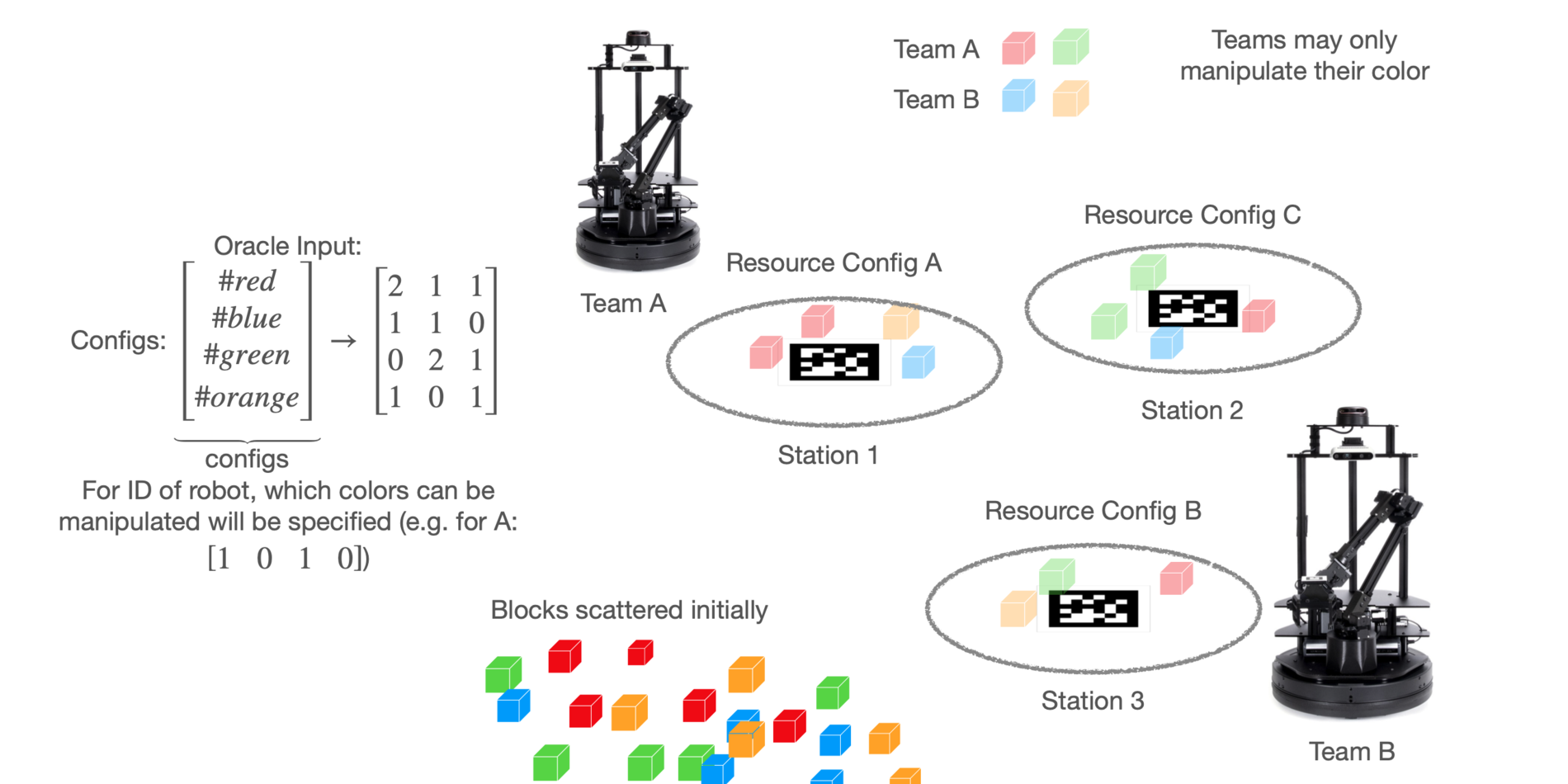
In the final project, teams of students will have their robots work as a team with robots programmed by other teams and where no explicit (digital) communication is allowed in a resource gathering task