
![]()
Apache NuttX is a lightweight Real-Time Operating System (RTOS) that runs on PINE64 PinePhone. Read the articles...
PinePhone Display
LCD Touch Panel
LVGL Graphics
Accelerometer and Gyroscope
4G LTE Modem
GPIO
UART
USB
Power Management Integrated Circuit
Interrupts
Boot Sequence
Arm64 Emulation
Build and Boot NuttX
Download NuttX Binaries
How It Started
Older Articles
Can AI Help?
What's NuttX? Why run it on PinePhone?
If we're new to NuttX, here's a gentle intro...
The following is a journal that documents the porting of NuttX to PinePhone. It looks super messy and unstructured, please read the articles (at the top of this page) instead.
Table of Contents
- NuttX Automated Daily Build for PinePhone
- NuttX on QEMU
- UART Driver for NuttX
- Boot NuttX on PinePhone
- Interrupt Controller
- Backlight and LEDs
- PinePhone Device Tree
- Zig on PinePhone
- PinePhone Display Driver
- Zig Driver for PinePhone MIPI DSI
- Compose MIPI DSI Long Packet in Zig
- Compose MIPI DSI Short Packet in Zig
- Compute Error Correction Code in Zig
- Compute Cyclic Redundancy Check in Zig
- Test PinePhone MIPI DSI Driver with QEMU
- Test Case for PinePhone MIPI DSI Driver
- Initialise ST7703 LCD Controller in Zig
- Test Zig Display Driver for PinePhone
- Display Engine in Allwinner A64
- Display Engine Mixers
- Render Colours
- Render Mandelbrot Set
- Animate Madelbrot Set
- Render Square Overlay
- Render Circle Overlay
- Test PinePhone Display Engine
- Display Engine Usage
- Other Display Engine Features
- Timing Controller in Allwinner A64
- Zig Driver for PinePhone Display Engine
- Test Zig Driver for PinePhone Display Engine
- Complete PinePhone Display Driver in Zig
- Add MIPI DSI to NuttX Kernel
- Test MIPI DSI for NuttX Kernel
- Test Timing Controller TCON0 Driver for NuttX Kernel
- Test Display Engine Driver for NuttX Kernel
- Missing Pixels in PinePhone Image
- Fix Missing Pixels in PinePhone Image
- Merge PinePhone into NuttX Mainline
- LVGL on NuttX on PinePhone
- PinePhone Touch Panel
- LVGL Terminal for NuttX
- PinePhone on NuttX becomes a Feature Phone
- USB Driver and LTE Modem Driver for PinePhone
- 4G LTE Modem
- PinePhone Accelerometer and Gyroscope
- Compile NuttX on Android with Termux
- Emulate PinePhone with Unicorn Emulator
- Simulate PinePhone UI with Zig, LVGL and WebAssembly
- Apache NuttX RTOS for PinePhone Pro
- Test Logs
- USB Devices on PinePhone
- Testing Zig Backlight Driver on PinePhone
- Testing Zig Display Engine Driver on PinePhone
- Testing Zig Display Engine Driver on QEMU
- Testing p-boot Display Engine on PinePhone
- Testing NuttX Zig Driver for MIPI DSI on PinePhone
- Testing NuttX Zig Driver for MIPI DSI on QEMU
- Testing p-boot Driver for MIPI DSI (with logging)
- Testing p-boot Driver for MIPI DSI (without logging)
- Testing Zig on PinePhone
- Testing GIC Version 2 on PinePhone
- Testing GIC Version 2 on QEMU
- Boot Files for Manjaro Phosh on PinePhone
- GIC Register Dump
NuttX for PinePhone is now built automatically every day via GitHub Actions.
The Daily Releases are available here...
nuttx.hash contains the Commit Hash of the NuttX Kernel and NuttX Apps repos...
NuttX Source: https://github.com/apache/nuttx/tree/4bb30ab0c136dc36182cf43995337fc1d44f0a37
NuttX Apps: https://github.com/apache/nuttx-apps/tree/5a4e9e4389264522d02dae78bcb3f9813743300f
The GitHub Actions Workflow is here...
Note: This section is outdated, please check this article for updates...
Apache NuttX RTOS now runs on Arm Cortex-A53 with Multi-Core SMP...
PinePhone is based on Allwinner A64 SoC with 4 Cores of Arm Cortex-A53...
We start with NuttX Mainline, run it on QEMU, then mod it for PinePhone.
Download the Source Code for NuttX Mainline, which supports Arm Cortex-A53...
## Create NuttX Directory
mkdir nuttx
cd nuttx

## Download NuttX OS
git clone \
    --recursive \
    --branch arm64 \
    https://github.com/lupyuen/incubator-nuttx \
    nuttx

## Download NuttX Apps
git clone \
    --recursive \
    --branch arm64 \
    https://github.com/lupyuen/incubator-nuttx-apps \
    apps

## We'll build NuttX inside nuttx/nuttx
cd nuttx
Install the Build Prerequisites, skip the RISC-V Toolchain...
Download the Arm Toolchain for AArch64 ELF Bare-Metal Target (aarch64-none-elf)...
For Linux x64 and WSL:
For macOS:
(I don't recommend building NuttX on Plain Old Windows CMD, please use WSL instead)
Add it to the PATH...
## For Linux x64 and WSL:
export PATH="$PATH:$HOME/gcc-arm-11.2-2022.02-x86_64-aarch64-none-elf/bin"

## For macOS:
export PATH="$PATH:/Applications/ArmGNUToolchain/11.3.rel1/aarch64-none-elf/bin"
Check the toolchain...
aarch64-none-elf-gcc -v(Based on the instructions here)
Download and install QEMU...
For macOS we may use brew...
brew install qemuFirst we build NuttX for a Single Core of Arm Cortex-A53...
## Configure NuttX for Single Core
./tools/configure.sh -l qemu-a53:nsh

## Build NuttX
make

## Dump the disassembly to nuttx.S
aarch64-none-elf-objdump \
  -t -S --demangle --line-numbers --wide \
  nuttx \
  >nuttx.S \
  2>&1
The NuttX Output Files may be found here...
This is how we test NuttX on QEMU with a Single Core of Arm Cortex-A53...
## Start QEMU (Single Core) with NuttX
qemu-system-aarch64 \
  -cpu cortex-a53 \
  -nographic \
  -machine virt,virtualization=on,gic-version=3 \
  -net none \
  -chardev stdio,id=con,mux=on \
  -serial chardev:con \
  -mon chardev=con,mode=readline \
  -kernel ./nuttx
Here's NuttX with a Single Core running on QEMU...
- Ready to Boot CPU
- Boot from EL2
- Boot from EL1
- Boot to C runtime for OS Initialize

nx_start: Entry
up_allocate_heap: heap_start=0x0x402c4000, heap_size=0x7d3c000
gic_validate_dist_version: GICv3 version detect
gic_validate_dist_version: GICD_TYPER = 0x37a0007
gic_validate_dist_version: 224 SPIs implemented
gic_validate_dist_version: 0 Extended SPIs implemented
gic_validate_dist_version: Distributor has no Range Selector support
gic_validate_redist_version: GICD_TYPER = 0x1000011
gic_validate_redist_version: 16 PPIs implemented
gic_validate_redist_version: no VLPI support, no direct LPI support
up_timer_initialize: up_timer_initialize: cp15 timer(s) running at 62.50MHz, cycle 62500
uart_register: Registering /dev/console
uart_register: Registering /dev/ttyS0
work_start_highpri: Starting high-priority kernel worker thread(s)
nx_start_application: Starting init thread
lib_cxx_initialize: _sinit: 0x402a7000 _einit: 0x402a7000 _stext: 0x40280000 _etext: 0x402a8000
nsh: sysinit: fopen failed: 2
nsh: mkfatfs: command not found

NuttShell (NSH) NuttX-10.3.0-RC2
nsh> nx_start: CPU0: Beginning Idle Loop

nsh> help
help usage:  help [-v] [<cmd>]

  .         cd        dmesg     help      mount     rmdir     true      xd
  [         cp        echo      hexdump   mv        set       truncate
  ?         cmp       exec      kill      printf    sleep     uname
  basename  dirname   exit      ls        ps        source    umount
  break     dd        false     mkdir     pwd       test      unset
  cat       df        free      mkrd      rm        time      usleep

Builtin Apps:
  getprime  hello     nsh       ostest    sh

nsh> uname -a
NuttX 10.3.0-RC2 1e8f2a8 Aug 23 2022 07:04:54 arm64 qemu-a53

nsh> hello
task_spawn: name=hello entry=0x4029b594 file_actions=0x402c9580 attr=0x402c9588 argv=0x402c96d0
spawn_execattrs: Setting policy=2 priority=100 for pid=3
Hello, World!!

nsh> ls /
/:
 dev/
 etc/
 proc/

nsh> ls /dev
/dev:
 console
 null
 ram0
 ram2
 ttyS0
 zero

nsh> ls /proc
/proc:
 0/
 1/
 2/
 meminfo
 memdump
 fs/
 self/
 uptime
 version

nsh> ls /etc
/etc:
 init.d/

nsh> ls /etc/init.d
/etc/init.d:
 rcS

nsh> cat /etc/init.d/rcS
# Create a RAMDISK and mount it at /tmp

mkrd -m 2 -s 512 1024
mkfatfs /dev/ram2
mount -t vfat /dev/ram2 /tmp
NuttX is POSIX Compliant, so the developer experience feels very much like Linux. (But much smaller)
And NuttX runs everything in RAM, no File System needed. (For now)
From Single Core to Multi Core! Now we build NuttX for 4 Cores of Arm Cortex-A53...
## Erase the NuttX Configuration
make distclean

## Configure NuttX for 4 Cores
./tools/configure.sh -l qemu-a53:nsh_smp

## Build NuttX
make

## Dump the disassembly to nuttx.S
aarch64-none-elf-objdump \
  -t -S --demangle --line-numbers --wide \
  nuttx \
  >nuttx.S \
  2>&1
The NuttX Output Files may be found here...
And this is how we test NuttX on QEMU with 4 Cores of Arm Cortex-A53...
## Start QEMU (4 Cores) with NuttX
qemu-system-aarch64 \
  -smp 4 \
  -cpu cortex-a53 \
  -nographic \
  -machine virt,virtualization=on,gic-version=3 \
  -net none \
  -chardev stdio,id=con,mux=on \
  -serial chardev:con \
  -mon chardev=con,mode=readline \
  -kernel ./nuttx
Note that smp is set to 4. (Symmetric Multi-Processing)
Here's NuttX with 4 Cores running on QEMU...
- Ready to Boot CPU
- Boot from EL2
- Boot from EL1
- Boot to C runtime for OS Initialize

[CPU0] psci_detect: Detected PSCI v1.1
[CPU0] nx_start: Entry
[CPU0] up_allocate_heap: heap_start=0x0x402db000, heap_size=0x7d25000
[CPU0] gic_validate_dist_version: GICv3 version detect
[CPU0] gic_validate_dist_version: GICD_TYPER = 0x37a0007
[CPU0] gic_validate_dist_version: 224 SPIs implemented
[CPU0] gic_validate_dist_version: 0 Extended SPIs implemented
[CPU0] gic_validate_dist_version: Distributor has no Range Selector support
[CPU0] gic_validate_redist_version: GICD_TYPER = 0x1000001
[CPU0] gic_validate_redist_version: 16 PPIs implemented
[CPU0] gic_validate_redist_version: no VLPI support, no direct LPI support
[CPU0] up_timer_initialize: up_timer_initialize: cp15 timer(s) running at 62.50MHz, cycle 62500
[CPU0] uart_register: Registering /dev/console
[CPU0] uart_register: Registering /dev/ttyS0

- Ready to Boot CPU
- Boot from EL2
- Boot from EL1
- Boot to C runtime for OS Initialize

[CPU1] gic_validate_redist_version: GICD_TYPER = 0x101000101
[CPU1] gic_validate_redist_version: 16 PPIs implemented
[CPU1] gic_validate_redist_version: no VLPI support, no direct LPI support
[CPU1] nx_idle_trampoline: CPU1: Beginning Idle Loop
[CPU0] arm64_start_cpu: Secondary CPU core 1 (MPID:0x1) is up

- Ready to Boot CPU
- Boot from EL2
- Boot from EL1
- Boot to C runtime for OS Initialize

[CPU2] gic_validate_redist_version: GICD_TYPER = 0x201000201
[CPU2] gic_validate_redist_version: 16 PPIs implemented
[CPU2] gic_validate_redist_version: no VLPI support, no direct LPI support
[CPU2] nx_idle_trampoline: CPU2: Beginning Idle Loop
[CPU0] arm64_start_cpu: Secondary CPU core 2 (MPID:0x2) is up

- Ready to Boot CPU
- Boot from EL2
- Boot from EL1
- Boot to C runtime for OS Initialize

[CPU3] gic_validate_redist_version: GICD_TYPER = 0x301000311
[CPU3] gic_validate_redist_version: 16 PPIs implemented
[CPU3] gic_validate_redist_version: no VLPI support, no direct LPI support
[CPU0] arm64_start_cpu: Secondary CPU core 3 (MPID:0x3) is up
[CPU0] work_start_highpri: Starting high-priority kernel worker thread(s)
[CPU0] nx_start_application: Starting init thread
[CPU3] nx_idle_trampoline: CPU3: Beginning Idle Loop
[CPU0] nx_start: CPU0: Beginning Idle Loop

nsh: sysinit: fopen failed: 2
nsh: mkfatfs: command not found

NuttShell (NSH) NuttX-10.3.0-RC2
nsh> help
help usage:  help [-v] [<cmd>]

  .         cd        dmesg     help      mount     rmdir     true      xd
  [         cp        echo      hexdump   mv        set       truncate
  ?         cmp       exec      kill      printf    sleep     uname
  basename  dirname   exit      ls        ps        source    umount
  break     dd        false     mkdir     pwd       test      unset
  cat       df        free      mkrd      rm        time      usleep

Builtin Apps:
  getprime  hello     nsh       ostest    sh        smp       taskset

nsh> uname -a
NuttX 10.3.0-RC2 1e8f2a8 Aug 21 2022 15:57:35 arm64 qemu-a53

nsh> hello
[CPU0] task_spawn: name=hello entry=0x4029cee4 file_actions=0x402e52b0 attr=0x402e52b8 argv=0x402e5400
[CPU0] spawn_execattrs: Setting policy=2 priority=100 for pid=6
Hello, World!
We see each of the 4 Cores starting NuttX (CPU0 to CPU3). That's so cool!
(Can we use QEMU to partially emulate PinePhone? That would be extremely helpful!)
Now we browse the Source Files for the implementation of Cortex-A53 on NuttX.
NuttX treats QEMU as a Target Board (as though it was a dev board). Here are the Source Files and Build Configuration for the QEMU Board...
(We'll clone this to create a Target Board for PinePhone)
The Board-Specific Drivers for QEMU are started in qemu-a53/src/qemu_bringup.c
(We'll start the PinePhone Drivers here)
The QEMU Board calls the QEMU Architecture-Specific Drivers at...
The UART Driver is located at qemu/qemu_serial.c and qemu/qemu_lowputc.S
(For PinePhone we'll create a UART Driver for Allwinner A64 SoC. I2C, SPI and other Low-Level A64 Drivers will be located here too)
The QEMU Functions (Board and Architecture) call the Arm64 Architecture Functions at...
Which implements all kinds of Arm64 Features: FPU, Interrupts, MMU, Tasks, Timers...
(We'll reuse them for PinePhone)
Next we analyse the NuttX Image with Ghidra, to understand the NuttX Image Header and Startup Code.
Here's the NuttX ELF Image nuttx analysed by Ghidra...
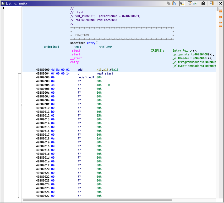
Note that the NuttX Image jumps to real_start (to skip the Image Header)...
40280000 4d 5a 00 91     add        x13,x18,#0x16
40280004 0f 00 00 14     b          real_start
real_start is defined at 0x4028 0040 with the Startup Code...
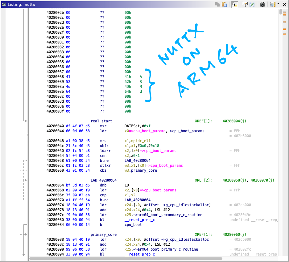
We see something interesting: The Magic Number ARM\x64 appears at address 0x4028 0038.
Searching the net for this Magic Number reveals that it's actually an Arm64 Linux Kernel Header!
When we refer to the NuttX Arm64 Disassembly nuttx.S, we find happiness: arch/arm64/src/common/arm64_head.S
    /* Kernel startup entry point.
     * ---------------------------
     *
     * The requirements are:
     *   MMU = off, D-cache = off, I-cache = on or off,
     *   x0 = physical address to the FDT blob.
     *       it will be used when NuttX support device tree in the future
     *
     * This must be the very first address in the loaded image.
     * It should be loaded at any 4K-aligned address.
     */
    .globl __start;
__start:

    /* DO NOT MODIFY. Image header expected by Linux boot-loaders.
     *
     * This add instruction has no meaningful effect except that
     * its opcode forms the magic "MZ" signature of a PE/COFF file
     * that is required for UEFI applications.
     *
     * Some bootloader (such imx8 uboot) checking the magic "MZ" to see
     * if the image is a valid Linux image. but modifying the bootLoader is
     * unnecessary unless we need to do a customize secure boot.
     * so just put the ''MZ" in the header to make bootloader happiness
     */

    add     x13, x18, #0x16      /* the magic "MZ" signature */
    b       real_start           /* branch to kernel start */
    .quad   0x480000              /* Image load offset from start of RAM */
    .quad   _e_initstack - __start         /* Effective size of kernel image, little-endian */
    .quad   __HEAD_FLAGS         /* Informative flags, little-endian */
    .quad   0                    /* reserved */
    .quad   0                    /* reserved */
    .quad   0                    /* reserved */
    .ascii  "ARM\x64"            /* Magic number, "ARM\x64" */
    .long   0                    /* reserved */

real_start:
    /* Disable all exceptions and interrupts */
NuttX Image actually follows the Arm64 Linux Kernel Image Format! As defined here...
Arm64 Linux Kernel Image contains a 64-byte header...
u32 code0;                    /* Executable code */
u32 code1;                    /* Executable code */
u64 text_offset;              /* Image load offset, little endian */
u64 image_size;               /* Effective Image size, little endian */
u64 flags;                    /* kernel flags, little endian */
u64 res2      = 0;            /* reserved */
u64 res3      = 0;            /* reserved */
u64 res4      = 0;            /* reserved */
u32 magic     = 0x644d5241;   /* Magic number, little endian, "ARM\x64" */
u32 res5;                     /* reserved (used for PE COFF offset) */
Start of RAM is 0x4000 0000. The Image Load Offset in our NuttX Image Header is 0x48 0000 according to arch/arm64/src/common/arm64_head.S
.quad 0x480000 /* Image load offset from start of RAM */
This means that our NuttX Image will be loaded at 0x4048 0000.
I wonder if this Image Load Offset should have been 0x28 0000? (Instead of 0x48 0000)
Remember that Ghidra (and the Arm Disassembly) says that our NuttX Image is actually loaded at 0x4028 0000. (Instead of 0x4048 0000)
RAM Size and RAM Start are defined in the NuttX Configuration: boards/arm64/qemu/qemu-a53/configs/nsh_smp/defconfig
CONFIG_RAM_SIZE=134217728
CONFIG_RAM_START=0x40000000
That's 128 MB RAM. Which should fit inside PinePhone's 2 GB RAM.
The NuttX Image was built with this Linker Command, based on make --trace...
aarch64-none-elf-ld \
  --entry=__start \
  -nostdlib \
  --cref \
  -Map=nuttx/nuttx/nuttx.map \
  -Tnuttx/nuttx/boards/arm64/qemu/qemu-a53/scripts/dramboot.ld  \
  -L nuttx/nuttx/staging \
  -L nuttx/nuttx/arch/arm64/src/board  \
  -o nuttx/nuttx/nuttx arm64_head.o  \
  --start-group \
  -lsched \
  -ldrivers \
  -lboards \
  -lc \
  -lmm \
  -larch \
  -lapps \
  -lfs \
  -lbinfmt \
  -lboard /Applications/ArmGNUToolchain/11.3.rel1/aarch64-none-elf/bin/../lib/gcc/aarch64-none-elf/11.3.1/libgcc.a /Applications/ArmGNUToolchain/11.3.rel1/aarch64-none-elf/bin/../lib/gcc/aarch64-none-elf/11.3.1/../../../../aarch64-none-elf/lib/libm.a \
  --end-group
NuttX Image begins at __start, which is defined as 0x4028 0000 in the NuttX Linker Script: boards/arm64/qemu/qemu-a53/scripts/dramboot.ld
SECTIONS
{
  . = 0x40280000;  /* uboot load address */
  _start = .;
We'll change this to 0x4008 0000 for PinePhone, since Kernel Start Address is 0x4008 0000 and Image Load Offset is 0. (See below)
We've seen the NuttX Image (which looks like a Linux Kernel Image), let's compare with a PinePhone Linux Kernel Image and see how NuttX needs to be tweaked...
Will NuttX run on PinePhone? Let's analyse a PinePhone Linux Kernel Image with Ghidra, to look at the Linux Kernel Header and Startup Code.
We'll use the PinePhone Jumpdrive Image, since it's small...
https://github.com/dreemurrs-embedded/Jumpdrive
Download https://github.com/dreemurrs-embedded/Jumpdrive/releases/download/0.8/pine64-pinephone.img.xz
Expand pine64-pinephone.img.xz
Expand the files inside...
gunzip Image.gz
gunzip initramfs.gz
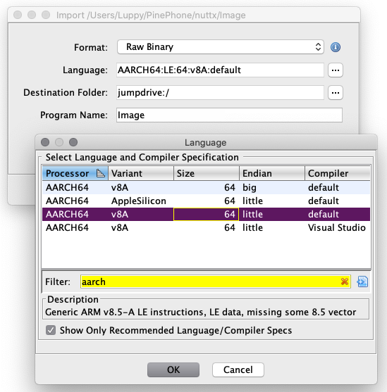
tar xvf initramfsImport the uncompressed Image (Linux Kernel) into Ghidra.
For "Language" select AARCH64:LE:v8A:default...
- Processor: AARCH64
- Variant: v8A
- Size: 64
- Endian: little
- Compiler: default
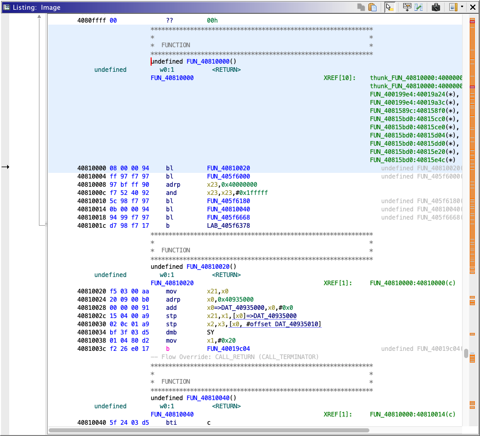
Here's the Jumpdrive Image (Linux Kernel) in Ghidra...

According to the Linux Kernel Header...
We see Linux Kernel Magic Number ARM\x64 at offset 0x38.
Image Load Offset is 0, according to the header.
Kernel Start Address on PinePhone is 0x4008 0000.
So we shift Image in Ghidra to start at 0x4008 0000...
-
Click Window > Memory Map
-
Click "ram"
-
Click the 4-Arrows icon ("Move a block to another address")
-
Change "New Start Address" to 40080000
So will NuttX boot on PinePhone?
It's highly plausible! We discovered (with happiness) that NuttX already generates an Arm64 Linux Kernel Header.
So NuttX could be a drop-in replacement for the PinePhone Linux Kernel! We just need to...
-
Write PinePhone Jumpdrive to a microSD Card (with Etcher, in FAT format)
-
Overwrite
Image.gzby the (gzipped) NuttX Binary Imagenuttx.bin.gz -
Insert the microSD Card into PinePhone
-
Power on PinePhone
And NuttX should (theoretically) boot on PinePhone!
As mentioned earlier, we should rebuild NuttX so that __start is changed to 0x4008 0000 (from 0x4028 0000), as defined in the NuttX Linker Script: boards/arm64/qemu/qemu-a53/scripts/dramboot.ld
SECTIONS
{
SECTIONS
{
  . = 0x40080000;  /* PinePhone uboot load address (kernel_addr_r) */
  /* Previously: . = 0x40280000; */  /* uboot load address */
  _start = .;
Also the Image Load Offset in our NuttX Image Header should be changed to 0x0 (from 0x48 0000): arch/arm64/src/common/arm64_head.S
    .quad   0x0000               /* PinePhone Image load offset from start of RAM */
    # Previously: .quad   0x480000              /* Image load offset from start of RAM */
Later we'll increase the RAM Size to 2 GB (from 128 MB): boards/arm64/qemu/qemu-a53/configs/nsh_smp/defconfig
/* TODO: Increase to 2 GB for PinePhone */
CONFIG_RAM_SIZE=134217728
CONFIG_RAM_START=0x40000000
But not right now, because it might clash with the Device Tree and RAM File System.
But will we see anything when NuttX boots on PinePhone?
Not yet. We'll need to implement the UART Driver for NuttX...
Read the article...
We won't see any output from NuttX until we implement the UART Driver for NuttX.
These are the Source Files for the QEMU UART Driver (PL011)...
We'll replace the code above with the UART Driver for Allwinner A64 SoC...
To access the UART Port on PinePhone, we'll use this USB Serial Debug Cable...
Which connects to the Headphone Port. Genius!
(Remember to flip the Headphone Switch to OFF)

PinePhone UART Port in disguise
The log appears garbled when printf is called by our NuttX Test Apps, due to concurrent printing by multiple tasks...
nx_start_application: Starting init thread
lib_cxx_initialize: _sinit: 0x400e9000 _einit: 0x400e9000
nsh: sysinit: fopen failed: 2
nshn:x _msktfaarttf:s :C PcUo0m:m aBnedg innonti nfgo uInddleLoNouptt
Shell (NSH) NuttX-11.0.0-RC2
It's supposed to show...
nsh: sysinit: fopen failed: 2
nsh: mkfatfs: command not found
NuttShell (NSH) NuttX-11.0.0-RC2
nsh> nx_start: CPU0: Beginning Idle Loop
Why is the output garbled?
The output is garbled because there 2 ways of writing to the Console Output...
-
up_putc: Called by the NuttX Kernel to log messages (like_info) -
a64_uart_send: Allwinner A64 UART Driver is called by NuttX Apps to print messages (likeprintf)
To fix the output garbled at startup: Disable "Scheduler Informational Output" in...
"Build Setup > Debug Options > Enable Debug Features > Scheduler Debug Features"
This prevents sinfo from garbling the printf output...
-
sinfowrites directly to UART Port character by character...nx_start: CPU0: Beginning Idle Loop -
Whereas
printfis buffered and writes the buffer to the UART Driver...nsh: mkfatfs: command not found NuttShell (NSH) NuttX-11.0.0-RC2
Also we have a temporary workaround until this gets fixed: a64_serial.c
static void a64_uart_send(struct uart_dev_s *dev, int ch)
{
const struct a64_uart_port_s *port = (struct a64_uart_port_s *)dev->priv;
const struct a64_uart_config *config = &port->config;
#define BUFFER_UART
#ifdef BUFFER_UART
//// TODO: Fix the garbled output. Buffer the chars until we see CR or LF.
static char buf[256];
static int pos = 0;
if (ch != '>' && ch != '\r' && ch != '\n' && pos < sizeof(buf))
{
buf[pos] = ch;
pos += 1;
return;
}
for (int i = 0; i < pos; i++)
{
up_putc(buf[i]);
}
pos = 0;
up_putc(ch);
UNUSED(config);
#else
/* Write char to Transmit Holding Register (UART_THR) */
putreg8(ch, UART_THR(config->uart));
#endif // BUFFER_UART
}This forces a64_uart_send to call up_putc to print an entire line of text. (Instead of character by character)
This also means that the nsh prompt will no longer echo text character by character. We need to press Enter to see the nsh output.
FYI: printf Console Output Stream is locked and unlocked with a Mutex. Let's log the locking and unlocking of the Mutex...
nuttx/libs/libc/stdio/lib_libfilelock.c
void flockfile(FAR struct file_struct *stream)
{
up_putc('{'); // Log the Mutex Locking
nxrmutex_lock(&stream->fs_lock);
}
...
void funlockfile(FAR struct file_struct *stream)
{
up_putc('}'); // Log the Mutex Unlocking
nxrmutex_unlock(&stream->fs_lock);
}Output log shows that { and } (Mutex Locking and Unlocking) are nested...
nx_start_application: Starting init thread
lib_cxx_initialize: _sinit: 0x400e9000 _einit: 0x400e9000
{{{}}{{}}{{}}{{}}{{}}{{}}{{}}{{}}{{}}{{}}{{}}{{}}{{}}{{}}{{}}{{}}{{}}{{}}{{}}{{}}{{}}{{}}{{}}{{}}{{}}{{}}{{}}{{}}{{}}{{}}{n}s}h{:} {s}y{s}i{n}i{t}:{ }f{o}p{e}n{ }f{a}i{l}e{d}:{ }2{
}
{}{}{}{}{}{}{}{}{}{}{}{}{}{}{}{}{}{}{}{}{}{}{}{}{}{}{}{}{}{}{}{}{}{}{}{}{}{}{}{}{}{}{}{}{}{}{}{}{}{}{}{}{}{}{}{}{}{}{}{}{}{}{}{}{}{}{}{}{}{}{}{}{}{}{}{{{}}{{}}{{}}{{}}{{}}{{}}{{}}{{}}{{}}{{}}{{}}{{}}{{}}{{}}{{}}{{}}{{}}{{}}{{}}{{}}{{}}{{}}{{}}{{}}{{}}{{}}{{}}{{}}{{}}{{}}{{}}{{}}{n}s}h{:} {m{k}f}a{t}f{s{:} }c{o{m}m}a{n{d} }n{o{t} }f{o{u}n}d{
How can be it locked twice without unlocking?
nxrmutex_lock calls...
nxmutex_lock, which calls...nxsem_wait, which calls...up_switch_context
Let's print the Thread ID and Mutex Count...
void flockfile(FAR struct file_struct *stream)
{
nxrmutex_lock(&stream->fs_lock);
_info("%p, thread=%d, mutex.count=%d\n", stream, gettid(), stream->fs_lock.count); // Log the Thread ID and Mutex Count
}
void funlockfile(FAR struct file_struct *stream)
{
_info("%p, thread=%d, mutex.count=%d\n", stream, gettid(), stream->fs_lock.count); // Log the Thread ID and Mutex Count
nxrmutex_unlock(&stream->fs_lock);
}
Thread ID is always the same. Mutex Count goes from 1 to 3 and drops to 2...
lib_cxx_initialize: _sinit: 0x400e9000 _einit: 0x400e9000
flockfile: 0x40a5cc78, thread=2, mutex.count=1
flockfile: 0x40a5cc78, thread=2, mutex.count=2
flockfile: 0x40a5cc78, thread=2, mutex.count=3
funlockfile: 0x40a5cc78, thread=2, mutex.count=3
funlockfile: 0x40a5cc78, thread=2, mutex.count=2
Why? That's because nxrmutex_lock allows the Mutex to be locked multiple times within the same thread.
FYI: Here's how we verify whether our code is called by multiple CPU Cores...
#include "../arch/arm64/src/common/arm64_arch.h"
_info("up_cpu_index=%d\n", MPIDR_TO_CORE(GET_MPIDR()));
// Shows: `up_cpu_index=0`
_info("mpidr_el1=%p\n", read_sysreg(mpidr_el1));
// Shows `mpidr_el1=0x80000000`FYI: How printf works...
printf calls...
vfprintf, which calls...libvsprintf, which calls...vsprintf_internal, which calls...stream_putc, which calls...- ???, which calls...
fputc, which calls...libfwrite
fputc also calls...
To support multiple UART Ports, we copied the following functions from the Allwinner A1X UART Driver...
-
(Init the UART Ports)
-
(Init the UART Pins. Called by
arm64_earlyserialinit) -
(Configure the UART Port. Called when the UART Port is opened)
-
(UART Interrupt Handler)
-
(Receive UART Data)
Inside the UART Driver, be careful when logging to the UART Port!
If the UART Port is busy doing logging, it won't allow us to the Baud Rate...
"This register may only be accessed when the DLAB bit (UART_LCR[7]) is set and the UART is not busy (UART_USR[0] is zero)"
(Allwinner A64 User Manual, Page 564)
That's why we always wait for UART Not Busy before setting the Baud Rate. (Like this)
What happens if UART Is Busy when we set the Baud Rate?
up_setup: Enter DLAB=1
up_serialout: addr=0x1c2800c, before=0x3, after=0x83
up_setup: Set the BAUD divisor
up_serialout: addr=0x1c28004, before=0x0, after=0x0
up_serialout: addr=0x1c28000, before=0x0, after=0xd
up_setup: Clear DLAB
up_serialout: addr=0x1c2800c, before=0x3, after=0x3
From above, we see that the Baud Rate is not read correctly...
up_serialout: addr=0x1c28000, before=0x0, after=0xd
// For UART0: Before should be 0xd
And DLAB doesn't get cleared correctly...
up_setup: Enter DLAB=1
up_serialout: addr=0x1c2800c, before=0x3, after=0x83
...
up_setup: Clear DLAB
up_serialout: addr=0x1c2800c, before=0x3, after=0x3
// Before should be 0x83, not 0x3
We fix this by disabling the logging and waiting for UART Not Busy before setting the Baud Rate. (Like this)
The changes have been upstreamed to NuttX Mainline...
How do we enable a UART Port? Like UART3?
Head over to the NuttX Build Configuration...
make menuconfigThen select...
- System Type > Allwinner A64 Peripheral Selection > UART3
To configure the Baud Rate, Parity and Stop Bits...
- Device Drivers > Serial Driver Support > UART3 Configuration
(The default Baud Rate / Bits / Parity / Stop Bits work OK with the PinePhone LTE Modem on UART3: 115.2 kbps / 8 Bits / No Parity / 1 Stop Bit)
Let's test the PinePhone LTE Modem on UART3...
In the previous section we have configured UART3 for PinePhone's 4G LTE Modem.
This is how we read and write the UART3 port via /dev/ttyS1: hello_main.c
// Open /dev/ttyS1 (UART3)
int fd = open("/dev/ttyS1", O_RDWR);
printf("Open /dev/ttyS1: fd=%d\n", fd);
assert(fd > 0);
// Repeat 5 times: Write command and read response
for (int i = 0; i < 5; i++) {
// Write command
const char cmd[] = "AT\r";
ssize_t nbytes = write(fd, cmd, sizeof(cmd));
printf("Write command: nbytes=%ld\n", nbytes);
assert(nbytes == sizeof(cmd));
// Read response
static char buf[1024];
nbytes = read(fd, buf, sizeof(buf) - 1);
if (nbytes >= 0) { buf[nbytes] = 0; }
printf("Response: nbytes=%ld\n%s\n", nbytes, buf);
// Wait a while
sleep(2);
}
// Close the device
close(fd);LTE Modem works OK with UART3 on NuttX yay! See the test log here...
Note: Modem UART flow control is broken
"Not resolved in v1.2 -- assumption is that USB will be used for high-bandwidth modem I/O.
BB-TX and BB-RX are connected to UART3 (PD0/PD1). BB-RTS and BB-CTS are connected to UART4 (PD4/PD5). To use hardware flow control, TX/RX would need to be connected to UART4, swapping PD0/PD1 with the motor control and rear camera reset GPIOs at PD2/PD3. This would need a device tree change.
Hardware flow control can be disabled with the AT+IFC command, and USB can also be used for commands instead of the UART. So the impact of this problem is unclear."
Read the article...
Before starting the Linux Kernel, PinePhone boots by running the U-Boot Bootloader...
Here's the PinePhone U-Boot Log captured with the USB Serial Debug Cable...
(Press Enter repeatedly when PinePhone powers on to enter the U-Boot Prompt)
$ screen /dev/ttyUSB0 115200
DRAM: 2048 MiB
Trying to boot from MMC1
NOTICE: BL31: v2.2(release):v2.2-904-gf9ea3a629
NOTICE: BL31: Built : 15:32:12, Apr 9 2020
NOTICE: BL31: Detected Allwinner A64/H64/R18 SoC (1689)
NOTICE: BL31: Found U-Boot DTB at 0x4064410, model: PinePhone
NOTICE: PSCI: System suspend is unavailable
U-Boot 2020.07 (Nov 08 2020 - 00:15:12 +0100)
DRAM: 2 GiB
MMC: Device 'mmc@1c11000': seq 1 is in use by 'mmc@1c10000'
mmc@1c0f000: 0, mmc@1c10000: 2, mmc@1c11000: 1
Loading Environment from FAT... *** Warning - bad CRC, using default environment
starting USB...
No working controllers found
Hit any key to stop autoboot:
=> help
? - alias for 'help'
base - print or set address offset
bdinfo - print Board Info structure
blkcache - block cache diagnostics and control
boot - boot default, i.e., run 'bootcmd'
bootd - boot default, i.e., run 'bootcmd'
bootelf - Boot from an ELF image in memory
booti - boot Linux kernel 'Image' format from memory
bootm - boot application image from memory
bootvx - Boot vxWorks from an ELF image
cmp - memory compare
coninfo - print console devices and information
cp - memory copy
crc32 - checksum calculation
dm - Driver model low level access
echo - echo args to console
editenv - edit environment variable
env - environment handling commands
exit - exit script
ext2load - load binary file from a Ext2 filesystem
ext2ls - list files in a directory (default /)
ext4load - load binary file from a Ext4 filesystem
ext4ls - list files in a directory (default /)
ext4size - determine a file's size
false - do nothing, unsuccessfully
fatinfo - print information about filesystem
fatload - load binary file from a dos filesystem
fatls - list files in a directory (default /)
fatmkdir - create a directory
fatrm - delete a file
fatsize - determine a file's size
fatwrite - write file into a dos filesystem
fdt - flattened device tree utility commands
fstype - Look up a filesystem type
go - start application at address 'addr'
gpio - query and control gpio pins
gpt - GUID Partition Table
gzwrite - unzip and write memory to block device
help - print command description/usage
iminfo - print header information for application image
imxtract - extract a part of a multi-image
itest - return true/false on integer compare
ln - Create a symbolic link
load - load binary file from a filesystem
loadb - load binary file over serial line (kermit mode)
loads - load S-Record file over serial line
loadx - load binary file over serial line (xmodem mode)
loady - load binary file over serial line (ymodem mode)
loop - infinite loop on address range
ls - list files in a directory (default /)
lzmadec - lzma uncompress a memory region
md - memory display
mm - memory modify (auto-incrementing address)
mmc - MMC sub system
mmcinfo - display MMC info
mw - memory write (fill)
nm - memory modify (constant address)
part - disk partition related commands
poweroff - Perform POWEROFF of the device
printenv - print environment variables
random - fill memory with random pattern
reset - Perform RESET of the CPU
run - run commands in an environment variable
save - save file to a filesystem
saveenv - save environment variables to persistent storage
setenv - set environment variables
setexpr - set environment variable as the result of eval expression
sf - SPI flash sub-system
showvar - print local hushshell variables
size - determine a file's size
sleep - delay execution for some time
source - run script from memory
sysboot - command to get and boot from syslinux files
test - minimal test like /bin/sh
true - do nothing, successfully
unlz4 - lz4 uncompress a memory region
unzip - unzip a memory region
usb - USB sub-system
usbboot - boot from USB device
version - print monitor, compiler and linker version
=> printenv
arch=arm
baudrate=115200
board=sunxi
board_name=sunxi
boot_a_script=load ${devtype} ${devnum}:${distro_bootpart} ${scriptaddr} ${prefix}${script}; source ${scriptaddr}
boot_extlinux=sysboot ${devtype} ${devnum}:${distro_bootpart} any ${scriptaddr} ${prefix}${boot_syslinux_conf}
boot_net_usb_start=usb start
boot_prefixes=/ /boot/
boot_script_dhcp=boot.scr.uimg
boot_scripts=boot.scr.uimg boot.scr
boot_syslinux_conf=extlinux/extlinux.conf
boot_targets=fel mmc_auto usb0
bootcmd=run distro_bootcmd
bootcmd_fel=if test -n ${fel_booted} && test -n ${fel_scriptaddr}; then echo '(FEL boot)'; source ${fel_scriptaddr}; fi
bootcmd_mmc0=devnum=0; run mmc_boot
bootcmd_mmc1=devnum=1; run mmc_boot
bootcmd_mmc_auto=if test ${mmc_bootdev} -eq 1; then run bootcmd_mmc1; run bootcmd_mmc0; elif test ${mmc_bootdev} -eq 0; then run bootcmd_mmc0; run bootcmd_mmc1; fi
bootcmd_usb0=devnum=0; run usb_boot
bootdelay=0
bootm_size=0xa000000
console=ttyS0,115200
cpu=armv8
dfu_alt_info_ram=kernel ram 0x40080000 0x1000000;fdt ram 0x4FA00000 0x100000;ramdisk ram 0x4FE00000 0x4000000
distro_bootcmd=for target in ${boot_targets}; do run bootcmd_${target}; done
ethaddr=02:ba:8c:73:bf:ca
fdt_addr_r=0x4FA00000
fdtcontroladdr=bbf4dd40
fdtfile=allwinner/sun50i-a64-pinephone.dtb
kernel_addr_r=0x40080000
mmc_boot=if mmc dev ${devnum}; then devtype=mmc; run scan_dev_for_boot_part; fi
mmc_bootdev=0
partitions=name=loader1,start=8k,size=32k,uuid=${uuid_gpt_loader1};name=loader2,size=984k,uuid=${uuid_gpt_loader2};name=esp,size=128M,bootable,uuid=${uuid_gpt_esp};name=system,size=-,uuid=${uuid_gpt_system};
preboot=usb start
pxefile_addr_r=0x4FD00000
ramdisk_addr_r=0x4FE00000
scan_dev_for_boot=echo Scanning ${devtype} ${devnum}:${distro_bootpart}...; for prefix in ${boot_prefixes}; do run scan_dev_for_extlinux; run scan_dev_for_scripts; done;
scan_dev_for_boot_part=part list ${devtype} ${devnum} -bootable devplist; env exists devplist || setenv devplist 1; for distro_bootpart in ${devplist}; do if fstype ${devtype} ${devnum}:${distro_bootpart} bootfstype; then run scan_dev_for_boot; fi; done; setenv devplist
scan_dev_for_extlinux=if test -e ${devtype} ${devnum}:${distro_bootpart} ${prefix}${boot_syslinux_conf}; then echo Found ${prefix}${boot_syslinux_conf}; run boot_extlinux; echo SCRIPT FAILED: continuing...; fi
scan_dev_for_scripts=for script in ${boot_scripts}; do if test -e ${devtype} ${devnum}:${distro_bootpart} ${prefix}${script}; then echo Found U-Boot script ${prefix}${script}; run boot_a_script; echo SCRIPT FAILED: continuing...; fi; done�
scriptaddr=0x4FC00000
serial#=92c07dba8c73bfca
soc=sunxi
stderr=serial@1c28000
stdin=serial@1c28000
stdout=serial@1c28000
usb_boot=usb start; if usb dev ${devnum}; then devtype=usb; run scan_dev_for_boot_part; fi
uuid_gpt_esp=c12a7328-f81f-11d2-ba4b-00a0c93ec93b
uuid_gpt_system=b921b045-1df0-41c3-af44-4c6f280d3fae
Environment size: 2861/131068 bytes
=> boot
switch to partitions #0, OK
mmc0 is current device
Scanning mmc 0:1...
Found U-Boot script /boot.scr
653 bytes read in 3 ms (211.9 KiB/s)
## Executing script at 4fc00000
gpio: pin 114 (gpio 114) value is 1
4275261 bytes read in 192 ms (21.2 MiB/s)
Uncompressed size: 10170376 = 0x9B3008
36162 bytes read in 4 ms (8.6 MiB/s)
1078500 bytes read in 51 ms (20.2 MiB/s)
## Flattened Device Tree blob at 4fa00000
Booting using the fdt blob at 0x4fa00000
Loading Ramdisk to 49ef8000, end 49fff4e4 ... OK
Loading Device Tree to 0000000049eec000, end 0000000049ef7d41 ... OK
Starting kernel ...
/ #
According to the U-Boot Log, the Start of RAM kernel_addr_r is 0x4008 0000.
We need to set this in the NuttX Linker Script and the NuttX Header...
In the previous section, U-Boot says that the Start of RAM kernel_addr_r is 0x4008 0000.
Let's set this in the NuttX Linker Script and the NuttX Header...
-
Change Image Load Offset in NuttX Header to 0x0 (from 0x48000)
-
Change NuttX Linker Script to set the Start Address
_startto 0x4008 0000 (from 0x4028 0000)
For PinePhone Allwinner A64 UART: We reused the previous code for transmitting output to UART...
/* PL011 UART transmit character
* xb: register which contains the UART base address
* wt: register which contains the character to transmit
*/
.macro early_uart_transmit xb, wt
strb \wt, [\xb] /* -> UARTDR (Data Register) */
.endm
But we updated the UART Register Address for Allwinner A64 UART...
/* 32-bit register definition for qemu pl011 uart */
/* PinePhone Allwinner A64 UART0 Base Address: */
#define UART1_BASE_ADDRESS 0x01C28000
/* Previously: #define UART1_BASE_ADDRESS 0x9000000 */
#define EARLY_UART_PL011_BAUD_RATE 115200
Right now we don't check if UART is ready to transmit, so our UART output will have missing characters. This needs to be fixed...
/* PL011 UART wait UART to be ready to transmit
* xb: register which contains the UART base address
* c: scratch register number
*/
.macro early_uart_ready xb, wt
1:
# TODO: Wait for PinePhone Allwinner A64 UART
# ldrh \wt, [\xb, #0x18] /* <- UARTFR (Flag register) */
# tst \wt, #0x8 /* Check BUSY bit */
# b.ne 1b /* Wait for the UART to be ready */
.endm
We don't init the UART Port because U-Boot has kindly done it for us. This needs to be fixed...
/* PL011 UART initialization
* xb: register which contains the UART base address
* c: scratch register number
*/
GTEXT(up_earlyserialinit)
SECTION_FUNC(text, up_earlyserialinit)
# TODO: Set PinePhone Allwinner A64 Baud Rate Divisor: UART_LCR (DLAB), UART_DLL, UART_DLH
# ldr x15, =UART1_BASE_ADDRESS
# mov x0, #(7372800 / EARLY_UART_PL011_BAUD_RATE % 16)
# strh w0, [x15, #0x28] /* -> UARTFBRD (Baud divisor fraction) */
# mov x0, #(7372800 / EARLY_UART_PL011_BAUD_RATE / 16)
# strh w0, [x15, #0x24] /* -> UARTIBRD (Baud divisor integer) */
# mov x0, #0x60 /* 8n1 */
# str w0, [x15, #0x2C] /* -> UARTLCR_H (Line control) */
# ldr x0, =0x00000301 /* RXE | TXE | UARTEN */
# str w0, [x15, #0x30] /* -> UARTCR (Control Register) */
ret
With the above changes, NuttX boots on PinePhone yay!

This is how we build NuttX for PinePhone...
## TODO: Install Build Prerequisites
## https://lupyuen.github.io/articles/uboot#install-prerequisites
## Create NuttX Directory
mkdir nuttx
cd nuttx
## Download NuttX OS for PinePhone
git clone \
--recursive \
--branch pinephone \
https://github.com/lupyuen/incubator-nuttx \
nuttx
## Download NuttX Apps for PinePhone
git clone \
--recursive \
--branch pinephone \
https://github.com/lupyuen/incubator-nuttx-apps \
apps
## We'll build NuttX inside nuttx/nuttx
cd nuttx
## Configure NuttX for Single Core
./tools/configure.sh -l qemu-a53:nsh
## Build NuttX
make
## Dump the disassembly to nuttx.S
aarch64-none-elf-objdump \
-t -S --demangle --line-numbers --wide \
nuttx \
>nuttx.S \
2>&1
## Compress the NuttX Binary Image
cp nuttx.bin Image
rm -f Image.gz
gzip Image
## Copy compressed NuttX Binary Image to Jumpdrive microSD.
## How to create Jumpdrive microSD: https://lupyuen.github.io/articles/uboot#pinephone-jumpdrive
## TODO: Change the microSD Path
cp Image.gz "/Volumes/NO NAME"Insert the Jumpdrive microSD into PinePhone and power up.
Here's the UART Log of NuttX booting on PinePhone...
DRAM: 2048 MiB
Trying to boot from MMC1
NOTICE: BL31: v2.2(release):v2.2-904-gf9ea3a629
NOTICE: BL31: Built : 15:32:12, Apr 9 2020
NOTICE: BL31: Detected Allwinner A64/H64/R18 SoC (1689)
NOTICE: BL31: Found U-Boot DTB at 0x4064410, model: PinePhone
NOTICE: PSCI: System suspend is unavailable
U-Boot 2020.07 (Nov 08 2020 - 00:15:12 +0100)
DRAM: 2 GiB
MMC: Device 'mmc@1c11000': seq 1 is in use by 'mmc@1c10000'
mmc@1c0f000: 0, mmc@1c10000: 2, mmc@1c11000: 1
Loading Environment from FAT... *** Warning - bad CRC, using default environment
starting USB...
No working controllers found
Hit any key to stop autoboot: 0
switch to partitions #0, OK
mmc0 is current device
Scanning mmc 0:1...
Found U-Boot script /boot.scr
653 bytes read in 3 ms (211.9 KiB/s)
## Executing script at 4fc00000
gpio: pin 114 (gpio 114) value is 1
99784 bytes read in 8 ms (11.9 MiB/s)
Uncompressed size: 278528 = 0x44000
36162 bytes read in 4 ms (8.6 MiB/s)
1078500 bytes read in 51 ms (20.2 MiB/s)
## Flattened Device Tree blob at 4fa00000
Booting using the fdt blob at 0x4fa00000
Loading Ramdisk to 49ef8000, end 49fff4e4 ... OK
Loading Device Tree to 0000000049eec000, end 0000000049ef7d41 ... OK
Starting kernel ...
HELLO NUTTX ON PINEPHONE!
- Ready to Boot CPU
- Boot from EL2
- Boot from EL1
- Boot to C runtime for OS Initialize
nx_start: Entry
up_allocate_heap: heap_start=0x0x400c4000, heap_size=0x7f3c000
arm64_gic_initialize: TODO: Init GIC for PinePhone
arm64_gic_initialize: CONFIG_GICD_BASE=0x1c81000
arm64_gic_initialize: CONFIG_GICR_BASE=0x1c82000
arm64_gic_initialize: GIC Version is 2
up_timer_initialize: up_timer_initialize: cp15 timer(s) running at 24.00MHz, cycle 24000
up_timer_initialize: _vector_table=0x400a7000
up_timer_initialize: Before writing: vbar_el1=0x40227000
up_timer_initialize: After writing: vbar_el1=0x400a7000
uart_register: Registering /dev/console
uart_register: Registering /dev/ttyS0
work_start_highpri: Starting high-priority kernel worker thread(s)
nx_start_application: Starting init thread
lib_cxx_initialize: _sinit: 0x400a7000 _einit: 0x400a7000 _stext: 0x40080000 _etext: 0x400a8000
nsh: sysinit: fopen failed: 2
nshn:x _msktfaarttf:s :C PcUo0m:m aBnedg innonti nfgo uInddle L oNouptt
Shell (NSH) NuttX-10.3.0-RC2
nsh> uname -a
NuttX 10.3.0-RC2 fc909c6-dirty Sep 1 2022 17:05:44 arm64 qemu-a53
nsh> help
help usage: help [-v] [<cmd>]
. cd dmesg help mount rmdir true xd
[ cp echo hexdump mv set truncate
? cmp exec kill printf sleep uname
basename dirname exit ls ps source umount
break dd false mkdir pwd test unset
cat df free mkrd rm time usleep
Builtin Apps:
getprime hello nsh ostest sh
nsh> hello
task_spawn: name=hello entry=0x4009b1a0 file_actions=0x400c9580 attr=0x400c9588 argv=0x400c96d0
spawn_execattrs: Setting policy=2 priority=100 for pid=3
Hello, World!!
nsh> ls /dev
/dev:
console
null
ram0
ram2
ttyS0
zero
The output is slightly garbled, the UART Driver needs fixing.
Read the article...
Let's talk about the Arm Generic Interrupt Controller (GIC) for PinePhone...
arm64_gic_initialize: TODO: Init GIC for PinePhone
arm64_gic_initialize: CONFIG_GICD_BASE=0x1c81000
arm64_gic_initialize: CONFIG_GICR_BASE=0x1c82000
arm64_gic_initialize: GIC Version is 2
This is the current implementation of Arm GIC Version 3 in NuttX Arm64...
This implementation won't work on PinePhone, so we have commented out the existing code and inserted our own implementation.
Why won't Arm GIC Version 3 work on PinePhone?
According to the Allwinner A64 SoC User Manual (page 210, "GIC"), PinePhone's Interrupt Controller runs on...
-
Arm GIC PL400, which is based on...
We'll have to downgrade arm64_gicv3.c to support Arm GIC Version 2 for PinePhone.
Does NuttX implement Arm GIC Version 2?
NuttX has an implementation of Arm GIC Version 2, but it's based on Arm32. We'll port it from Arm32 to Arm64...
By reusing the code above, we have implemented Arm GIC Version 2 for PinePhone...
We made minor tweaks to NuttX's implementation of GIC Version 2...
Where in memory is the GIC located?
According to the Allwinner A64 SoC User Manual (page 74, "Memory Mapping"), the GIC is located at this address...
| Module | Address (It is for Cluster CPU) | Remarks |
|---|---|---|
| SCU space | 0x01C80000 | (What's this?) |
| GIC_DIST: 0x01C80000 + 0x1000 | GIC Distributor (GICD) | |
| CPUS can’t access | GIC_CPUIF:0x01C80000 + 0x2000 | GIC CPU Interface (GICC) |
(Why "CPUS can’t access"?)
The Interrupt Sources are defined in the Allwinner A64 SoC User Manual (page 210, "GIC")...
-
16 x Software-Generated Interrupts (SGI)
"This is an interrupt generated by software writing to a GICD_SGIR register in the GIC. The system uses SGIs for interprocessor communication."
-
16 x Private Peripheral Interrupts (PPI)
"This is a peripheral interrupt that is specific to a single processor"
-
125 x Shared Peripheral Interrupts (SPI)
"This is a peripheral interrupt that the Distributor can route to any of a specified combination of processors"
To verify the GIC Version, read the Peripheral ID2 Register (ICPIDR2) at Offset 0xFE8 of GIC Distributor.
Bits 4 to 7 of ICPIDR2 are...
- 0x1 for GIC Version 1
- 0x2 for GIC Version 2
This is how we implement the GIC Version verification: arch/arm64/src/common/arm64_gicv3.c
// Init GIC v2 for PinePhone. See https://github.com/lupyuen/pinephone-nuttx#interrupt-controller
int arm64_gic_initialize(void)
{
sinfo("TODO: Init GIC for PinePhone\n");
// To verify the GIC Version, read the Peripheral ID2 Register (ICPIDR2) at Offset 0xFE8 of GIC Distributor.
// Bits 4 to 7 of ICPIDR2 are...
// - 0x1 for GIC Version 1
// - 0x2 for GIC Version 2
// GIC Distributor is at 0x01C80000 + 0x1000.
// See https://github.com/lupyuen/pinephone-nuttx#interrupt-controller
const uint8_t *ICPIDR2 = (const uint8_t *) (CONFIG_GICD_BASE + 0xFE8);
uint8_t version = (*ICPIDR2 >> 4) & 0b1111;
sinfo("GIC Version is %d\n", version);
DEBUGASSERT(version == 2);
// arm_gic0_initialize must be called on CPU0
arm_gic0_initialize();
// arm_gic_initialize must be called for all CPUs
// TODO: Move to arm64_gic_secondary_init
arm_gic_initialize();
return 0;
}See below for the GIC Register Dump.
Right now NuttX is configured to run on a Single Core for PinePhone.
To support all 4 Cores on PinePhone with SMP (Symmetric Multi-Processing), we need to fix these in the Generic Interrupt Controller Version 2...
// Init GIC v2 for PinePhone. See https://github.com/lupyuen/pinephone-nuttx#interrupt-controller
int arm64_gic_initialize(void)
{
...
// arm_gic0_initialize must be called on CPU0
arm_gic0_initialize();
// arm_gic_initialize must be called for all CPUs
// TODO: Move to arm64_gic_secondary_init
arm_gic_initialize();#ifdef CONFIG_SMP
...
// TODO: Init GIC for PinePhone
void arm64_gic_secondary_init(void)
{
sinfo("TODO: Init GIC Secondary for PinePhone\n");
// TODO: arm_gic_initialize must be called for all CPUs.
arm_gic_initialize();
}
#endif // NOTUSEDAnd we rebuild NuttX for Multi Core...
## Erase the NuttX Configuration
make distclean
## Configure NuttX for 4 Cores
./tools/configure.sh -l qemu-a53:nsh_smp
## Build NuttX
make
## Dump the disassembly to nuttx.S
aarch64-none-elf-objdump \
-t -S --demangle --line-numbers --wide \
nuttx \
>nuttx.S \
2>&1NuttX starts the System Timer when it boots. Here's how the System Timer is started: arch/arm64/src/common/arm64_arch_timer.c
void up_timer_initialize(void)
{
uint64_t curr_cycle;
arch_timer_rate = arm64_arch_timer_get_cntfrq();
cycle_per_tick = ((uint64_t)arch_timer_rate / (uint64_t)TICK_PER_SEC);
sinfo("%s: cp15 timer(s) running at %lu.%02luMHz, cycle %ld\n", __func__,
(unsigned long)arch_timer_rate / 1000000,
(unsigned long)(arch_timer_rate / 10000) % 100, cycle_per_tick);
irq_attach(ARM_ARCH_TIMER_IRQ, arm64_arch_timer_compare_isr, 0);
arm64_gic_irq_set_priority(ARM_ARCH_TIMER_IRQ, ARM_ARCH_TIMER_PRIO,
ARM_ARCH_TIMER_FLAGS);
curr_cycle = arm64_arch_timer_count();
arm64_arch_timer_set_compare(curr_cycle + cycle_per_tick);
arm64_arch_timer_enable(true);
up_enable_irq(ARM_ARCH_TIMER_IRQ);
arm64_arch_timer_set_irq_mask(false);
}At every tick, the System Timer triggers an interrupt that calls arm64_arch_timer_compare_isr
(CONFIG_SCHED_TICKLESS is undefined)
Timer IRQ ARM_ARCH_TIMER_IRQ is defined in arch/arm64/src/common/arm64_arch_timer.h
#define CONFIG_ARM_TIMER_SECURE_IRQ (GIC_PPI_INT_BASE + 13)
#define CONFIG_ARM_TIMER_NON_SECURE_IRQ (GIC_PPI_INT_BASE + 14)
#define CONFIG_ARM_TIMER_VIRTUAL_IRQ (GIC_PPI_INT_BASE + 11)
#define CONFIG_ARM_TIMER_HYP_IRQ (GIC_PPI_INT_BASE + 10)
#define ARM_ARCH_TIMER_IRQ CONFIG_ARM_TIMER_VIRTUAL_IRQ
#define ARM_ARCH_TIMER_PRIO IRQ_DEFAULT_PRIORITY
#define ARM_ARCH_TIMER_FLAGS IRQ_TYPE_LEVELGIC_PPI_INT_BASE is defined in arch/arm64/src/common/arm64_gic.h
#define GIC_SGI_INT_BASE 0
#define GIC_PPI_INT_BASE 16
#define GIC_IS_SGI(intid) (((intid) >= GIC_SGI_INT_BASE) && \
((intid) < GIC_PPI_INT_BASE))
#define GIC_SPI_INT_BASE 32
#define GIC_NUM_INTR_PER_REG 32
#define GIC_NUM_CFG_PER_REG 16
#define GIC_NUM_PRI_PER_REG 4Previously NuttX hangs midsentence while booting on PinePhone, let's find out how we fixed it...
arm64_gic_initialize: TODO: Init GIC for PinePhone
arm64_gic_initialize: CONFIG_GICD_BASE=0x1c81000
arm64_gic_initialize: CONFIG_GICR_BASE=0x1c82000
arm64_gic_initialize: GIC Version is 2
up_timer_initialize: up_timer_initialize: cp15 timer(s) running at 24.00MHz, cycle 24000
uart_regi
Based on our experiments, it seems the System Timer triggered a Timer Interrupt, and NuttX hangs while attempting to handle the Timer Interrupt.
The Timer Interrupt Handler arm64_arch_timer_compare_isr is never called. (We checked using up_putc)
Is it caused by PinePhone's GIC?
This problem doesn't seem to be caused by PinePhone's Generic Interrupt Controller (GIC) that we have implemented. We successfully tested PinePhone's GIC with QEMU.
Let's troubleshoot the Timer Interrupt...
-
We called
up_putcto understand how Interrupts are handled on NuttX.We also added Debug Code to the Arm64 Interrupt Handler.
-
We dumped the Interrupt Vector Table.
We verified that the Timer Interrupt Handler Address in the table is correct.
-
We confirmed that Interrupt Dispatcher
irq_dispatchisn't called.And Unexpected Interrupt Handler
irq_unexpected_isrisn't called either. -
Let's backtrack, maybe there's a problem in the Arm64 Interrupt Handler?
But
arm64_enter_exceptionandarm64_irq_handleraren't called either. -
Maybe the Arm64 Vector Table
_vector_tableisn't correctly configured?
And we're right! The Arm64 Vector Table is indeed incorrectly configured! Here why...
Earlier we saw that the Interrupt Handler wasn't called for System Timer Interrupt. And it might be due to problems in the Arm64 Vector Table _vector_table: arch/arm64/src/common/arm64_vector_table.S
Let's check whether the Arm64 Vector Table _vector_table is correctly configured in the Arm CPU: arch/arm64/src/common/arm64_arch_timer.c
void up_timer_initialize(void)
{
...
// Attach System Timer Interrupt Handler
irq_attach(ARM_ARCH_TIMER_IRQ, arm64_arch_timer_compare_isr, 0);
// For PinePhone: Read Vector Base Address Register EL1
extern void *_vector_table[];
sinfo("_vector_table=%p\n", _vector_table);
sinfo("Before writing: vbar_el1=%p\n", read_sysreg(vbar_el1));After attaching the Interrupt Handler for System Timer, we read the Arm64 Vector Base Address Register EL1. Here's the output...
up_timer_initialize: up_timer_initialize: cp15 timer(s) running at 24.00MHz, cycle 24000
up_timer_initialize: _vector_table=0x400a7000
up_timer_initialize: Before writing: vbar_el1=0x40227000
Aha! _vector_table is at 0x400a7000... But Vector Base Address Register EL1 says 0x40227000!
Our Arm64 CPU is pointing to the wrong Arm64 Vector Table... Hence our Interrupt Handler is never called!
Let's fix the Vector Base Address Register EL1: arch/arm64/src/common/arm64_arch_timer.c
// For PinePhone: Write Vector Base Address Register EL1
write_sysreg((uint64_t)_vector_table, vbar_el1);
ARM64_ISB();
// For PinePhone: Read Vector Base Address Register EL1
sinfo("After writing: vbar_el1=%p\n", read_sysreg(vbar_el1));This writes the correct value of _vector_table back into Vector Base Address Register EL1. Here's the output...
up_timer_initialize: up_timer_initialize: cp15 timer(s) running at 24.00MHz, cycle 24000
up_timer_initialize: _vector_table=0x400a7000
up_timer_initialize: Before writing: vbar_el1=0x40227000
up_timer_initialize: After writing: vbar_el1=0x400a7000
Yep Vector Base Address Register EL1 is now correct.
And our Interrupt Handlers are now working fine yay!
This is how we build NuttX for QEMU with Generic Interrupt Controller (GIC) Version 2...
## TODO: Install Build Prerequisites
## https://lupyuen.github.io/articles/uboot#install-prerequisites
## Create NuttX Directory
mkdir nuttx
cd nuttx
## Download NuttX OS for QEMU with GIC Version 2
git clone \
--recursive \
--branch gicv2 \
https://github.com/lupyuen/incubator-nuttx \
nuttx
## Download NuttX Apps for QEMU
git clone \
--recursive \
--branch arm64 \
https://github.com/lupyuen/incubator-nuttx-apps \
apps
## We'll build NuttX inside nuttx/nuttx
cd nuttx
## Configure NuttX for Single Core
./tools/configure.sh -l qemu-a53:nsh
## Build NuttX
make
## Dump the disassembly to nuttx.S
aarch64-none-elf-objdump \
-t -S --demangle --line-numbers --wide \
nuttx \
>nuttx.S \
2>&1And this is how we tested PinePhone's GIC Version 2 with QEMU...
## Run GIC v2 with QEMU
qemu-system-aarch64 \
-smp 4 \
-cpu cortex-a53 \
-nographic \
-machine virt,virtualization=on,gic-version=2 \
-net none \
-chardev stdio,id=con,mux=on \
-serial chardev:con \
-mon chardev=con,mode=readline \
-kernel ./nuttxNote that gic-version=2, instead of the usual GIC Version 3 for NuttX Arm64.
Also we simulated 4 Cores of Arm Cortex-A53 (similar to PinePhone): -smp 4
QEMU boots OK with PinePhone's GIC Version 2...
- Ready to Boot CPU
- Boot from EL2
- Boot from EL1
- Boot to C runtime for OS Initialize
nx_start: Entry
up_allocate_heap: heap_start=0x0x402c4000, heap_size=0x7d3c000
arm64_gic_initialize: TODO: Init GIC for PinePhone
arm64_gic_initialize: CONFIG_GICD_BASE=0x8000000
arm64_gic_initialize: CONFIG_GICR_BASE=0x8010000
arm64_gic_initialize: GIC Version is 2
EFGHup_timer_initialize: up_timer_initialize: cp15 timer(s) running at 62.50MHz, cycle 62500
AKLMNOPBIJuart_register: Registering /dev/console
uart_register: Registering /dev/ttyS0
AKLMNOPBIJwork_start_highpri: Starting high-priority kernel worker thread(s)
nx_start_application: Starting init thread
lib_cxx_initialize: _sinit: 0x402a7000 _einit: 0x402a7000 _stext: 0x40280000 _etext: 0x402a8000
nsh: sysinit: fopen failed: 2
nsh: mkfatfs: command not found
NuttShell (NSH) NuttX-10.3.0-RC2
nsh> nx_start: CPU0: Beginning Idle Loop
So our implementation of GIC Version 2 for PinePhone is probably OK.
Is the Timer Interrupt triggered correctly with PinePhone GIC?
Yes, we verified that the Timer Interrupt Handler arm64_arch_timer_compare_isr is called periodically. (We checked using up_putc)
How did we get the GIC Base Addresses?
arm64_gic_initialize: CONFIG_GICD_BASE=0x8000000
arm64_gic_initialize: CONFIG_GICR_BASE=0x8010000
We got the GIC v2 Base Addresses for GIC Distributor (CONFIG_GICD_BASE) and GIC CPU Interface (CONFIG_GICR_BASE) by dumping the Device Tree from QEMU...
## GIC v2 Dump Device Tree
qemu-system-aarch64 \
-smp 4 \
-cpu cortex-a53 \
-nographic \
-machine virt,virtualization=on,gic-version=2,dumpdtb=gicv2.dtb \
-net none \
-chardev stdio,id=con,mux=on \
-serial chardev:con \
-mon chardev=con,mode=readline \
-kernel ./nuttx
## Convert Device Tree to text format
dtc -o gicv2.dts -O dts -I dtb gicv2.dtbThe Base Addresses are revealed in the GIC v2 Device Tree: gicv2.dts...
intc@8000000 {
reg = <
0x00 0x8000000 0x00 0x10000 // GIC Distributor: 0x8000000
0x00 0x8010000 0x00 0x10000 // GIC CPU Interface: 0x8010000
0x00 0x8030000 0x00 0x10000 // VGIC Virtual Interface Control: 0x8030000
0x00 0x8040000 0x00 0x10000 // VGIC Virtual CPU Interface: 0x8040000
>;
compatible = "arm,cortex-a15-gic";
We defined the Base Addresses in arch/arm64/include/qemu/chip.h
Compare the above Base Addresses with the GIC v3 Device Tree: gicv3.dts
intc@8000000 {
reg = <
0x00 0x8000000 0x00 0x10000 // GIC Distributor: 0x8000000
0x00 0x80a0000 0x00 0xf60000 // GIC CPU Interface: 0x80a0000
>;
#redistributor-regions = <0x01>;
compatible = "arm,gic-v3";
This is how we copied the PinePhone GIC v2 Source Files into NuttX QEMU Arm64 for testing...
cp ~/PinePhone/nuttx/nuttx/arch/arm64/src/common/arm64_gicv3.c ~/gicv2/nuttx/nuttx/arch/arm64/src/common/arm64_gicv3.c
cp ~/PinePhone/nuttx/nuttx/arch/arm/src/armv7-a/arm_gicv2.c ~/gicv2/nuttx/nuttx/arch/arm/src/armv7-a/arm_gicv2.c
cp ~/PinePhone/nuttx/nuttx/arch/arm/src/armv7-a/gic.h ~/gicv2/nuttx/nuttx/arch/arm/src/armv7-a/gic.h
cp ~/PinePhone/nuttx/nuttx/arch/arm/src/armv7-a/arm_gicv2_dump.c ~/gicv2/nuttx/nuttx/arch/arm/src/armv7-a/arm_gicv2_dump.c
cp ~/PinePhone/nuttx/nuttx/arch/arm64/src/common/arm64_arch_timer.c ~/gicv2/nuttx/nuttx/arch/arm64/src/common/arm64_arch_timer.cLet's talk about NuttX and how it handles interrupts.
The Interrupt Vector Table is defined in sched/irq/irq_initialize.c
/* This is the interrupt vector table */
struct irq_info_s g_irqvector[NR_IRQS];(Next section talks about dumping the Interrupt Vector Table)
At startup, the Interrupt Vector Table is initialised to the Unexpected Interrupt Handler irq_unexpected_isr: sched/irq/irq_initialize.c
/****************************************************************************
* Name: irq_initialize
* Description:
* Configure the IRQ subsystem
****************************************************************************/
void irq_initialize(void)
{
/* Point all interrupt vectors to the unexpected interrupt */
for (i = 0; i < NR_IRQS; i++)
{
g_irqvector[i].handler = irq_unexpected_isr;
}
up_irqinitialize();
}Unexpected Interrupt Handler irq_unexpected_isr is called when an Interrupt is triggered and there's no Interrupt Handler attached to the Interrupt: sched/irq/irq_unexpectedisr.c
/****************************************************************************
* Name: irq_unexpected_isr
* Description:
* An interrupt has been received for an IRQ that was never registered
* with the system.
****************************************************************************/
int irq_unexpected_isr(int irq, FAR void *context, FAR void *arg)
{
up_irq_save();
_err("ERROR irq: %d\n", irq);
PANIC();To attach an Interrupt Handler, we set the Handler and the Argument in the Interrupt Vector Table: sched/irq/irq_attach.c
/****************************************************************************
* Name: irq_attach
* Description:
* Configure the IRQ subsystem so that IRQ number 'irq' is dispatched to
* 'isr'
****************************************************************************/
int irq_attach(int irq, xcpt_t isr, FAR void *arg)
{
...
/* Save the new ISR and its argument in the table. */
g_irqvector[irq].handler = isr;
g_irqvector[irq].arg = arg;When an Interrupt is triggered...
-
Arm CPU looks up the Arm64 Vector Table
_vector_table: arch/arm64/src/common/arm64_vector_table.S/* Four types of exceptions: * - synchronous: aborts from MMU, SP/CP alignment checking, unallocated * instructions, SVCs/SMCs/HVCs, ...) * - IRQ: group 1 (normal) interrupts * - FIQ: group 0 or secure interrupts * - SError: fatal system errors * * Four different contexts: * - from same exception level, when using the SP_EL0 stack pointer * - from same exception level, when using the SP_ELx stack pointer * - from lower exception level, when this is AArch64 * - from lower exception level, when this is AArch32 * * +------------------+------------------+-------------------------+ * | Address | Exception type | Description | * +------------------+------------------+-------------------------+ * | VBAR_ELn + 0x000 | Synchronous | Current EL with SP0 | * | + 0x080 | IRQ / vIRQ | | * | + 0x100 | FIQ / vFIQ | | * | + 0x180 | SError / vSError | | * +------------------+------------------+-------------------------+ * | + 0x200 | Synchronous | Current EL with SPx | * | + 0x280 | IRQ / vIRQ | | * | + 0x300 | FIQ / vFIQ | | * | + 0x380 | SError / vSError | | * +------------------+------------------+-------------------------+ * | + 0x400 | Synchronous | Lower EL using AArch64 | * | + 0x480 | IRQ / vIRQ | | * | + 0x500 | FIQ / vFIQ | | * | + 0x580 | SError / vSError | | * +------------------+------------------+-------------------------+ * | + 0x600 | Synchronous | Lower EL using AArch64 | * | + 0x680 | IRQ / vIRQ | | * | + 0x700 | FIQ / vFIQ | | * | + 0x780 | SError / vSError | | * +------------------+------------------+-------------------------+ */ GTEXT(_vector_table) SECTION_SUBSEC_FUNC(exc_vector_table,_vector_table_section,_vector_table) ... /* Current EL with SP0 / IRQ */ .align 7 arm64_enter_exception x0, x1 b arm64_irq_handler ... /* Current EL with SPx / IRQ */ .align 7 arm64_enter_exception x0, x1 b arm64_irq_handler -
Based on the Arm64 Vector Table
_vector_table, Arm CPU jumps toarm64_irq_handler: arch/arm64/src/common/arm64_vectors.S/**************************************************************************** * Name: arm64_irq_handler * Description: * Interrupt exception handler ****************************************************************************/ GTEXT(arm64_irq_handler) SECTION_FUNC(text, arm64_irq_handler) ... /* Call arm64_decodeirq() on the interrupt stack * with interrupts disabled */ bl arm64_decodeirq -
arm64_irq_handlercallsarm64_decodeirqto decode the Interrupt: arch/arm64/src/common/arm64_gicv3.c/*************************************************************************** * Name: arm64_decodeirq * Description: * This function is called from the IRQ vector handler in arm64_vectors.S. * At this point, the interrupt has been taken and the registers have * been saved on the stack. This function simply needs to determine the * the irq number of the interrupt and then to call arm_doirq to dispatch * the interrupt. * Input Parameters: * regs - A pointer to the register save area on the stack. ***************************************************************************/ // Decode IRQ for PinePhone, based on arm_decodeirq in arm_gicv2.c uint64_t * arm64_decodeirq(uint64_t * regs) { ... if (irq < NR_IRQS) { /* Dispatch the interrupt */ regs = arm64_doirq(irq, regs);
-
arm64_decodeirqcallsarm64_doirqto dispatch the Interrupt: arch/arm64/src/common/arm64_doirq.c/**************************************************************************** * Name: arm64_doirq * Description: * Receives the decoded GIC interrupt information and dispatches control * to the attached interrupt handler. * ****************************************************************************/ uint64_t *arm64_doirq(int irq, uint64_t * regs) { ... /* Deliver the IRQ */ irq_dispatch(irq, regs);
-
irq_dispatchcalls the Interrupt Handler fetched from the Interrupt Vector Table: sched/irq/irq_dispatch.c/**************************************************************************** * Name: irq_dispatch * Description: * This function must be called from the architecture-specific logic in * order to dispatch an interrupt to the appropriate, registered handling * logic. ****************************************************************************/ void irq_dispatch(int irq, FAR void *context) { if ((unsigned)irq < NR_IRQS) { if (g_irqvector[ndx].handler) { vector = g_irqvector[ndx].handler; arg = g_irqvector[ndx].arg; } } /* Then dispatch to the interrupt handler */ CALL_VECTOR(ndx, vector, irq, context, arg);
How is the Arm64 Vector Table _vector_table configured in the Arm CPU?
The Arm64 Vector Table _vector_table is configured in the Arm CPU during EL1 Init by arm64_boot_el1_init: arch/arm64/src/common/arm64_boot.c
void arm64_boot_el1_init(void)
{
/* Setup vector table */
write_sysreg((uint64_t)_vector_table, vbar_el1);
ARM64_ISB();vbar_el1 refers to Vector Base Address Register EL1.
(See Arm Cortex-A53 Technical Reference Manual, page 4-121, "Vector Base Address Register, EL1")
(Arm64 Vector Table is also configured during EL3 Init by arm64_boot_el3_init)
EL1 Init arm64_boot_el1_init is called by our Startup Code: arch/arm64/src/common/arm64_head.S
PRINT(switch_el1, "- Boot from EL1\r\n")
/* EL1 init */
bl arm64_boot_el1_init
/* set SP_ELx and Enable SError interrupts */
msr SPSel, #1
msr DAIFClr, #(DAIFCLR_ABT_BIT)
isb
jump_to_c_entry:
PRINT(jump_to_c_entry, "- Boot to C runtime for OS Initialize\r\n")
ret x25
What are EL1 and EL3?
According to Arm Cortex-A53 Technical Reference Manual page 3-5 ("Exception Level")...
The ARMv8 exception model defines exception levels EL0-EL3, where:
- EL0 has the lowest software execution privilege, and execution at EL0 is called unprivileged execution.
- Increased exception levels, from 1 to 3, indicate increased software execution privilege.
- EL2 provides support for processor virtualization.
- EL3 provides support for a secure state, see Security state on page 3-6.
PinePhone only uses EL1 and EL2 (but not EL3)...
HELLO NUTTX ON PINEPHONE!
- Ready to Boot CPU
- Boot from EL2
- Boot from EL1
- Boot to C runtime for OS Initialize
From this we see that NuttX runs mostly in EL1.
(EL1 is less privileged than EL2, which supports Processor Virtualization)
This is how we dump the Interrupt Vector Table to troubleshoot Interrupts...
Based on arch/arm64/src/common/arm64_arch_timer.c
#include "irq/irq.h" // For dumping Interrupt Vector Table
void up_timer_initialize(void)
{
...
// Attach System Timer Interrupt Handler
irq_attach(ARM_ARCH_TIMER_IRQ, arm64_arch_timer_compare_isr, 0);
// Begin dumping Interrupt Vector Table
sinfo("ARM_ARCH_TIMER_IRQ=%d\n", ARM_ARCH_TIMER_IRQ);
sinfo("arm64_arch_timer_compare_isr=%p\n", arm64_arch_timer_compare_isr);
sinfo("irq_unexpected_isr=%p\n", irq_unexpected_isr);
for (int i = 0; i < NR_IRQS; i++)
{
sinfo("g_irqvector[%d].handler=%p\n", i, g_irqvector[i].handler);
}
// End dumping Interrupt Vector TableThis code runs at startup to attach the very first Interrupt Handler, for the System Timer Interrupt.
We see that the System Timer Interrupt Number (IRQ) is 27...
up_timer_initialize: ARM_ARCH_TIMER_IRQ=27
up_timer_initialize: arm64_arch_timer_compare_isr=0x4009ae18
up_timer_initialize: irq_unexpected_isr=0x400820e0
up_timer_initialize: g_irqvector[0].handler=0x400820e0
...
up_timer_initialize: g_irqvector[26].handler=0x400820e0
up_timer_initialize: g_irqvector[27].handler=0x4009ae18
up_timer_initialize: g_irqvector[28].handler=0x400820e0
...
up_timer_initialize: g_irqvector[219].handler=0x400820e0
All entries in the Interrupt Vector Table point to the Unexpected Interrupt Handler irq_unexpected_isr, except for g_irqvector[27] which points to the System Timer Interrupt Handler arm64_arch_timer_compare_isr.
Can we debug the Arm64 Interrupt Handler?
Yep we can write to the UART Port like this...
Based on arch/arm64/src/common/arm64_vectors.S
# PinePhone Allwinner A64 UART0 Base Address
#define UART1_BASE_ADDRESS 0x01C28000
# QEMU UART Base Address
# Previously: #define UART1_BASE_ADDRESS 0x9000000
/****************************************************************************
* Name: arm64_irq_handler
* Description:
* Interrupt exception handler
****************************************************************************/
GTEXT(arm64_irq_handler)
SECTION_FUNC(text, arm64_irq_handler)
mov x0, #84 /* For Debug: 'T' */
ldr x1, =UART1_BASE_ADDRESS /* For Debug */
strb w0, [x1] /* For Debug */
/* switch to IRQ stack and save current sp on it. */
...
This will print "T" on the console whenever the Arm64 CPU triggers an Interrupt. (Assuming that the UART Buffer hasn't overflowed)
We can insert this debug code for every handler in arch/arm64/src/common/arm64_vectors.S...
-
arm64_sync_exc: Handle synchronous exception -
arm64_irq_handler: Interrupt exception handler -
arm64_serror_handler: SError handler (Fatal System Errors) -
arm64_mode32_error: Mode32 Error -
arm64_irq_spurious: Spurious Interrupt
This is how we insert the debug code for every handler in arm64_vectors.S: https://gist.github.com/lupyuen/4bea83c61704080f1af18abfda63c77e
We can do the same for the Arm64 Vector Table: arch/arm64/src/common/arm64_vector_table.S
# PinePhone Allwinner A64 UART0 Base Address
#define UART1_BASE_ADDRESS 0x01C28000
# QEMU UART Base Address
# Previously: #define UART1_BASE_ADDRESS 0x9000000
/* Save Corruptible Registers and exception context
* on the task stack
* note: allocate stackframe with XCPTCONTEXT_GP_REGS
* which is ARM64_ESF_REGS + ARM64_CS_REGS
* but only save ARM64_ESF_REGS
*/
.macro arm64_enter_exception xreg0, xreg1
sub sp, sp, #8 * XCPTCONTEXT_GP_REGS
stp x0, x1, [sp, #8 * REG_X0]
stp x2, x3, [sp, #8 * REG_X2]
...
stp x28, x29, [sp, #8 * REG_X28]
mov x0, #88 /* For Debug: 'X' */
ldr x1, =UART1_BASE_ADDRESS /* For Debug */
strb w0, [x1] /* For Debug */
PinePhone depends on Arm's Memory Management Unit (MMU). We defined two MMU Memory Regions for PinePhone: RAM and Device I/O: arch/arm64/include/qemu/chip.h
// PinePhone Generic Interrupt Controller
// GIC_DIST: 0x01C80000 + 0x1000
// GIC_CPUIF: 0x01C80000 + 0x2000
#define CONFIG_GICD_BASE 0x01C81000
#define CONFIG_GICR_BASE 0x01C82000
// Previously:
// #define CONFIG_GICD_BASE 0x8000000
// #define CONFIG_GICR_BASE 0x80a0000
// PinePhone RAM: 0x4000 0000 to 0x4800 0000
#define CONFIG_RAMBANK1_ADDR 0x40000000
#define CONFIG_RAMBANK1_SIZE MB(128)
// PinePhone Device I/O: 0x0 to 0x2000 0000
#define CONFIG_DEVICEIO_BASEADDR 0x00000000
#define CONFIG_DEVICEIO_SIZE MB(512)
// Previously:
// #define CONFIG_DEVICEIO_BASEADDR 0x7000000
// #define CONFIG_DEVICEIO_SIZE MB(512)
// PinePhone uboot load address (kernel_addr_r)
#define CONFIG_LOAD_BASE 0x40080000
// Previously: #define CONFIG_LOAD_BASE 0x40280000We also changed CONFIG_LOAD_BASE for PinePhone's Kernel Start Address (kernel_addr_r).
How are the MMU Memory Regions used?
NuttX initialises the Arm MMU with the MMU Memory Regions at startup: arch/arm64/src/qemu/qemu_boot.c
static const struct arm_mmu_region mmu_regions[] =
{
MMU_REGION_FLAT_ENTRY("DEVICE_REGION",
CONFIG_DEVICEIO_BASEADDR, MB(512),
MT_DEVICE_NGNRNE | MT_RW | MT_SECURE),
MMU_REGION_FLAT_ENTRY("DRAM0_S0",
CONFIG_RAMBANK1_ADDR, MB(512),
MT_NORMAL | MT_RW | MT_SECURE),
};
const struct arm_mmu_config mmu_config =
{
.num_regions = ARRAY_SIZE(mmu_regions),
.mmu_regions = mmu_regions,
};The Arm MMU Initialisation is done by arm64_mmu_init, defined in arch/arm64/src/common/arm64_mmu.c
We'll talk more about the Arm MMU in the next section...
Read the article...
This section describes the Boot Sequence for NuttX on PinePhone...
-
Startup Code (in Arm64 Assembly) inits the Arm64 System Registers and UART Port.
-
Startup Code prints the Hello Message...
HELLO NUTTX ON PINEPHONE! Ready to Boot CPU -
Startup Code calls
arm64_boot_el2_initto Init EL2Boot from EL2 -
Startup Code calls
arm64_boot_el1_initto Init EL1 and load the Vector Base Address Register EL1Boot from EL1 -
Startup Code jumps to
arm64_boot_secondary_c_routine: arch/arm64/src/common/arm64_head.Sldr x25, =arm64_boot_secondary_c_routine ... jump_to_c_entry: PRINT(jump_to_c_entry, "- Boot to C runtime for OS Initialize\r\n") ret x25Which appears as...
Boot to C runtime for OS Initialize -
TODO: Who calls
qemu_pl011_setupto init the UART Port? -
arm64_boot_primary_c_routineinits the BSS, callsarm64_chip_bootto init the Arm64 CPU, andnx_startto start the NuttX processes: arch/arm64/src/common/arm64_boot.cvoid arm64_boot_primary_c_routine(void) { boot_early_memset(_START_BSS, 0, _END_BSS - _START_BSS); arm64_chip_boot(); nx_start(); }
Which appears as...
nx_start: Entry -
arm64_chip_bootcallsarm64_mmu_initto enable the Arm Memory Management Unit, andqemu_board_initializeto init the Board Drivers: arch/arm64/src/qemu/qemu_boot.cvoid arm64_chip_boot(void) { /* MAP IO and DRAM, enable MMU. */ arm64_mmu_init(true); #ifdef CONFIG_SMP arm64_psci_init("smc"); #endif /* Perform board-specific device initialization. This would include * configuration of board specific resources such as GPIOs, LEDs, etc. */ qemu_board_initialize(); #ifdef USE_EARLYSERIALINIT /* Perform early serial initialization if we are going to use the serial * driver. */ qemu_earlyserialinit(); #endif }
arm64_mmu_initis defined in arch/arm64/src/common/arm64_mmu.c -
TODO: Who calls
up_allocate_heapto allocate the heap?up_allocate_heap: heap_start=0x0x400c4000, heap_size=0x7f3c000 -
TODO: Who calls
arm64_gic_initializeto init the GIC?arm64_gic_initialize: TODO: Init GIC for PinePhone arm64_gic_initialize: CONFIG_GICD_BASE=0x1c81000 arm64_gic_initialize: CONFIG_GICR_BASE=0x1c82000 arm64_gic_initialize: GIC Version is 2 -
TODO: Who calls
up_timer_initializeto start the System Timer? -
TODO: Who calls
uart_registerto register/dev/consoleand/dev/ttyS0? -
TODO: Who calls
qemu_pl011_attachto Attach UART Interrupt andqemu_pl011_rxintto Enable UART Receive Interrupt? -
TODO: Who calls
work_start_highprito start high-priority kernel worker thread(s)? -
TODO: Who calls
nx_start_applicationto starting init thread? -
TODO: Who calls
nxtask_startto start the NuttX Shell? -
nxtask_startcallsnxtask_startupto start the NuttX Shell -
nxtask_startupcallslib_cxx_initializeto init the C++ Constructors.lib_cxx_initialize: _sinit: 0x400a7000 _einit: 0x400a7000 _stext: 0x40080000 _etext: 0x400a8000Then
nxtask_startupcalls the Main Entry Point for the NuttX Shell,entrypt -
entryptpoints tonsh_main, the Main Function for the NuttX Shell -
nsh_main, starts the NuttX Shell.UART Transmit and Receive Interrupts must work, otherwise nothing appears in NuttX Shell.
(Because NuttX Shell calls Stream I/O with the Serial Driver)
-
TODO: Who calls
qemu_pl011_txintto Enable UART Transmit Interrupt?HHHHHHHHHHHH: qemu_pl011_txint -
TODO: Who calls
qemu_pl011_rxintto Enable UART Receive Interrupt?GG: qemu_pl011_rxint -
nx_startstarts the Idle Loopnx_start: CPU0: Beginning Idle Loop
The next section talks about debugging the Boot Sequence...
How can we debug NuttX while it boots?
We may call up_putc to print characters to the Serial Console and troubleshoot the Boot Sequence: arch/arm64/src/common/arm64_boot.c
void arm64_boot_primary_c_routine(void)
{
int up_putc(int ch); // For debugging
up_putc('0'); // For debugging
boot_early_memset(_START_BSS, 0, _END_BSS - _START_BSS);
up_putc('1'); // For debugging
arm64_chip_boot();
up_putc('2'); // For debugging
nx_start();
}This prints "012" to the Serial Console as NuttX boots.
up_putc calls up_lowputc to print directly to the UART Port by writing to the UART Register. So it's safe to be called as NuttX boots.
Previously we noticed that NuttX Shell wasn't generating output on the Serial Console.
We discovered that sinfo (syslog) works, but printf (puts) doesn't!
Here's what we tested with NuttX Shell: system/nsh/nsh_main.c
/****************************************************************************
* Name: nsh_main
*
* Description:
* This is the main logic for the case of the NSH task. It will perform
* one-time NSH initialization and start an interactive session on the
* current console device.
*
****************************************************************************/
int main(int argc, FAR char *argv[])
{
sinfo("****main\n");////
printf("****main2\n");////
sinfo("****main3\n");////main2 never appears in the output because UART Transmit Interrupts (qemu_pl011_txint) haven't been implemented...
nsh_main: ****main
HH: qemu_pl011_txint
nsh_main: ****main3
This is the sequence of calls to qemu_pl011_attach, qemu_pl011_rxint and qemu_pl011_txint for UART Transmit and Receive Interrupts...
uart_register: Registering /dev/console
uart_register: Registering /dev/ttyS0
K: qemu_pl011_attach
G: qemu_pl011_rxint
work_start_highpri: Starting high-priority kernel worker thread(s)
nx_start_application: Starting init thread
lib_cxx_initialize: _sinit: 0x400a7000 _einit: 0x400a7000 _stext: 0x40080000 _etext: 0x400a8000
nsh_main: ****main
puts: A
HH: qemu_pl011_txint
puts: B
nsh_main: ****main3
HHHHHHHHHHHH: qemu_pl011_txint
GG: qemu_pl011_rxint
nx_start: CPU0: Beginning Idle Loop
We need to implement UART Transmit and Receive Interrupts to support NuttX Shell.
Here's our implementation...
Read the article...
Let's light up the PinePhone Backlight and the Red / Green / Blue LEDs.
Based on the PinePhone Schematic...
-
Backlight Enable is connected to GPIO PH10
(PH10-LCD-BL-EN)
-
Backlight PWM is connected to PWM PL10
(PL10-LCD-PWM)
This is how we turn on GPIO PH10 in Allwinner A64 Port Controller (PIO): examples/hello/hello_main.c
// PIO Base Address for PinePhone Allwinner A64 Port Controller (GPIO)
#define PIO_BASE_ADDRESS 0x01C20800
// Turn on the PinePhone Backlight
static void test_backlight(void)
{
// From PinePhone Schematic: https://files.pine64.org/doc/PinePhone/PinePhone%20v1.2b%20Released%20Schematic.pdf
// - Backlight Enable: GPIO PH10 (PH10-LCD-BL-EN)
// - Backlight PWM: PWM PL10 (PL10-LCD-PWM)
// We won't handle the PWM yet
// Write to PH Configure Register 1 (PH_CFG1_REG)
// Offset: 0x100
uint32_t *ph_cfg1_reg = (uint32_t *)
(PIO_BASE_ADDRESS + 0x100);
// Bits 10 to 8: PH10_SELECT (Default 0x7)
// 000: Input 001: Output
// 010: MIC_CLK 011: Reserved
// 100: Reserved 101: Reserved
// 110: PH_EINT10 111: IO Disable
*ph_cfg1_reg =
(*ph_cfg1_reg & ~(0b111 << 8)) // Clear the bits
| (0b001 << 8); // Set the bits for Output
printf("ph_cfg1_reg=0x%x\n", *ph_cfg1_reg);
// Write to PH Data Register (PH_DATA_REG)
// Offset: 0x10C
uint32_t *ph_data_reg = (uint32_t *)
(PIO_BASE_ADDRESS + 0x10C);
// Bits 11 to 0: PH_DAT (Default 0)
// If the port is configured as input, the corresponding bit is the pin state. If
// the port is configured as output, the pin state is the same as the
// corresponding bit. The read bit value is the value setup by software.
// If the port is configured as functional pin, the undefined value will
// be read.
*ph_data_reg |= (1 << 10); // Set Bit 10 for PH10
printf("ph_data_reg=0x%x\n", *ph_data_reg);
}The Backlight lights up and the output shows...
ph_cfg1_reg=0x7177
ph_data_reg=0x400
Now for the LEDs. Based on the PinePhone Schematic...
-
Red LED is connected to GPIO PD18
(PD18-LED-R)
-
Green LED is connected to GPIO PD19
(PD19-LED-G)
-
Blue LED is connected to GPIO PD20
(PD20-LED-B)
This is how we turn on GPIOs PD18, PD19, PD20 in Allwinner A64 Port Controller (PIO): examples/hello/hello_main.c
// PIO Base Address for PinePhone Allwinner A64 Port Controller (GPIO)
#define PIO_BASE_ADDRESS 0x01C20800
// Turn on the PinePhone Red, Green and Blue LEDs
static void test_led(void)
{
// From PinePhone Schematic: https://files.pine64.org/doc/PinePhone/PinePhone%20v1.2b%20Released%20Schematic.pdf
// - Red LED: GPIO PD18 (PD18-LED-R)
// - Green LED: GPIO PD19 (PD19-LED-G)
// - Blue LED: GPIO PD20 (PD20-LED-B)
// Write to PD Configure Register 2 (PD_CFG2_REG)
// Offset: 0x74
uint32_t *pd_cfg2_reg = (uint32_t *)
(PIO_BASE_ADDRESS + 0x74);
// Bits 10 to 8: PD18_SELECT (Default 0x7)
// 000: Input 001: Output
// 010: LCD_CLK 011: LVDS_VPC
// 100: RGMII_TXD0/MII_TXD0/RMII_TXD0 101: Reserved
// 110: Reserved 111: IO Disable
*pd_cfg2_reg =
(*pd_cfg2_reg & ~(0b111 << 8)) // Clear the bits
| (0b001 << 8); // Set the bits for Output
// Bits 14 to 12: PD19_SELECT (Default 0x7)
// 000: Input 001: Output
// 010: LCD_DE 011: LVDS_VNC
// 100: RGMII_TXCK/MII_TXCK/RMII_TXCK 101: Reserved
// 110: Reserved 111: IO Disable
*pd_cfg2_reg =
(*pd_cfg2_reg & ~(0b111 << 12)) // Clear the bits
| (0b001 << 12); // Set the bits for Output
// Bits 18 to 16: PD20_SELECT (Default 0x7)
// 000: Input 001: Output
// 010: LCD_HSYNC 011: LVDS_VP3
// 100: RGMII_TXCTL/MII_TXEN/RMII_TXEN 101: Reserved
// 110: Reserved 111: IO Disable
*pd_cfg2_reg =
(*pd_cfg2_reg & ~(0b111 << 16)) // Clear the bits
| (0b001 << 16); // Set the bits for Output
printf("pd_cfg2_reg=0x%x\n", *pd_cfg2_reg);
// Write to PD Data Register (PD_DATA_REG)
// Offset: 0x7C
uint32_t *pd_data_reg = (uint32_t *)
(PIO_BASE_ADDRESS + 0x7C);
// Bits 24 to 0: PD_DAT (Default 0)
// If the port is configured as input, the corresponding bit is the pin state. If
// the port is configured as output, the pin state is the same as the
// corresponding bit. The read bit value is the value setup by software. If the
// port is configured as functional pin, the undefined value will be read.
*pd_data_reg |= (1 << 18); // Set Bit 18 for PD18
*pd_data_reg |= (1 << 19); // Set Bit 19 for PD19
*pd_data_reg |= (1 << 20); // Set Bit 20 for PD20
printf("pd_data_reg=0x%x\n", *pd_data_reg);
}The Red, Green and Blue LEDs turn on (appearing as white) and the output shows...
pd_cfg2_reg=0x77711177
pd_data_reg=0x1c0000
Here's the complete log for examples/hello/hello_main.c...
nsh> hello
task_spawn: name=hello entry=0x4009b1a4 file_actions=0x400c9580 attr=0x400c9588 argv=0x400c96d0
spawn_execattrs: Setting policy=2 priority=100 for pid=3
ABHello, World!!
ph_cfg1_reg=0x7177
ph_data_reg=0x400
pd_cfg2_reg=0x77711177
pd_data_reg=0x1c0000
tcon_gctl_reg=0x80000000
tcon0_3d_fifo_reg=0x80000631
tcon0_ctl_reg=0x80000000
tcon0_basic0_reg=0x630063
tcon0_lvds_if_reg=0x80000000
nsh>
In the previous section we lit up PinePhone's Red, Green and Blue LEDs. Below are the values we wrote to the Allwinner A64 Port Controller...
pd_cfg2_reg=0x77711177
pd_data_reg=0x1c0000
Let's do the same in BASIC! Which is great for interactive experimenting with PinePhone Hardware.
This will enable GPIO Output for PD18 (Red), PD19 (Green), PD20 (Blue) in the Register pd_cfg2_reg (0x1C20874)...
poke &h1C20874, &h77711177
This will light up Red, Green and Blue LEDs via the Register pd_data_reg (0x1C2087C)...
poke &h1C2087C, &h1C0000
And this will turn off all 3 LEDs via pd_data_reg (0x1C2087C)...
poke &h1C2087C, &h0000
Install the BASIC Interpreter in NuttX...
And enter these commands to blink the PinePhone LEDs (off and on)...
nsh> bas
task_spawn: name=bas entry=0x4009b340 file_actions=0x400f3580 attr=0x400f3588 argv=0x400f36d0
spawn_execattrs: Setting policy=2 priority=100 for pid=7
bas 2.4
Copyright 1999-2014 Michael Haardt.
This is free software with ABSOLUTELY NO WARRANTY.
> print peek(&h1C20874)
2004316535
> poke &h1C20874, &h77711177
> print peek(&h1C20874)
2003898743
> print peek(&h1C2087C)
262144
> poke &h1C2087C, &h0000
> print peek(&h1C2087C)
0
> poke &h1C2087C, &h1C0000
> print peek(&h1C2087C)
1835008
Or run it in a loop like so...
10 'Enable GPIO Output for PD18, PD19 and PD20
20 poke &h1C20874, &h77711177
30 'Turn off GPIOs PD18, PD19 and PD20
40 poke &h1C2087C, &h0
50 sleep 5
60 'Turn on GPIOs PD18, PD19 and PD20
70 poke &h1C2087C, &h1C0000
80 sleep 5
90 goto 40
run
We patched NuttX BASIC so that it supports peek and poke: interpreters/bas/bas_fs.c
int FS_memInput(int address)
{
// Return the 32-bit word at the specified address.
// TODO: Quit if address is invalid.
return *(int *)(uint64_t) address;
// Previously:
// FS_errmsg = _("Direct memory access not available");
// return -1;
}
int FS_memOutput(int address, int value)
{
// Set the 32-bit word at the specified address
// TODO: Quit if address is invalid.
*(int *)(uint64_t) address = value;
return 0;
// Previously:
// FS_errmsg = _("Direct memory access not available");
// return -1;
}Note that addresses are passed as 32-bit int, so some 64-bit addresses will not be accessible via peek and poke.
We built the NuttX Driver for Allwinner A64 PIO (Programmable I/O)...
Which is based on the existing NuttX Driver for Allwinner A10 PIO...
By calling the PIO Driver, we created the NuttX Driver for PinePhone Red / Green / Blue LEDs...
We tested the LED Driver with the leds Test App, here's the Test Log...
From the Test Log we see the Red / Green / Blue LEDs set to the colour combinations...
led_daemon: LED set 0x00 (black)
led_daemon: LED set 0x01 (green)
led_daemon: LED set 0x02 (red)
led_daemon: LED set 0x03 (yellow)
led_daemon: LED set 0x04 (blue)
led_daemon: LED set 0x05 (cyan)
led_daemon: LED set 0x06 (magenta)
led_daemon: LED set 0x07 (white)
PinePhone PIO and LEDs are now supported in NuttX Mainline...
Let's figure out how Allwinner A64's Display Timing Controller (TCON0) talks to PinePhone's MIPI DSI Display. (So we can build NuttX Drivers)
More info on PinePhone Display...
- "Genode Operating System Framework 22.05", pages 171 to 197.
We tried tweaking the TCON0 Controller but the display is still blank (maybe backlight is off?)
Below is the Device Tree for PinePhone's Linux Kernel...
We converted the Device Tree with this command...
## Convert Device Tree to text format
dtc \
-o sun50i-a64-pinephone-1.2.dts \
-O dts \
-I dtb \
sun50i-a64-pinephone-1.2.dtb
sun50i-a64-pinephone-1.2.dtb came from the Jumpdrive microSD.
High-level doc of Linux Drivers...
PinePhone Schematic shows the connections for Display, Touch Panel and Backlight...
Here are the interesting bits from the PinePhone Linux Device Tree: sun50i-a64-pinephone-1.2.dts
lcd-controller@1c0c000 {
compatible = "allwinner,sun50i-a64-tcon-lcd\0allwinner,sun8i-a83t-tcon-lcd";
reg = <0x1c0c000 0x1000>;
interrupts = <0x00 0x56 0x04>;
clocks = <0x02 0x2f 0x02 0x64>;
clock-names = "ahb\0tcon-ch0";
clock-output-names = "tcon-pixel-clock";
#clock-cells = <0x00>;
resets = <0x02 0x18 0x02 0x23>;
reset-names = "lcd\0lvds";
ports {
#address-cells = <0x01>;
#size-cells = <0x00>;
// TCON0: MIPI DSI Display
port@0 {
#address-cells = <0x01>;
#size-cells = <0x00>;
reg = <0x00>;
endpoint@0 {
reg = <0x00>;
remote-endpoint = <0x22>;
phandle = <0x1e>;
};
endpoint@1 {
reg = <0x01>;
remote-endpoint = <0x23>;
phandle = <0x20>;
};
};
// TCON1: HDMI
port@1 { ... };
};
};
dsi@1ca0000 {
compatible = "allwinner,sun50i-a64-mipi-dsi";
reg = <0x1ca0000 0x1000>;
interrupts = <0x00 0x59 0x04>;
clocks = <0x02 0x1c>;
resets = <0x02 0x05>;
phys = <0x53>;
phy-names = "dphy";
status = "okay";
#address-cells = <0x01>;
#size-cells = <0x00>;
vcc-dsi-supply = <0x45>;
port {
endpoint {
remote-endpoint = <0x54>;
phandle = <0x24>;
};
};
panel@0 {
compatible = "xingbangda,xbd599";
reg = <0x00>;
reset-gpios = <0x2b 0x03 0x17 0x01>;
iovcc-supply = <0x55>;
vcc-supply = <0x48>;
backlight = <0x56>;
};
};
d-phy@1ca1000 {
compatible = "allwinner,sun50i-a64-mipi-dphy\0allwinner,sun6i-a31-mipi-dphy";
reg = <0x1ca1000 0x1000>;
clocks = <0x02 0x1c 0x02 0x71>;
clock-names = "bus\0mod";
resets = <0x02 0x05>;
status = "okay";
#phy-cells = <0x00>;
phandle = <0x53>;
};
backlight {
compatible = "pwm-backlight";
pwms = <0x62 0x00 0xc350 0x01>;
enable-gpios = <0x2b 0x07 0x0a 0x00>;
power-supply = <0x48>;
brightness-levels = <0x1388 0x1480 0x1582 0x16e2 0x18c9 0x1b4b 0x1e7d 0x2277 0x274e 0x2d17 0x33e7 0x3bd5 0x44f6 0x4f5f 0x5b28 0x6864 0x7729 0x878e 0x99a7 0xad8b 0xc350>;
num-interpolated-steps = <0x32>;
default-brightness-level = <0x1f4>;
phandle = <0x56>;
};
From PinePhone Schematic...
-
Backlight Enable: GPIO PH10 (PH10-LCD-BL-EN)
-
Backlight PWM: PWM PL10 (PL10-LCD-PWM)
leds {
compatible = "gpio-leds";
blue {
function = "indicator";
color = <0x03>;
gpios = <0x2b 0x03 0x14 0x00>;
retain-state-suspended;
};
green {
function = "indicator";
color = <0x02>;
gpios = <0x2b 0x03 0x12 0x00>;
retain-state-suspended;
};
red {
function = "indicator";
color = <0x01>;
gpios = <0x2b 0x03 0x13 0x00>;
retain-state-suspended;
};
};
From PinePhone Schematic...
-
Red LED: GPIO PD18 (PD18-LED-R)
-
Green LED: GPIO PD19 (PD19-LED-G)
-
Blue LED: GPIO PD20 (PD20-LED-B)
framebuffer-lcd {
compatible = "allwinner,simple-framebuffer\0simple-framebuffer";
allwinner,pipeline = "mixer0-lcd0";
clocks = <0x02 0x64 0x03 0x06>;
status = "disabled";
};
display-engine {
compatible = "allwinner,sun50i-a64-display-engine";
allwinner,pipelines = <0x07 0x08>;
status = "okay";
};
touchscreen@5d {
compatible = "goodix,gt917s";
reg = <0x5d>;
interrupt-parent = <0x2b>;
interrupts = <0x07 0x04 0x04>;
irq-gpios = <0x2b 0x07 0x04 0x00>;
reset-gpios = <0x2b 0x07 0x0b 0x00>;
AVDD28-supply = <0x48>;
VDDIO-supply = <0x48>;
touchscreen-size-x = <0x2d0>;
touchscreen-size-y = <0x5a0>;
};
video-codec@1c0e000 {
compatible = "allwinner,sun50i-a64-video-engine";
reg = <0x1c0e000 0x1000>;
clocks = <0x02 0x2e 0x02 0x6a 0x02 0x5f>;
clock-names = "ahb\0mod\0ram";
resets = <0x02 0x17>;
interrupts = <0x00 0x3a 0x04>;
allwinner,sram = <0x28 0x01>;
};
gpu@1c40000 {
compatible = "allwinner,sun50i-a64-mali\0arm,mali-400";
reg = <0x1c40000 0x10000>;
interrupts = <0x00 0x61 0x04 0x00 0x62 0x04 0x00 0x63 0x04 0x00 0x64 0x04 0x00 0x66 0x04 0x00 0x67 0x04 0x00 0x65 0x04>;
interrupt-names = "gp\0gpmmu\0pp0\0ppmmu0\0pp1\0ppmmu1\0pmu";
clocks = <0x02 0x35 0x02 0x72>;
clock-names = "bus\0core";
resets = <0x02 0x1f>;
assigned-clocks = <0x02 0x72>;
assigned-clock-rates = <0x1dcd6500>;
};
deinterlace@1e00000 {
compatible = "allwinner,sun50i-a64-deinterlace\0allwinner,sun8i-h3-deinterlace";
reg = <0x1e00000 0x20000>;
clocks = <0x02 0x31 0x02 0x66 0x02 0x61>;
clock-names = "bus\0mod\0ram";
resets = <0x02 0x1a>;
interrupts = <0x00 0x5d 0x04>;
interconnects = <0x57 0x09>;
interconnect-names = "dma-mem";
};
Let's run this Zig App on NuttX for PinePhone: display.zig
In NuttX, enable the Null Example App: make menuconfig, select "Application Configuration" > "Examples" > "Null Example"
Compile the Zig App (based on the GCC Compiler Options, see below)...
# Change "$HOME/nuttx" for your NuttX Project Directory
cd $HOME/nuttx
# Download the Zig App
git clone --recursive https://github.com/lupyuen/pinephone-nuttx
cd pinephone-nuttx
# Compile the Zig App for PinePhone
# (armv8-a with cortex-a53)
# TODO: Change "$HOME/nuttx" to your NuttX Project Directory
zig build-obj \
--verbose-cimport \
-target aarch64-freestanding-none \
-mcpu cortex_a53 \
-isystem "$HOME/nuttx/nuttx/include" \
-I "$HOME/nuttx/apps/include" \
display.zig
# Copy the compiled app to NuttX and overwrite `null.o`
# TODO: Change "$HOME/nuttx" to your NuttX Project Directory
cp display.o \
$HOME/nuttx/apps/examples/null/*null.o
# Build NuttX to link the Zig Object from `null.o`
# TODO: Change "$HOME/nuttx" to your NuttX Project Directory
cd $HOME/nuttx/nuttx
makeRun the Zig App...
nsh> null
HELLO ZIG ON PINEPHONE!
How did we get the Zig Compiler options -target, -mcpu, -isystem and -I?
make --trace shows these GCC Compiler Options when building Nuttx for PinePhone...
aarch64-none-elf-gcc
-c
-fno-common
-Wall
-Wstrict-prototypes
-Wshadow
-Wundef
-Werror
-Os
-fno-strict-aliasing
-fomit-frame-pointer
-g
-march=armv8-a
-mtune=cortex-a53
-isystem "/Users/Luppy/PinePhone/nuttx/nuttx/include"
-D__NuttX__
-pipe
-I "/Users/Luppy/PinePhone/nuttx/apps/include"
-Dmain=hello_main hello_main.c
-o hello_main.c.Users.Luppy.PinePhone.nuttx.apps.examples.hello.oWe copied and modified these GCC Compiler Options for Zig.
What about -D__NuttX__?
The Zig Compiler won't let us specify C Macros at the Command Line, so we defined the macro __NuttX__ in our Zig App...
Lines 27 to 42 in 2d938b9
Read the articles...
Let's talk about the NuttX Driver for PinePhone MIPI DSI, Display Engine and Timing Controller...
With Zig, we create a Quick Prototype of the NuttX Driver for MIPI DSI: display.zig
Lines 62 to 167 in 4840d2f
This MIPI DSI Interface is compatible with Zephyr MIPI DSI...
Why Zig for the MIPI DSI Driver?
We're doing Quick Prototyping, so it's great to have Zig catch any Runtime Problems caused by our Bad Coding. (Underflow / Overflow / Array Out Of Bounds)
And yet Zig is so similar to C that we can test the Zig Driver with the rest of the C code.
Also comptime Compile-Time Expressions in Zig will be helpful when we initialise the ST7703 LCD Controller. (See this)
To initialise PinePhone's ST7703 LCD Controller, our PinePhone Display Driver for NuttX shall send MIPI DSI Long Packets to ST7703...
This is how our Zig Driver composes a MIPI DSI Long Packet...
Lines 140 to 204 in 1262f46
For 1 or 2 bytes of data, our PinePhone Display Driver shall send MIPI DSI Short Packets (instead of Long Packets)...
This is how our Zig Driver composes a MIPI DSI Short Packet...
Lines 206 to 261 in 1262f46
In our PinePhone Display Driver for NuttX, this is how we compute the Error Correction Code for a MIPI DSI Packet...
Lines 263 to 304 in 1262f46
The Error Correction Code is the last byte of the 4-byte Packet Header for Long Packets and Short Packets.
This is how our PinePhone Display Driver computes the 16-bit Cyclic Redundancy Check (CCITT) in Zig...
Lines 306 to 366 in 1262f46
The Cyclic Redundancy Check is the 2-byte Packet Footer for Long Packets.
The above Zig Code for composing Long Packets and Short Packets was tested in QEMU for Arm64 with GIC Version 2...
## TODO: Install Build Prerequisites
## https://lupyuen.github.io/articles/uboot#install-prerequisites
## Create NuttX Directory
mkdir nuttx
cd nuttx
## Download NuttX OS for QEMU with GIC Version 2
git clone \
--recursive \
--branch gicv2 \
https://github.com/lupyuen/incubator-nuttx \
nuttx
## Download NuttX Apps for QEMU
git clone \
--recursive \
--branch arm64 \
https://github.com/lupyuen/incubator-nuttx-apps \
apps
## We'll build NuttX inside nuttx/nuttx
cd nuttx
## Configure NuttX for Single Core
./tools/configure.sh -l qemu-a53:nsh
## Build NuttX
make
## Dump the disassembly to nuttx.S
aarch64-none-elf-objdump \
-t -S --demangle --line-numbers --wide \
nuttx \
>nuttx.S \
2>&1Follow these steps to compile our Zig App and link into NuttX...
Start NuttX on QEMU Arm64...
## Run GIC v2 with QEMU
qemu-system-aarch64 \
-smp 4 \
-cpu cortex-a53 \
-nographic \
-machine virt,virtualization=on,gic-version=2 \
-net none \
-chardev stdio,id=con,mux=on \
-serial chardev:con \
-mon chardev=con,mode=readline \
-kernel ./nuttxHere's the NuttX Test Log for our Zig App on QEMU Arm64...
NuttShell (NSH) NuttX-11.0.0-RC2
nsh> uname -a
NuttX 11.0.0-RC2 c938291 Oct 7 2022 16:54:31 arm64 qemu-a53
nsh> null
HELLO ZIG ON PINEPHONE!
Testing Compose Short Packet (Without Parameter)...
composeShortPacket: channel=0, cmd=0x5, len=1
Result:
05 11 00 36
Testing Compose Short Packet (With Parameter)...
composeShortPacket: channel=0, cmd=0x15, len=2
Result:
15 bc 4e 35
Testing Compose Long Packet...
composeLongPacket: channel=0, cmd=0x39, len=64
Result:
39 40 00 25 e9 82 10 06
05 a2 0a a5 12 31 23 37
83 04 bc 27 38 0c 00 03
00 00 00 0c 00 03 00 00
00 75 75 31 88 88 88 88
88 88 13 88 64 64 20 88
88 88 88 88 88 02 88 00
00 00 00 00 00 00 00 00
00 00 00 00 65 03
This is how we write a Test Case for the PinePhone MIPI DSI Driver on NuttX...
Lines 593 to 639 in aaf0ed0
The above Test Case shows this output on QEMU Arm64...
Testing Compose Long Packet...
composeLongPacket: channel=0, cmd=0x39, len=64
Result:
39 40 00 25 e9 82 10 06
05 a2 0a a5 12 31 23 37
83 04 bc 27 38 0c 00 03
00 00 00 0c 00 03 00 00
00 75 75 31 88 88 88 88
88 88 13 88 64 64 20 88
88 88 88 88 88 02 88 00
00 00 00 00 00 00 00 00
00 00 00 00 65 03
PinePhone's ST7703 LCD Controller needs to be initialised with these 20 Commands...
This is how we send the 20 Commands with our NuttX Driver in Zig, as DCS Short Writes and DCS Long Writes...
Lines 62 to 429 in 40098cd
To send a command, writeDcs executes a DCS Short Write or DCS Long Write, depending on the length of the command...
Lines 431 to 453 in 40098cd
To test our Zig Display Driver with NuttX on PinePhone, we'll run this p-boot Display Code...
Here are the steps to download and run the NuttX Binary Image on PinePhone...
-
Prepare a microSD Card with PinePhone Jumpdrive...
-
Download the compressed NuttX Binary Image...
-
Copy the compressed NuttX Binary Image to Jumpdrive microSD...
## Copy compressed NuttX Binary Image to Jumpdrive microSD. ## How to create Jumpdrive microSD: https://lupyuen.github.io/articles/uboot#pinephone-jumpdrive ## TODO: Change the microSD Path cp Image.gz "/Volumes/NO NAME"
-
To access the UART Port on PinePhone, we'll connect this USB Serial Debug Cable (at 115.2 kbps)...
-
Insert the Jumpdrive microSD into PinePhone and power up
-
At the NuttX Shell, enter
hello
We should see...
HELLO NUTTX ON PINEPHONE!
...
Shell (NSH) NuttX-11.0.0-RC2
nsh> hello
...
writeDcs: len=4
b9 f1 12 83
mipi_dsi_dcs_write: channel=0, cmd=0x39, len=4
composeLongPacket: channel=0, cmd=0x39, len=4
packet: len=10
39 04 00 2c b9 f1 12 83
84 5d
modifyreg32: addr=0x300, val=0x2c000439
modifyreg32: addr=0x304, val=0x8312f1b9
modifyreg32: addr=0x308, val=0x00005d84
modifyreg32: addr=0x200, val=0x00000009
modifyreg32: addr=0x010, val=0x00000000
modifyreg32: addr=0x010, val=0x00000001
...
Our NuttX Zig Display Driver powers on the PinePhone Display and works exactly like the C Driver! 🎉
If we prefer to build the NuttX Binary Image ourselves, here are the steps to download the following Source Files and build them...
nuttx
├── apps (NuttX Apps for PinePhone including Display Engine)
│ ├── Application.mk
│ ├── DISCLAIMER
│ ├── Directory.mk
...
├── nuttx (NuttX OS for PinePhone)
│ ├── AUTHORS
│ ├── CONTRIBUTING.md
│ ├── DISCLAIMER
...
├── p-boot (Modified p-boot Display Code)
│ ├── HACKING
│ ├── LICENSE
│ ├── NEWS
...
├── pinephone-nuttx (Zig Display Driver for PinePhone)
│ ├── LICENSE
│ ├── README.md
│ ├── display.o
│ └── display.zig
...
└── test_display.c (Test Zig Display Driver)
-
Create the NuttX Directory...
mkdir nuttx cd nuttx -
Download
test-display.cinto thenuttxfolder... -
Download the Modified p-boot Display Code
p-boot.4.zipfrom...pinephone-nuttx/releases/tag/pboot4
Extract into the
nuttxfolder and rename asp-boot -
Download and build NuttX for PinePhone inside the
nuttxfolder...## TODO: Install Build Prerequisites ## https://lupyuen.github.io/articles/uboot#install-prerequisites ## Download NuttX OS for PinePhone git clone \ --recursive \ --branch pinephone \ https://github.com/lupyuen/incubator-nuttx \ nuttx ## Download NuttX Apps for PinePhone including Display Engine git clone \ --recursive \ --branch de \ https://github.com/lupyuen/incubator-nuttx-apps \ apps ## We'll build NuttX inside nuttx/nuttx cd nuttx ## Configure NuttX for Single Core ./tools/configure.sh -l qemu-a53:nsh ## Build NuttX. Ignore the Linker Errors make
-
Follow these steps to compile our Zig App and link into NuttX...
-
Compress the NuttX Binary Image...
cp nuttx.bin Image rm -f Image.gz gzip Image
-
Copy the compressed NuttX Binary Image
Image.gzto Jumpdrive microSD according to the steps above.Insert the Jumpdrive microSD into PinePhone and power up.
At the NuttX Shell, enter
hello
(The steps look messy today, hopefully we'll remove p-boot after we have created our NuttX Display Driver)
Can our driver render graphics on PinePhone Display?
Our PinePhone Display Driver isn't complete. It handles MIPI DSI (for initialising ST7703) but doesn't support Allwinner A64's Display Engine (DE) and Timing Controller (TCON), which are needed for rendering graphics.
We'll implement DE and TCON next.
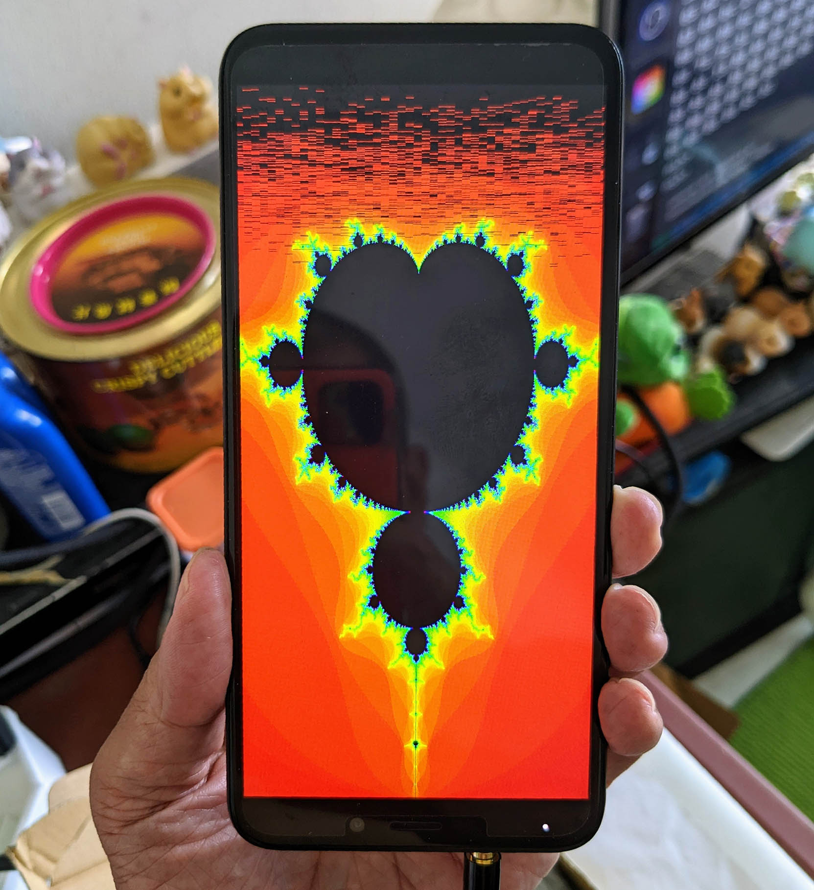
Let's look inside PinePhone's Allwinner A64 Display Engine ... And render some graphics with Apache NuttX RTOS.
Here's the doc for the Display Engine...
Which Display Engine for A64 (sun50iw1): H8, H3, H5 or A83?
PinePhone's A64 Display Engine is hidden in the Allwinner H3 Docs, because Allwinner A64 is actually a H3 upgraded with 64-bit Cores...
The A64 is basically an Allwinner H3 with the Cortex-A7 cores replaced with Cortex-A53 cores (ARM64 architecture). They share most of the memory map, clocks, interrupts and also uses the same IP blocks.
According to the doc, DE Base Address is 0x0100 0000 (Page 24)
Let's look at the DE Mixers...
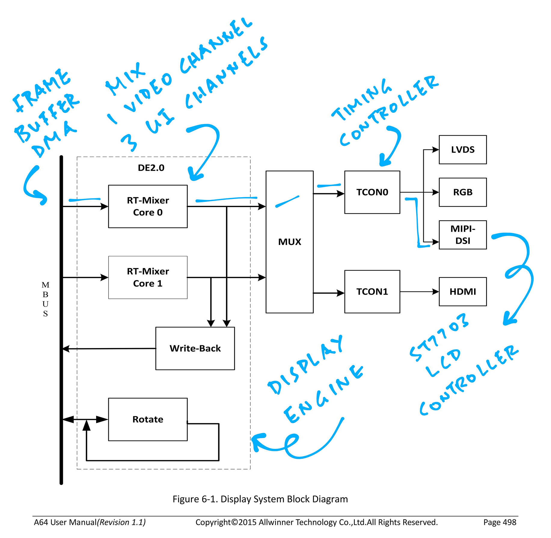
What's a Display Engine Mixer?
DE RT-MIXER: (Page 87)
The RT-mixer Core consist of dma, overlay, scaler and blender block. It supports 4 layers overlay in one pipe, and its result can scaler up or down to blender in the next processing.
The Display Engine has 2 Mixers: RT-MIXER0 and RT-MIXER1...
DE RT-MIXER0 has 4 Channels (DE Offset 0x10 0000, Page 87)
- Channel 0 for Video: DMA0, Video Overlay, Video Scaler
- Channels 1, 2, 3 for UI: DMA1 / 2 / 3, UI Overlays, UI Scalers, UI Blenders
- 4 Overlay Layers per Channel
- Layer priority is Layer 3 > Layer2 > Layer 1 > Layer 0 (Page 89)
- Channel 0 is unused (we don't use video right now)
- Channel 1 has format XRGB 8888
- Channels 2 and 3 have format ARGB 8888
- MIXER0 Registers:
- GLB at MIXER0 Offset 0x00000 (de_glb_regs)
- BLD (Blender) at MIXER0 Offset 0x01000 (de_bld_regs)
- OVL_V(CH0) (Video Overlay / Channel 0) at MIXER0 Offset 0x2000 (Unused)
- OVL_UI(CH1) (UI Overlay / Channel 1) at MIXER0 Offset 0x3000
- OVL_UI(CH2) (UI Overlay / Channel 2) at MIXER0 Offset 0x4000
- OVL_UI(CH3) (UI Overlay / Channel 3) at MIXER0 Offset 0x5000
- POST_PROC2 at MIXER0 Offset 0xB0000 (de_csc_regs)
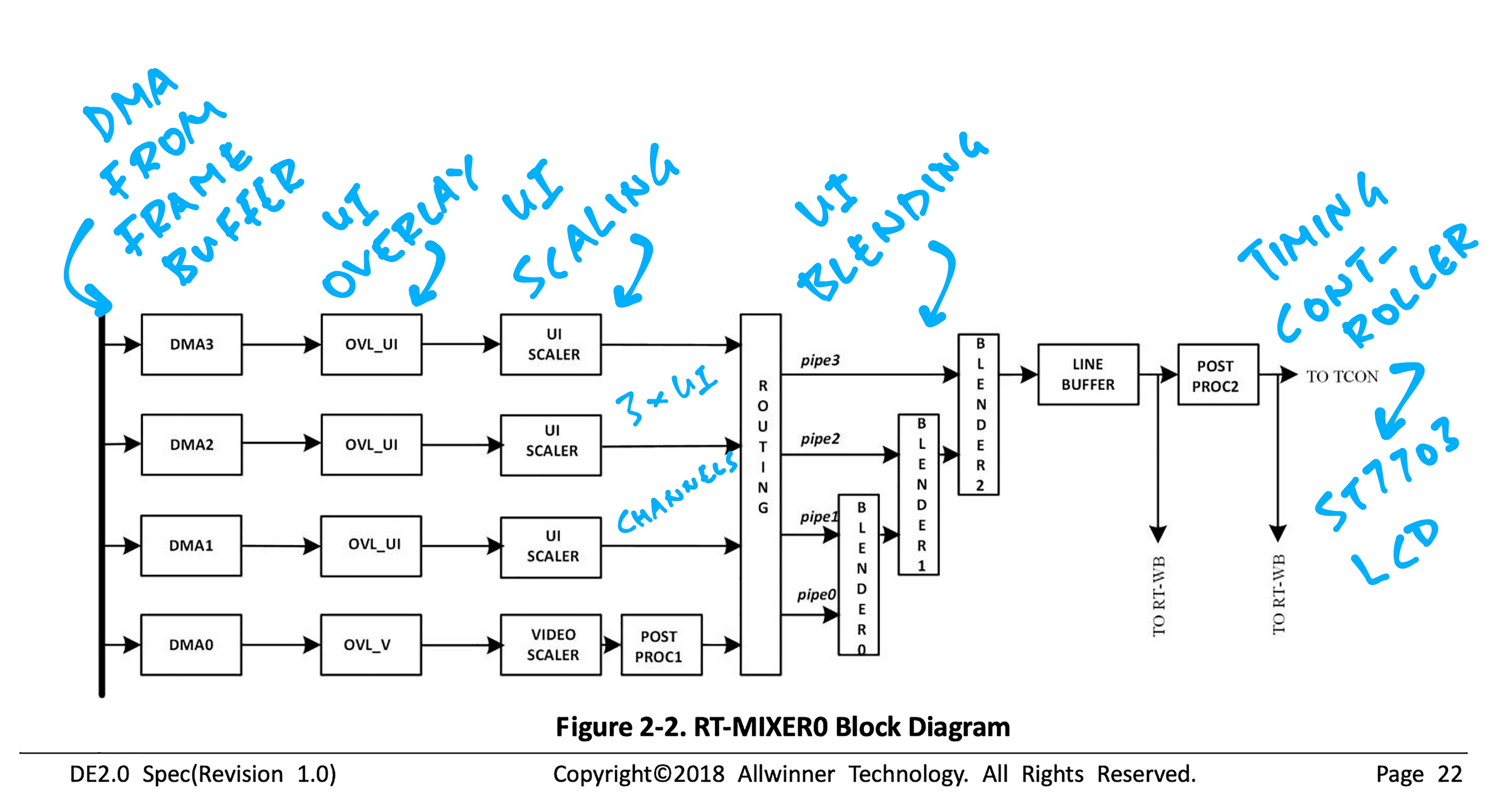
DE RT-MIXER1 has 2 Channels (DE Offset 0x20 0000, Page 23)
- Channel 0 for Video: DMA0, Video Overlay, Video Scaler
- Channel 1 for UI: DMA1, UI Overlay, UI Scaler, UI Blender
- We don't use MIXER1 right now
RT-MIXER0 and RT-MIXER1 are multiplexed to Timing Controller TCON0.
(TCON0 is connected to ST7703 over MIPI DSI)
So MIXER0 mixes 1 Video Channel with 3 UI Channels over DMA ... And pumps the pixels continuously to ST7703 LCD Controller (via the Timing Controller)
Let's use the 3 UI Channels to render: 1️⃣ Mandelbrot Set 2️⃣ Blue Square 3️⃣ Green Circle
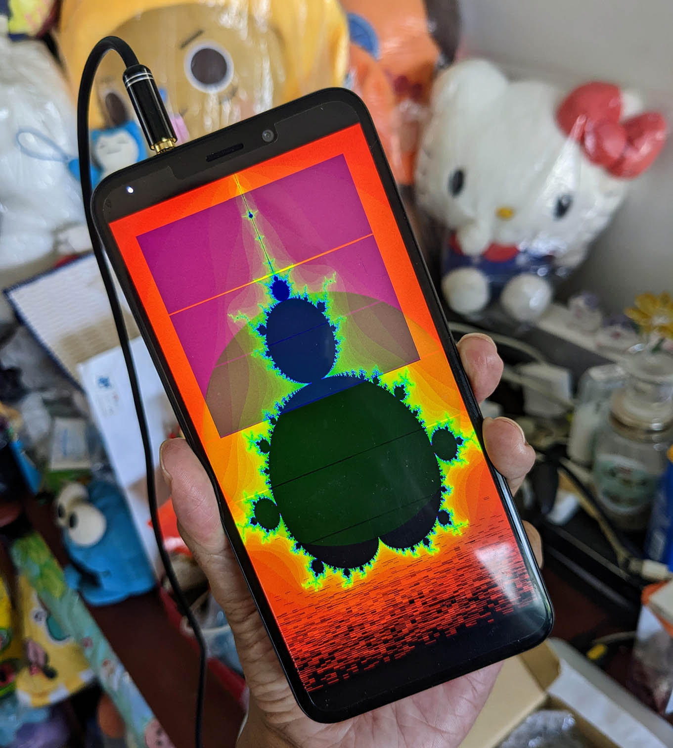
Why 2 Mixers in A64 Display Engine?
Maybe because A64 (or H3) was designed for OTT Set-Top Boxes with Picture-In-Picture Overlay Videos?
The 3 UI Overlay Channels would be useful for overlaying a Text UI on top of a Video Channel.
(Is that why Allwinner calls them "Channels"?)
(Wait... Wasn't Pine64 created thanks to OTT Boxes? 🤔)
Let's render simple colour blocks on the PinePhone Display.
We allocate the Framebuffer: test_display.c
// Init Framebuffer 0:
// Fullscreen 720 x 1440 (4 bytes per RGBA pixel)
static uint32_t fb0[720 * 1440];
int fb0_len = sizeof(fb0) / sizeof(fb0[0]);We fill the Framebuffer with Blue, Green and Red: test_display.c
// Fill with Blue, Green and Red
for (int i = 0; i < fb0_len; i++) {
// Colours are in ARGB format
if (i < fb0_len / 4) {
// Blue for top quarter
fb0[i] = 0x80000080;
} else if (i < fb0_len / 2) {
// Green for next quarter
fb0[i] = 0x80008000;
} else {
// Red for lower half
fb0[i] = 0x80800000;
}
}We allocate 3 UI Channels: test_display.c
// Allocate 3 UI Channels
static struct display disp;
memset(&disp, 0, sizeof(disp));
struct display *d = &disp;We init the 3 Channels and render them: test_display.c
// Init UI Channel 1: (Base Channel)
// Fullscreen 720 x 1440
d->planes[0].fb_start = (uintptr_t) fb0; // Framebuffer Address
d->planes[0].fb_pitch = 720 * 4; // Framebuffer Pitch
d->planes[0].src_w = 720; // Source Width
d->planes[0].src_h = 1440; // Source Height
d->planes[0].dst_w = 720; // Dest Width
d->planes[0].dst_h = 1440; // Dest Height
// Init UI Channel 2: (First Overlay)
// Square 600 x 600
d->planes[1].fb_start = 0; // To Disable Channel
// Init UI Channel 3: (Second Overlay)
// Fullscreen 720 x 1440 with Alpha Blending
d->planes[2].fb_start = 0; // To Disable Channel
// Render the UI Channels
display_commit(d);display_commit is defined in the p-boot Display Code: display.c
We should see these Blue, Green and Red Blocks...
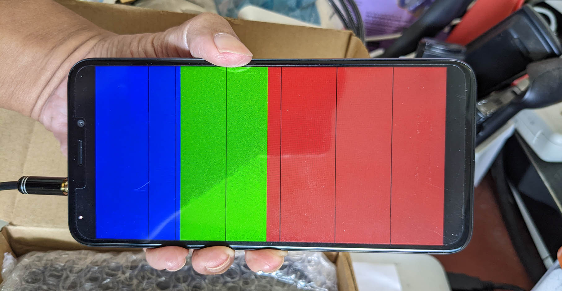
(Why the black lines?)
Channels 2 and 3 are disabled for now. We'll use them to render UI Overlays later.
Let's render something more interesting... Mandelbrot Set: test_display.c
// Fill with Mandelbrot Set
for (int y = 0; y < 1440; y++) {
for (int x = 0; x < 720; x++) {
// Convert Pixel Coordinates to a Complex Number
float cx = x_start + (y / 1440.0) * (x_end - x_start);
float cy = y_start + (x / 720.0) * (y_end - y_start);
// Compute Manelbrot Set
int m = mandelbrot(cx, cy);
// Color depends on the number of iterations
uint8_t hue = 255.0 * m / MAX_ITER;
uint8_t saturation = 255;
uint8_t value = (m < MAX_ITER) ? 255 : 0;
// Convert Hue / Saturation / Value to RGB
uint32_t rgb = hsvToRgb(hue, saturation, value);
// Set the Pixel Colour (ARGB Format)
int p = (y * 720) + x;
assert(p < fb0_len);
fb0[p] = 0x80000000 | rgb;
}
}mandelbrot and hsvToRgb are defined here: test_display.c
We should see this Mandelbrot Set...
Now we animate the Mandelbrot Set: test_display.c
// Omitted: Init UI Channels 1, 2 and 3
...
// Render the UI Channels
display_commit(d);
// Animate the Mandelbrot Set forever...
for (;;) {
// Fill with Mandelbrot Set
for (int y = 0; y < 1440; y++) {
for (int x = 0; x < 720; x++) {
// Convert Pixel Coordinates to a Complex Number
float cx = x_start + (y / 1440.0) * (x_end - x_start);
float cy = y_start + (x / 720.0) * (y_end - y_start);
// Compute Manelbrot Set
int m = mandelbrot(cx, cy);
// Color depends on the number of iterations
uint8_t hue = 255.0 * m / MAX_ITER;
uint8_t saturation = 255;
uint8_t value = (m < MAX_ITER) ? 255 : 0;
// Convert Hue / Saturation / Value to RGB
uint32_t rgb = hsvToRgb(hue, saturation, value);
// Set the Pixel Colour (ARGB Format)
int p = (y * 720) + x;
assert(p < fb0_len);
fb0[p] = 0x80000000 | rgb;
}
}
// Zoom in to (-1.4, 0)
float x_dest = -1.4;
float y_dest = 0;
x_start += (x_dest - x_start) * 0.05;
x_end -= (x_end - x_dest) * 0.05;
y_start += (y_dest - y_start) * 0.05;
y_end -= (y_end - y_dest) * 0.05;
}We should see the Animated Mandelbrot Set...
Don't we need to call display_commit after every frame?
Nope, remember that the Display Engine reads our Framebuffer directly via DMA.
So any updates to the Framebuffer will be pushed to the display instantly.
This is how we render a Blue Square as an Overlay on UI Channel 2: test_display.c
// Init Framebuffer 1:
// Square 600 x 600 (4 bytes per RGBA pixel)
static uint32_t fb1[600 * 600];
int fb1_len = sizeof(fb1) / sizeof(fb1[0]);
// Fill with Blue
for (int i = 0; i < fb1_len; i++) {
// Colours are in ARGB format
fb1[i] = 0x80000080;
}
// Init UI Channel 2: (First Overlay)
// Square 600 x 600
d->planes[1].fb_start = (uintptr_t) fb1; // Framebuffer Address
d->planes[1].fb_pitch = 600 * 4; // Framebuffer Pitch
d->planes[1].src_w = 600; // Source Width
d->planes[1].src_h = 600; // Source Height
d->planes[1].dst_w = 600; // Dest Width
d->planes[1].dst_h = 600; // Dest Height
d->planes[1].dst_x = 52; // Dest X
d->planes[1].dst_y = 52; // Dest YThis is how we render a Green Circle as an Overlay on UI Channel 3: test_display.c
// Init Framebuffer 2:
// Fullscreen 720 x 1440 (4 bytes per RGBA pixel)
static uint32_t fb2[720 * 1440];
int fb2_len = sizeof(fb2) / sizeof(fb2[0]);
// Fill with Green Circle
for (int y = 0; y < 1440; y++) {
for (int x = 0; x < 720; x++) {
// Get pixel index
int p = (y * 720) + x;
assert(p < fb2_len);
// Shift coordinates so that centre of screen is (0,0)
int x_shift = x - 360;
int y_shift = y - 720;
// If x^2 + y^2 < radius^2, set the pixel to Green
if (x_shift*x_shift + y_shift*y_shift < 360*360) {
fb2[p] = 0x80008000; // Green in ARGB Format
} else { // Otherwise set to Black
fb2[p] = 0x00000000; // Black in ARGB Format
}
}
}
// Init UI Channel 3: (Second Overlay)
// Fullscreen 720 x 1440 with Alpha Blending
d->planes[2].fb_start = (uintptr_t) fb2; // Framebuffer Address
d->planes[2].fb_pitch = 720 * 4; // Framebuffer Pitch
d->planes[2].src_w = 720; // Source Width
d->planes[2].src_h = 1440; // Source Height
d->planes[2].dst_w = 720; // Dest Width
d->planes[2].dst_h = 1440; // Dest Height
d->planes[2].dst_x = 0; // Dest X
d->planes[2].dst_y = 0; // Dest Y
d->planes[2].alpha = 128; // Dest AlphaNote that we set the Destination Alpha. So the green will appear nearly invisible.
We should see the Animated Mandelbrot Set, with Blue Square and Green Circle as Overlays...
(Why the missing horizontal lines in the Blue Square and Green Circle?)
To test the A64 Display Engine with NuttX on PinePhone, we'll run this p-boot Display Code...
With our Test App...
Here are the steps to download and run the NuttX Binary Image on PinePhone...
-
Prepare a microSD Card with PinePhone Jumpdrive...
-
Download the compressed NuttX Binary Image...
-
Copy the compressed NuttX Binary Image to Jumpdrive microSD...
## Copy compressed NuttX Binary Image to Jumpdrive microSD. ## How to create Jumpdrive microSD: https://lupyuen.github.io/articles/uboot#pinephone-jumpdrive ## TODO: Change the microSD Path cp Image.gz "/Volumes/NO NAME"
-
To access the UART Port on PinePhone, we'll connect this USB Serial Debug Cable (at 115.2 kbps)...
-
Insert the Jumpdrive microSD into PinePhone and power up
-
At the NuttX Shell, enter
hello
We should see the Animated Mandelbrot Set, with Blue Square and Green Circle as Overlays...
(Why the missing horizontal lines in the Blue Square and Green Circle?)
If we prefer to build the NuttX Binary Image ourselves, here are the steps to download the following Source Files and build them...
nuttx
├── apps (NuttX Apps for PinePhone including Display Engine Version 2)
│ ├── Application.mk
│ ├── DISCLAIMER
│ ├── Directory.mk
...
├── nuttx (NuttX OS for PinePhone)
│ ├── AUTHORS
│ ├── CONTRIBUTING.md
│ ├── DISCLAIMER
...
├── p-boot (Modified p-boot Display Code)
│ ├── HACKING
│ ├── LICENSE
│ ├── NEWS
...
└── pinephone-nuttx (Zig MIPI DSI Driver for PinePhone)
├── LICENSE
├── README.md
├── display.o
└── display.zig
-
Create the NuttX Directory...
mkdir nuttx cd nuttx -
Download the Modified Instrumented p-boot Display Code
p-boot.6.zipfrom...pinephone-nuttx/releases/tag/pboot6
Extract into the
nuttxfolder and rename asp-boot -
Download and build NuttX for PinePhone inside the
nuttxfolder...## TODO: Install Build Prerequisites ## https://lupyuen.github.io/articles/uboot#install-prerequisites ## Download NuttX OS for PinePhone git clone \ --recursive \ --branch pinephone \ https://github.com/lupyuen/incubator-nuttx \ nuttx ## Download NuttX Apps for PinePhone including Display Engine (Version 2) git clone \ --recursive \ --branch de2 \ https://github.com/lupyuen/incubator-nuttx-apps \ apps ## We'll build NuttX inside nuttx/nuttx cd nuttx ## Configure NuttX for Single Core ./tools/configure.sh -l qemu-a53:nsh ## Build NuttX. Ignore the Linker Errors make
-
Follow these steps to compile our Zig MIPI DSI Driver and link into NuttX...
-
Compress the NuttX Binary Image...
cp nuttx.bin Image rm -f Image.gz gzip Image
-
Copy the compressed NuttX Binary Image
Image.gzto Jumpdrive microSD according to the steps above.Insert the Jumpdrive microSD into PinePhone and power up.
At the NuttX Shell, enter
hello
(The steps look messy today, hopefully we'll remove p-boot after we have created our NuttX Display Driver)
Based on the log captured from our instrumented test_display.c, we have identified the steps to render 3 UI Channels (1 to 3) with the Display Engine (display_commit)
This is how we'll create a NuttX Driver for PinePhone's A64 Display Engine that implements Display Rendering...
-
Configure Blender...
- BLD BkColor (BLD_BK_COLOR Offset 0x88): BLD background color register
- BLD Premultiply (BLD_PREMUL_CTL Offset 0x84): BLD pre-multiply control register
Configure Blender BLD BkColor: 0x110 1088 = 0xff000000 BLD Premultiply: 0x110 1084 = 0x0 -
For Channels 1 to 3...
-
If Channel is unused, disable Overlay, Pipe and Scaler. Skip to next Channel
- UI Config Attr (OVL_UI_ATTCTL @ OVL_UI Offset 0x00): OVL_UI attribute control register
- Mixer (??? @ 0x113 0000 + 0x10000 * Channel)
Channel 2: Disable Overlay and Pipe UI Config Attr: 0x110 4000 = 0x0 Channel 3: Disable Overlay and Pipe UI Config Attr: 0x110 5000 = 0x0 Channel 2: Disable Scaler Mixer: 0x115 0000 = 0x0 Channel 3: Disable Scaler Mixer: 0x116 0000 = 0x0 -
Channel 1 has format XRGB 8888, Channel 2 and 3 have format ARGB 8888
-
Set Overlay (Assume Layer = 0)
- UI Config Attr (OVL_UI_ATTCTL @ OVL_UI Offset 0x00): OVL_UI attribute control register
- UI Config Top LAddr (OVL_UI_TOP_LADD @ OVL_UI Offset 0x10): OVL_UI top field memory block low address register
- UI Config Pitch (OVL_UI_PITCH @ OVL_UI Offset 0x0C): OVL_UI memory pitch register
- UI Config Size (OVL_UI_MBSIZE @ OVL_UI Offset 0x04): OVL_UI memory block size register
- UI Overlay Size (OVL_UI_SIZE @ OVL_UI Offset 0x88): OVL_UI overlay window size register
- IO Config Coord (OVL_UI_COOR @ OVL_UI Offset 0x08): OVL_UI memory block coordinate register
Channel 1: Set Overlay (fb0 is 720 x 1440) UI Config Attr: 0x110 3000 = 0xff00 0405 UI Config Top LAddr: 0x110 3010 = 0x4064 a6ac (Address of fb0) UI Config Pitch: 0x110 300c = 0xb40 (720 * 4) UI Config Size: 0x110 3004 = 0x59f 02cf (1439 << 16 + 719) UI Overlay Size: 0x110 3088 = 0x59f 02cf (1439 << 16 + 719) IO Config Coord: 0x110 3008 = 0x0 Channel 2: Set Overlay (fb1 is 600 x 600) UI Config Attr: 0x110 4000 = 0xff00 0005 UI Config Top LAddr: 0x110 4010 = 0x404e adac (Address of fb1) UI Config Pitch: 0x110 400c = 0x960 (600 * 4) UI Config Size: 0x110 4004 = 0x257 0257 (599 << 16 + 599) UI Overlay Size: 0x110 4088 = 0x257 0257 (599 << 16 + 599) IO Config Coord: 0x110 4008 = 0x0 Channel 3: Set Overlay (fb2 is 720 x 1440) UI Config Attr: 0x110 5000 = 0x7f00 0005 UI Config Top LAddr: 0x110 5010 = 0x400f 65ac (Address of fb2) UI Config Pitch: 0x110 500c = 0xb40 (720 * 4) UI Config Size: 0x110 5004 = 0x59f 02cf (1439 << 16 + 719) UI Overlay Size: 0x110 5088 = 0x59f 02cf (1439 << 16 + 719) IO Config Coord: 0x110 5008 = 0x0Note that UI Config Size and UI Overlay Size are
(height-1) << 16 + (width-1) -
For Channel 1: Set Blender Output
- BLD Output Size (BLD_SIZE @ BLD Offset 0x08C): BLD output size setting register
- GLB Size (GLB_SIZE @ GLB Offset 0x00C): Global size register
Channel 1: Set Blender Output BLD Output Size: 0x110 108c = 0x59f 02cf (1439 * 16 + 719) GLB Size: 0x110 000c = 0x59f 02cf (1439 * 16 + 719) -
Set Blender Input Pipe (N = Pipe Number, from 0 to 2 for Channels 1 to 3)
- BLD Pipe InSize (BLD_CH_ISIZE @ BLD Offset 0x008 + N*0x14): BLD input memory size register(N=0,1,2,3,4)
- BLD Pipe FColor (BLD_FILL_COLOR @ BLD Offset 0x004 + N*0x14): BLD fill color register(N=0,1,2,3,4)
- BLD Pipe Offset (BLD_CH_OFFSET @ BLD Offset 0x00C + N*0x14): BLD input memory offset register(N=0,1,2,3,4)
- BLD Pipe Mode (BLD_CTL @ BLD Offset 0x090 – 0x09C): BLD control register
(Should
N*0x14beN*0x10instead?)Channel 1: Set Blender Input Pipe 0 (fb0 is 720 x 1440) BLD Pipe InSize: 0x110 1008 = 0x59f 02cf (1439 * 16 + 719) BLD Pipe FColor: 0x110 1004 = 0xff00 0000 BLD Pipe Offset: 0x110 100c = 0x0 BLD Pipe Mode: 0x110 1090 = 0x301 0301 Channel 2: Set Blender Input Pipe 1 (fb1 is 600 x 600) BLD Pipe InSize: 0x110 1018 = 0x257 0257 (599 << 16 + 599) BLD Pipe FColor: 0x110 1014 = 0xff00 0000 BLD Pipe Offset: 0x110 101c = 0x34 0034 BLD Pipe Mode: 0x110 1094 = 0x301 0301 Channel 3: Set Blender Input Pipe 2 (fb2 is 720 x 1440) BLD Pipe InSize: 0x110 1028 = 0x59f 02cf (1439 * 16 + 719) BLD Pipe FColor: 0x110 1024 = 0xff00 0000 BLD Pipe Offset: 0x110 102c = 0x0 BLD Pipe Mode: 0x110 1098 = 0x301 0301Note that BLD Pipe InSize is
(height-1) << 16 + (width-1) -
Disable Scaler (assuming we're not using Scaler)
Channel 1: Disable Scaler Mixer: 0x114 0000 = 0x0 Channel 2: Disable Scaler Mixer: 0x115 0000 = 0x0 Channel 3: Disable Scaler Mixer: 0x116 0000 = 0x0
-
-
Set BLD Route and BLD FColor Control
- BLD Route (BLD_CH_RTCTL @ BLD Offset 0x080): BLD routing control register
- BLD FColor Control (BLD_FILLCOLOR_CTL @ BLD Offset 0x000): BLD fill color control register
Set BLD Route and BLD FColor Control BLD Route: 0x110 1080 = 0x321 BLD FColor Control: 0x110 1000 = 0x701 -
Apply Settings: GLB DBuff
- GLB DBuff (GLB_DBUFFER @ GLB Offset 0x008): Global double buffer control register
Apply Settings GLB DBuff: 0x110 0008 = 0x1
(See Memory Mapping List and Register List at Page 90)
We won't use these Display Engine Features today...
DE RT-WB: (Page 116)
The Real-time write-back controller (RT-WB) provides data capture function for display engine. It captures data from RT-mixer module, performs the image resizing function, and then write-back to SDRAM.
(For screen capture?)
DE VSU: (Page 128)
The Video Scaler (VS) provides YUV format image resizing function for display engine. It receives data from overlay module, performs the image resizing function, and outputs to video post-processing modules.
DE Rotation: (Page 137)
There are several types of rotation: clockwise 0/90/180/270 degree Rotation and H-Flip/V-Flip. Operation of Copy is the same as a 0 degree rotation.
See this...
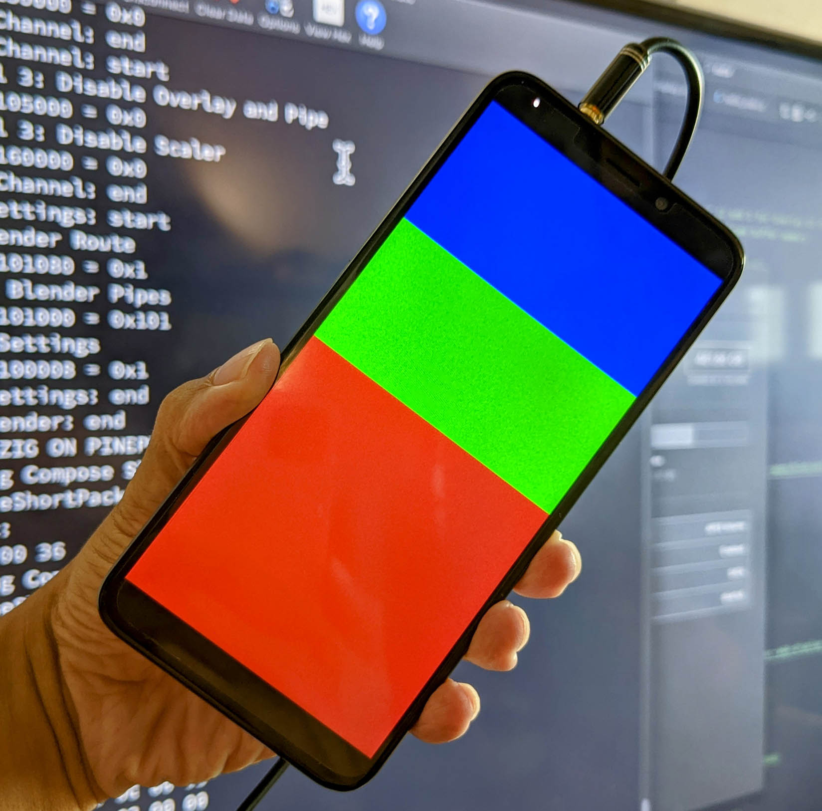
We have created a Zig Driver for PinePhone's Allwinner A64 Display Engine that will render graphics...
To test the rendering of graphics, let's run this Zig App on NuttX for PinePhone...
Follow the instructions in the next section to download and build the NuttX Source Code for PinePhone.
In NuttX, enable the Null Example App: make menuconfig, select "Application Configuration" > "Examples" > "Null Example"
Compile the Zig App (based on the GCC Compiler Options, see below)...
# Change "$HOME/nuttx" for your NuttX Project Directory
cd $HOME/nuttx
# Download the Zig App
git clone --recursive https://github.com/lupyuen/pinephone-nuttx
cd pinephone-nuttx
# Compile the Zig App for PinePhone
# (armv8-a with cortex-a53)
# TODO: Change "$HOME/nuttx" to your NuttX Project Directory
zig build-obj \
--verbose-cimport \
-target aarch64-freestanding-none \
-mcpu cortex_a53 \
-isystem "$HOME/nuttx/nuttx/include" \
-I "$HOME/nuttx/apps/include" \
render.zig
# Copy the compiled app to NuttX and overwrite `null.o`
# TODO: Change "$HOME/nuttx" to your NuttX Project Directory
cp render.o \
$HOME/nuttx/apps/examples/null/*null.o
# Build NuttX to link the Zig Object from `null.o`
# TODO: Change "$HOME/nuttx" to your NuttX Project Directory
cd $HOME/nuttx/nuttx
makeTo run the Zig App...
## Render colour bars (pic above)
hello 1
## Render colour bars with overlays (pic below)
hello 3
How did we get the Zig Compiler options -target, -mcpu, -isystem and -I?
make --trace shows these GCC Compiler Options when building Nuttx for PinePhone...
aarch64-none-elf-gcc
-c
-fno-common
-Wall
-Wstrict-prototypes
-Wshadow
-Wundef
-Werror
-Os
-fno-strict-aliasing
-fomit-frame-pointer
-g
-march=armv8-a
-mtune=cortex-a53
-isystem "/Users/Luppy/PinePhone/nuttx/nuttx/include"
-D__NuttX__
-pipe
-I "/Users/Luppy/PinePhone/nuttx/apps/include"
-Dmain=hello_main hello_main.c
-o hello_main.c.Users.Luppy.PinePhone.nuttx.apps.examples.hello.oWe copied and modified these GCC Compiler Options for Zig.
What about -D__NuttX__?
The Zig Compiler won't let us specify C Macros at the Command Line, so we defined the macro __NuttX__ in our Zig App...
Lines 32 to 53 in 6ba90ed

To test the A64 Display Engine with NuttX on PinePhone, we'll run our NuttX Test App...
Which calls our Zig Display Driver for PinePhone...
Here are the steps to download and run the NuttX Binary Image on PinePhone...
-
Prepare a microSD Card with PinePhone Jumpdrive...
-
Download the compressed NuttX Binary Image...
-
Copy the compressed NuttX Binary Image to Jumpdrive microSD...
## Copy compressed NuttX Binary Image to Jumpdrive microSD. ## How to create Jumpdrive microSD: https://lupyuen.github.io/articles/uboot#pinephone-jumpdrive ## TODO: Change the microSD Path cp Image.gz "/Volumes/NO NAME"
-
To access the UART Port on PinePhone, we'll connect this USB Serial Debug Cable (at 115.2 kbps)...
-
Insert the Jumpdrive microSD into PinePhone and power up
-
At the NuttX Shell, enter
hello 1to render the Blue, Green and Red colour bars -
Or enter
hello 3to render the same colour bars with Blue Square and Green Circle as Overlays
If we prefer to build the NuttX Binary Image ourselves, here are the steps to download the following Source Files and build them...
nuttx
├── apps (NuttX Apps for PinePhone including Display Engine Version 2)
│ ├── Application.mk
│ ├── DISCLAIMER
│ ├── Directory.mk
...
├── nuttx (NuttX OS for PinePhone)
│ ├── AUTHORS
│ ├── CONTRIBUTING.md
│ ├── DISCLAIMER
...
├── p-boot (Modified p-boot Display Code)
│ ├── HACKING
│ ├── LICENSE
│ ├── NEWS
...
└── pinephone-nuttx (Zig MIPI DSI / Display Engine Driver for PinePhone)
├── LICENSE
├── README.md
├── display.zig
└── render.zig
-
Create the NuttX Directory...
mkdir nuttx cd nuttx -
Download the Modified p-boot Display Code
p-boot.11.zipfrom...pinephone-nuttx/releases/tag/pboot11
Extract into the
nuttxfolder and rename asp-boot -
Download and build NuttX for PinePhone inside the
nuttxfolder...## TODO: Install Build Prerequisites ## https://lupyuen.github.io/articles/uboot#install-prerequisites ## Download NuttX OS for PinePhone git clone \ --recursive \ --branch pinephone \ https://github.com/lupyuen/incubator-nuttx \ nuttx ## Download NuttX Apps for PinePhone including Display Engine (Version 3) git clone \ --recursive \ --branch de3 \ https://github.com/lupyuen/incubator-nuttx-apps \ apps ## We'll build NuttX inside nuttx/nuttx cd nuttx ## Configure NuttX for Single Core ./tools/configure.sh -l qemu-a53:nsh ## Build NuttX. Ignore the Linker Errors make
-
Follow these steps to compile our Zig MIPI DSI Driver and link into NuttX...
-
Compress the NuttX Binary Image...
cp nuttx.bin Image rm -f Image.gz gzip Image
-
Copy the compressed NuttX Binary Image
Image.gzto Jumpdrive microSD according to the steps above.Insert the Jumpdrive microSD into PinePhone and power up.
At the NuttX Shell, enter
hello 1orhello 3
(The steps look messy today, hopefully we'll remove p-boot after we have created our NuttX Display Driver)
We have completed the entire PinePhone Display Driver in Zig!
Lines 176 to 226 in 432c15a
Here are the Zig Modules...
-
render.zig: Allwinner A64 Display Engine (DE) -
display.zig: Allwinner A64 MIPI Display Serial Interface (DSI) -
dphy.zig: Allwinner A64 MIPI Display Physical Layer (DPHY) -
tcon.zig: Allwinner A64 Timing Controller (TCON0) -
backlight.zig: PinePhone Display Backlight -
pmic.zig: PinePhone Power Management Integrated Circuit -
panel.zig: PinePhone LCD Panel
This is the detailed output of the Zig Driver, with Register Addresses and Values...
We'll merge these modules to NuttX Mainline as a NuttX Framebuffer Driver.
We created these modules by reverse-engineering the log generated by the p-boot Display Code.
We're adding the MIPI DSI Driver to the NuttX Kernel...
-
mipi_dsi.c: Compose MIPI DSI Packets (Long, Short, Short with Parameter)
-
a64_mipi_dsi.c: MIPI Display Serial Interface (DSI) for Allwinner A64
-
a64_mipi_dphy.c: MIPI Display Physical Layer (D-PHY) for Allwinner A64
We created the above NuttX Source Files (in C) by converting our Zig MIPI DSI Driver to C...
-
display.zig: Zig Driver for MIPI DSI
-
dphy.zig: Zig Driver for MIPI D-PHY
That we Reverse-Engineered from the logs that we captured from PinePhone p-boot...
Was it difficult to convert Zig to C?
Not at all!
Here's the Zig code for our MIPI DSI Driver...
Lines 115 to 170 in 3d33e5a
And here's the converted C code for NuttX: mipi_dsi.c
ssize_t mipi_dsi_short_packet(FAR uint8_t *pktbuf,
size_t pktlen,
uint8_t channel,
enum mipi_dsi_e cmd,
FAR const uint8_t *txbuf,
size_t txlen)
{
/* Data Identifier (DI) (1 byte):
* Virtual Channel Identifier (Bits 6 to 7)
* Data Type (Bits 0 to 5) */
const uint8_t vc = channel;
const uint8_t dt = cmd;
const uint8_t di = (vc << 6) |
dt;
/* Data (2 bytes): Fill with 0 if Second Byte is missing */
const uint8_t data[2] =
{
txbuf[0], /* First Byte */
(txlen == 2) ? txbuf[1] : 0, /* Second Byte */
};
/* Data Identifier + Data (3 bytes):
* For computing Error Correction Code (ECC) */
const uint8_t di_data[3] =
{
di,
data[0],
data[1]
};
/* Compute ECC for Data Identifier + Word Count */
const uint8_t ecc = compute_ecc(di_data,
sizeof(di_data));
/* Packet Header (4 bytes):
* Data Identifier + Data + Error Correction Code */
const uint8_t header[4] =
{
di_data[0],
di_data[1],
di_data[2],
ecc
};
/* Packet Length is Packet Header Size (4 bytes) */
const size_t len = sizeof(header);
ginfo("channel=%d, cmd=0x%x, txlen=%ld\n", channel, cmd, txlen);
DEBUGASSERT(pktbuf != NULL && txbuf != NULL);
DEBUGASSERT(channel < 4);
DEBUGASSERT(cmd < (1 << 6));
if (txlen < 1 || txlen > 2) { DEBUGPANIC(); return ERROR; }
if (len > pktlen) { DEBUGPANIC(); return ERROR; }
/* Copy Packet Header to Packet Buffer */
memcpy(pktbuf,
header,
sizeof(header)); /* 4 bytes */
/* Return the Packet Length */
return len;
}The code looks highly similar!
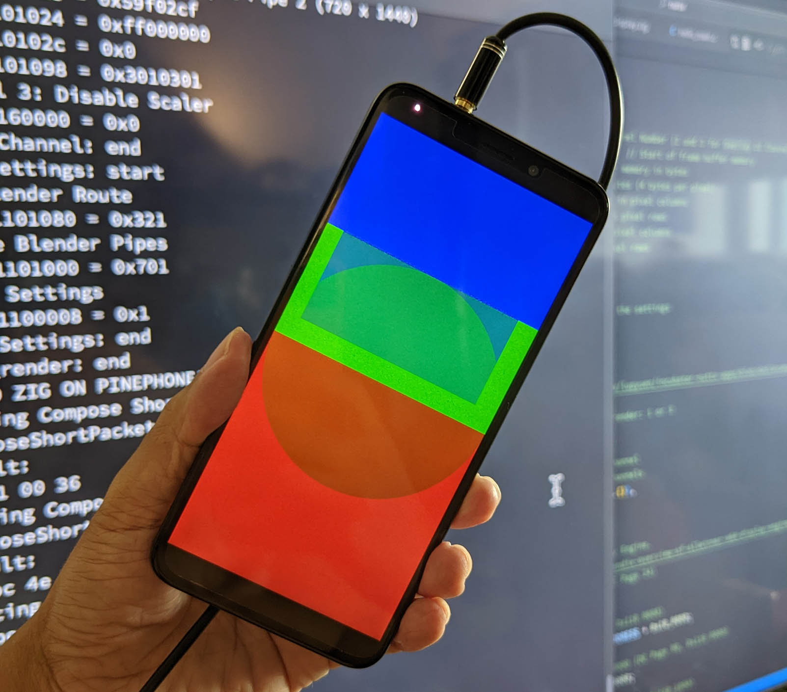
How do we test the MIPI DSI Driver in the NuttX Kernel?
Right now we have implemented the following in the NuttX Kernel...
- Driver for MIPI Display Serial Interface (DSI)
- Driver for MIPI Display Physical Layer (D-PHY)
But to render graphics on PinePhone we need the following drivers, which are still in Zig, pending conversion to C...
- Driver for Display Backlight
- Driver for Timing Controller TCON0
- Driver for Power Mgmt IC
- Driver for LCD Panel
- Driver for Display Engine
Running an Integration Test across the C and Zig Drivers will be a little interesting. Here's how we run the Integration Test...
We created this program in Zig that calls the C and Zig Drivers, in the right sequence...
Lines 1143 to 1176 in bc560ce
Then we compile the Zig Test Program targeting PinePhone...
## Configure NuttX
cd nuttx
./tools/configure.sh pinephone:nsh
make menuconfig
## Select "System Type > Allwinner A64 Peripheral Selection > DE"
## Select "System Type > Allwinner A64 Peripheral Selection > RSB"
## Select "Build Setup > Debug Options > Graphics Debug Features > Error + Warnings + Info"
## Select "Build Setup > Debug Options > Battery-related Debug Features > Error + Warnings + Info"
## Select "Device Drivers > Framebuffer Overlay Support"
## Save and exit menuconfig
## Build NuttX
make
## Download the Zig Test Program
pushd $HOME
git clone https://github.com/lupyuen/pinephone-nuttx
cd pinephone-nuttx
## Compile the Zig App for PinePhone
## (armv8-a with cortex-a53)
## TODO: Change "$HOME/nuttx" to your NuttX Project Directory
zig build-obj \
--verbose-cimport \
-target aarch64-freestanding-none \
-mcpu cortex_a53 \
-isystem "$HOME/nuttx/nuttx/include" \
-I "$HOME/nuttx/apps/include" \
render.zig
## Copy the compiled app to NuttX and overwrite `hello.o`
## TODO: Change "$HOME/nuttx" to your NuttX Project Directory
cp render.o \
$HOME/nuttx/apps/examples/hello/*hello.o
## Return to the NuttX Folder
popd
## Link the Compiled Zig App with NuttX
make(Or download the binaries here)
We boot NuttX on PinePhone and run the Zig Test Program...
NuttShell (NSH) NuttX-11.0.0-pinephone
nsh> uname -a
NuttX 11.0.0-pinephone 2a1577a-dirty Dec 9 2022 13:57:47 arm64 pinephone
nsh> hello 0
Yep our Zig Test Program renders graphics successfully on PinePhone! (Pic above)
Which means the NuttX Kernel Drivers for MIPI DSI are working OK!
Here's the Test Log for our Zig Test Program running on NuttX and PinePhone...
What about Unit Testing? Can we test the MIPI DSI / D-PHY Driver without other drivers?
Yep! Our MIPI DSI Driver simply writes values to a bunch of A64 Hardware Registers, like so: a64_mipi_dsi.c
/* DSI Configuration Register 1 (A31 Page 846)
* Set Video_Start_Delay (Bits 4 to 16) to 1468 (Line Delay)
* Set Video_Precision_Mode_Align (Bit 2) to 1 (Fill Mode)
* Set Video_Frame_Start (Bit 1) to 1 (Precision Mode)
* Set DSI_Mode (Bit 0) to 1 (Video Mode)
* Note: Video_Start_Delay is actually 13 bits, not 8 bits as stated
* in A31 User Manual
*/
#define DSI_BASIC_CTL1_REG (A64_DSI_ADDR + 0x14)
#define DSI_MODE (1 << 0)
#define VIDEO_FRAME_START (1 << 1)
#define VIDEO_PRECISION_MODE_ALIGN (1 << 2)
#define VIDEO_START_DELAY(n) (n << 4)
dsi_basic_ctl1 = VIDEO_START_DELAY(1468) |
VIDEO_PRECISION_MODE_ALIGN |
VIDEO_FRAME_START |
DSI_MODE;
putreg32(dsi_basic_ctl1, DSI_BASIC_CTL1_REG);
// Include Test Code
#include "../../pinephone-nuttx/test/test_a64_mipi_dsi2.c"So we only need to ensure that the Hardware Addresses and the Written Values are correct.
To do that, we use Assertion Checks to verify the Addresses and Values: test_a64_mipi_dsi2.c
// Test Code
DEBUGASSERT(DSI_BASIC_CTL1_REG == 0x1ca0014);
DEBUGASSERT(dsi_basic_ctl1 == 0x5bc7);If the Addresses or Values are incorrect, our MIPI DSI Driver halts with an Assertion Failure.
(We remove the Assertion Checks in the final version of our driver)
What about a smaller, self-contained Unit Test for MIPI DSI?
Here's the Unit Test that verifies MIPI DSI Packets (Long / Short / Short with Parameter) are composed correctly...
pinephone-nuttx/test/test_mipi_dsi.c
Lines 1 to 109 in 46f055e
Can we test the MIPI DSI Driver on our Local Computer? Without running on PinePhone?
Most certainly! In fact we test the MIPI DSI Driver on our Local Computer first before testing on PinePhone. Here's how...
Remember that our MIPI DSI Driver simply writes values to a bunch of A64 Hardware Registers. So we only need to ensure that the Hardware Addresses and the Written Values are correct.
We created a Test Scaffold that simulates the NuttX Build Environment...
Lines 7 to 51 in 44167d8
Then we compile the Test Scaffold and run it on our Local Computer...
Lines 9 to 36 in cdb6bbc
Note that we capture the Actual Test Log and we diff it with the Expected Test Log. That's how we detect discrepancies in the Hardware Addresses and the Written Values...
Lines 4 to 20 in c04f144
We're adding the Timing Controller TCON0 Driver to NuttX Kernel...
Right now we have implemented the following in the NuttX Kernel...
- Driver for MIPI Display Serial Interface (DSI)
- Driver for MIPI Display Physical Layer (D-PHY)
- Driver for Timing Controller TCON0
But to render graphics on PinePhone we need the following drivers, which are still in Zig, pending conversion to C...
- Driver for Display Backlight
- Driver for Power Mgmt IC
- Driver for LCD Panel
- Driver for Display Engine
So we created this Test Program in Zig that calls the C and Zig Drivers, in the right sequence...
Lines 1146 to 1199 in 15111a2
We boot NuttX on PinePhone and run the Zig Test Program...
NuttShell (NSH) NuttX-11.0.0-pinephone
nsh> uname -a
NuttX 11.0.0-pinephone 893b147 Dec 14 2022 23:01:27 arm64 pinephone
nsh> hello 0
Our Zig Test Program renders the Test Pattern successfully on PinePhone. (Like this)
Here's the Test Log, with Graphics Logging Enabled...
We also tested with Graphics Logging Disabled, to preempt any timing issues...
We're adding the Display Engine Driver to NuttX Kernel...
Right now we have implemented the following in the NuttX Kernel...
- Driver for MIPI Display Serial Interface (DSI)
- Driver for MIPI Display Physical Layer (D-PHY)
- Driver for Timing Controller TCON0
- Driver for Display Engine
But to render graphics on PinePhone we need the following drivers, which are still in Zig, pending conversion to C...
- Driver for Display Backlight
- Driver for Power Mgmt IC
- Driver for LCD Panel
- Driver for Pulse-Width Modulation
- Driver for Reduced Serial Bus
So we created this Test Program in Zig that calls the C and Zig Drivers, in the right sequence...
Lines 1146 to 1194 in 720b804
We boot NuttX on PinePhone and run the Zig Test Program...
NuttShell (NSH) NuttX-11.0.0-pinephone
nsh> uname -a
NuttX 11.0.0-pinephone 7d85079-dirty Dec 17 2022 11:43:03 arm64 pinephone
nsh> hello 0
Our Zig Test Program renders the Test Pattern successfully on PinePhone. (Like this)
Here's the Test Log, with Graphics Logging Enabled...
We also tested with Graphics Logging Disabled, to preempt any timing issues...
We've just implemented the NuttX Kernel Drivers for MIPI Display Serial Interface, Timing Controller TCON0, Display Engine, Reduced Serial Bus, Power Management Integrated Circuit and LCD Panel...
And we're adding the Framebuffer Driver to NuttX Kernel...
When we run the fb NuttX Example App, we see missing pixels in the rendered image...
-
Inside the Yellow Box is supposed to be an Orange Box
-
Inside the Orange Box is supposed to be a Red Box
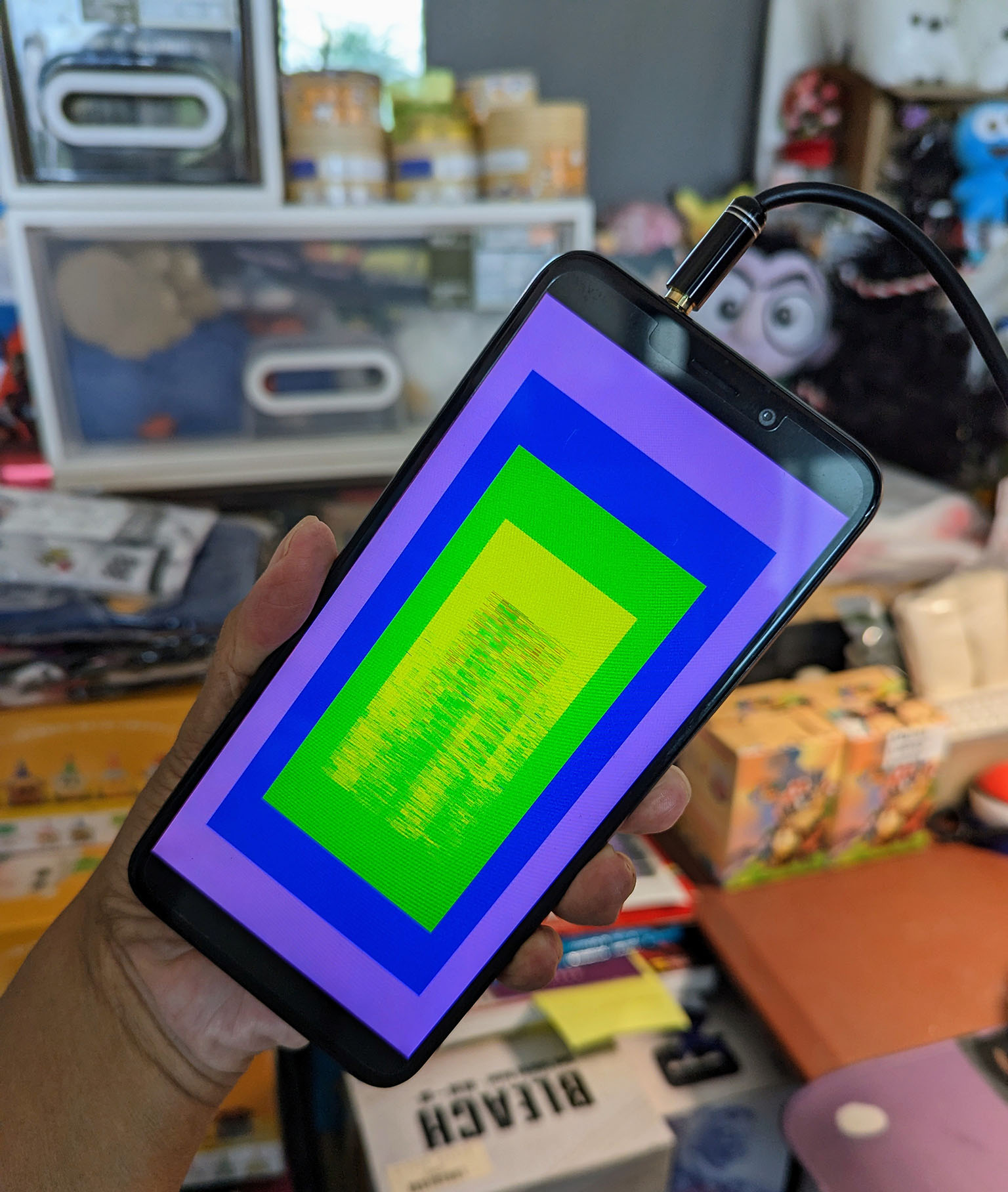
The missing pixels magically appear later in a curious pattern...
There seems to be a problem with Framebuffer DMA / Display Engine / Timing Controller TCON0?
According to the video, the pixels are actually written correctly to the RAM Framebuffer. But the pixels at the lower half don't get pushed to the display until the next screen refresh.
There seems to be a lag between the writing of pixels to framebuffer, and the pushing of pixels to the display over DMA / Display Engine / Timing Controller TCON0.
Here's the fix for this lag...
In the previous section we saw that there was a lag pushing pixels from the RAM Framebuffer to the PinePhone Display (over DMA / Display Engine / Timing Controller TCON0).
Can we overcome this lag by copying the RAM Framebuffer to itself, forcing the display to refresh? This sounds very strange, but yes it works!
From pinephone_display.c:
// Update the display when there is a change to the framebuffer.
// (ioctl Entrypoint: FBIO_UPDATE)
static int pinephone_updatearea(
struct fb_vtable_s *vtable, // Framebuffer driver object
const struct fb_area_s *area // Updated area of framebuffer
) {
uint8_t *fb = (uint8_t *)g_pinephone_fb0;
const size_t fbsize = sizeof(g_pinephone_fb0);
// Copy the entire framebuffer to itself,
// to fix the missing pixels.
// Not sure why this works.
for (int i = 0; i < fbsize; i++) {
// Declare as volatile to prevent compiler optimization
volatile uint8_t v = fb[i];
fb[i] = v;
}
return OK;
}With the code above, the Red, Orange and Yellow Boxes are now rendered correctly in our NuttX Framebuffer Driver for PinePhone. (Pic below)
Who calls pinephone_updatearea?
After writing the pixels to the RAM Framebuffer, NuttX Apps will call ioctl(FBIO_UPDATE) to update the display.
This triggers pinephone_updatearea in our NuttX Framebuffer Driver: fb_main.c
// Omitted: NuttX App writes pixels to RAM Framebuffer
// Update the Framebuffer
#ifdef CONFIG_FB_UPDATE
ret = ioctl( // I/O Command
state->fd, // Framebuffer File Descriptor
FBIO_UPDATE, // Update the Framebuffer
(unsigned long)((uintptr_t)area) // Updated area
);
#endif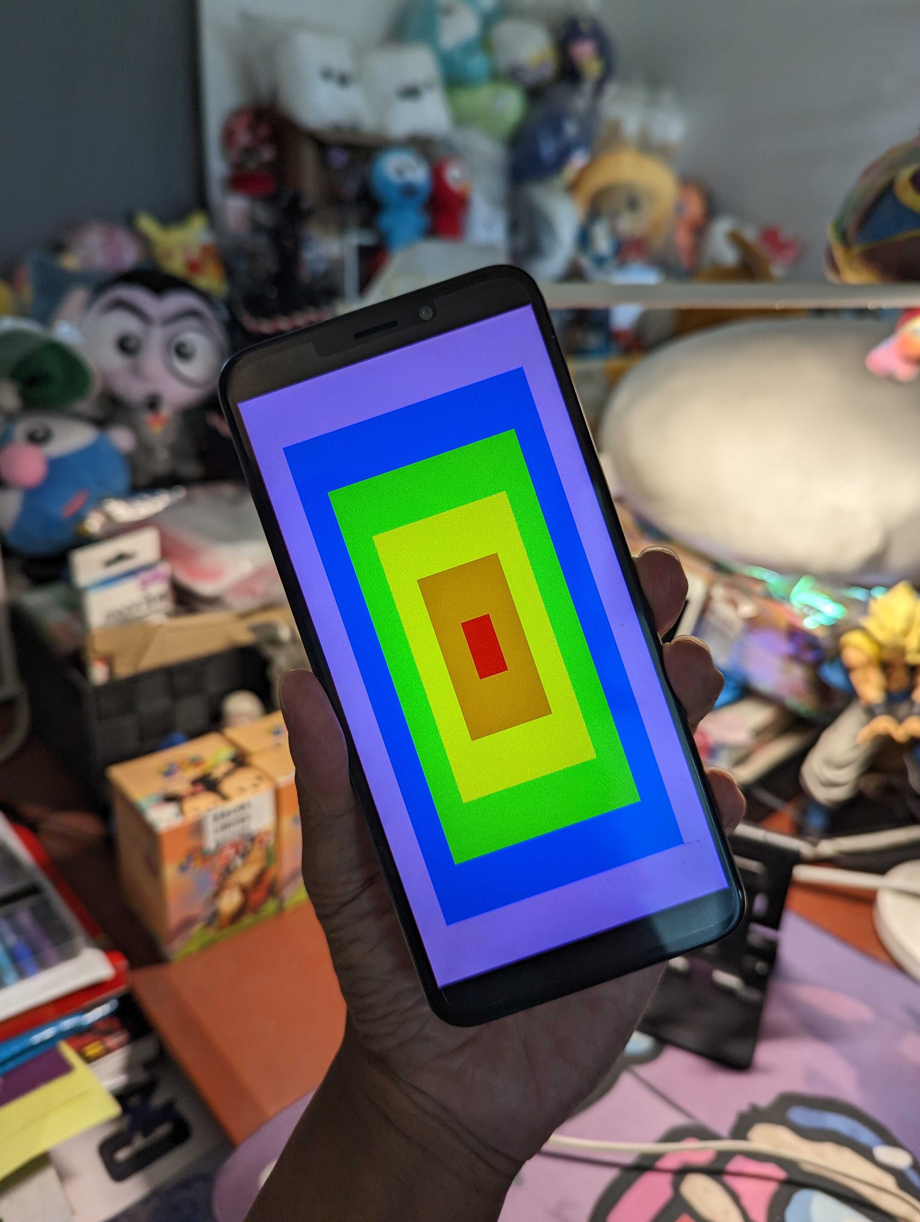
How do other PinePhone operating systems handle this?
We might need to handle TCON0 Vertical Blanking (TCON0_Vb_Int_En / TCON0_Vb_Int_Flag) and TCON0 CPU Trigger Mode Finish (TCON0_Tri_Finish_Int_En / TCON0_Tri_Finish_Int_Flag) like this...
p-boot Bootloader seems to handle every TCON0 CPU Trigger Mode Finish (TCON0_Tri_Finish_Int_En / TCON0_Tri_Finish_Int_Flag) by updating the Display Engine Registers. Which sounds odd...
-
Render Loop waits forever for
EV_VBLANK: dtest.c -
EV_VBLANKis triggered bydisplay_frame_done: gui.c -
display_frame_doneis triggered by TCON0 CPU Trigger Mode Finish: display.c -
Render Loop handles
EV_VBLANKby redrawing and callingdisplay_commit: dtest.c -
display_commitupdates the Display Engine Registers, including the Framebuffer Addresses: display.c
Can we handle TCON0 CPU Trigger Mode Finish without refreshing the Display Engine Registers?
Read the article...
We're merging PinePhone into NuttX Mainline!
NuttX Mainline now supports Generic Interrupt Controller Version 2...
We created a NuttX Board Configuration for PinePhone that will boot to NuttX Shell (NSH)...
And now PinePhone is officially supported by Apache NuttX RTOS!
Here's how we prepared the Pull Requests for NuttX...
Read the article...
LVGL on Apache NuttX RTOS (Mainline) renders correctly on PinePhone! (Pic below)
Just select the LVGL Demo App that's bundled with Apache NuttX RTOS. Here are the settings in make menuconfig...
Enable "Application Configuration > Graphics Support > Light and Versatile Graphics Library (LVGL)"
Enable "LVGL > Enable Framebuffer Port"
Browse into "LVGL > LVGL Configuration"
-
In "Color Settings"
Set Color Depth to "32: ARGB8888"
-
In "Memory settings"
Set Size of Memory to 64
-
In "HAL Settings"
Set Default Dots Per Inch to 250
-
In "Demos"
Enable "Show Some Widgets"
Enable "Application Configuration > Examples > LVGL Demo"
Touch Input is not supported yet. We're working on it!
For details on the NuttX Framebuffer for PinePhone (and how it works with LVGL) check out this article...
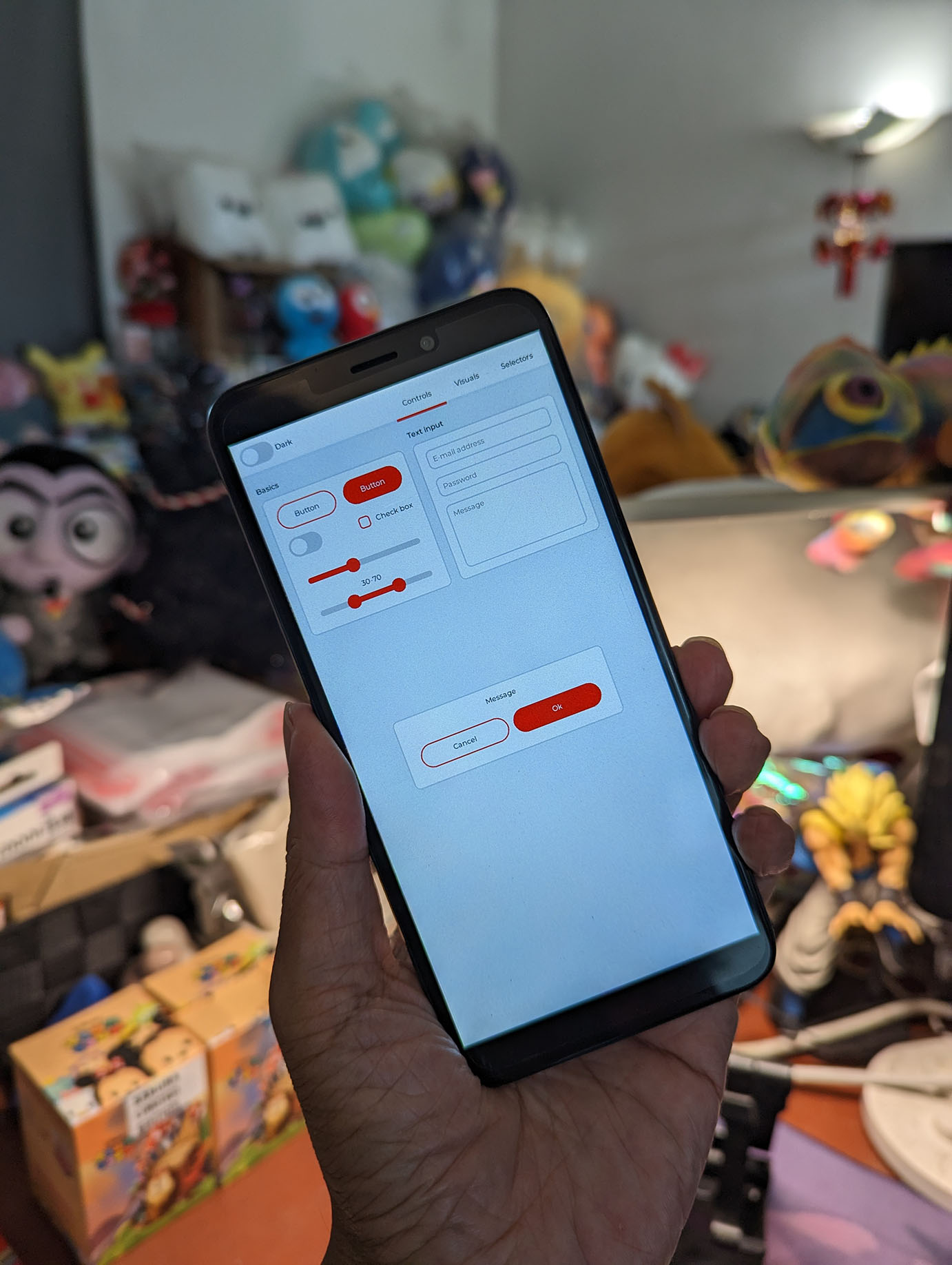
When we run the LVGL Demo App on PinePhone with Apache NuttX RTOS, it renders a dense screen that's not so Touch-Friendly...
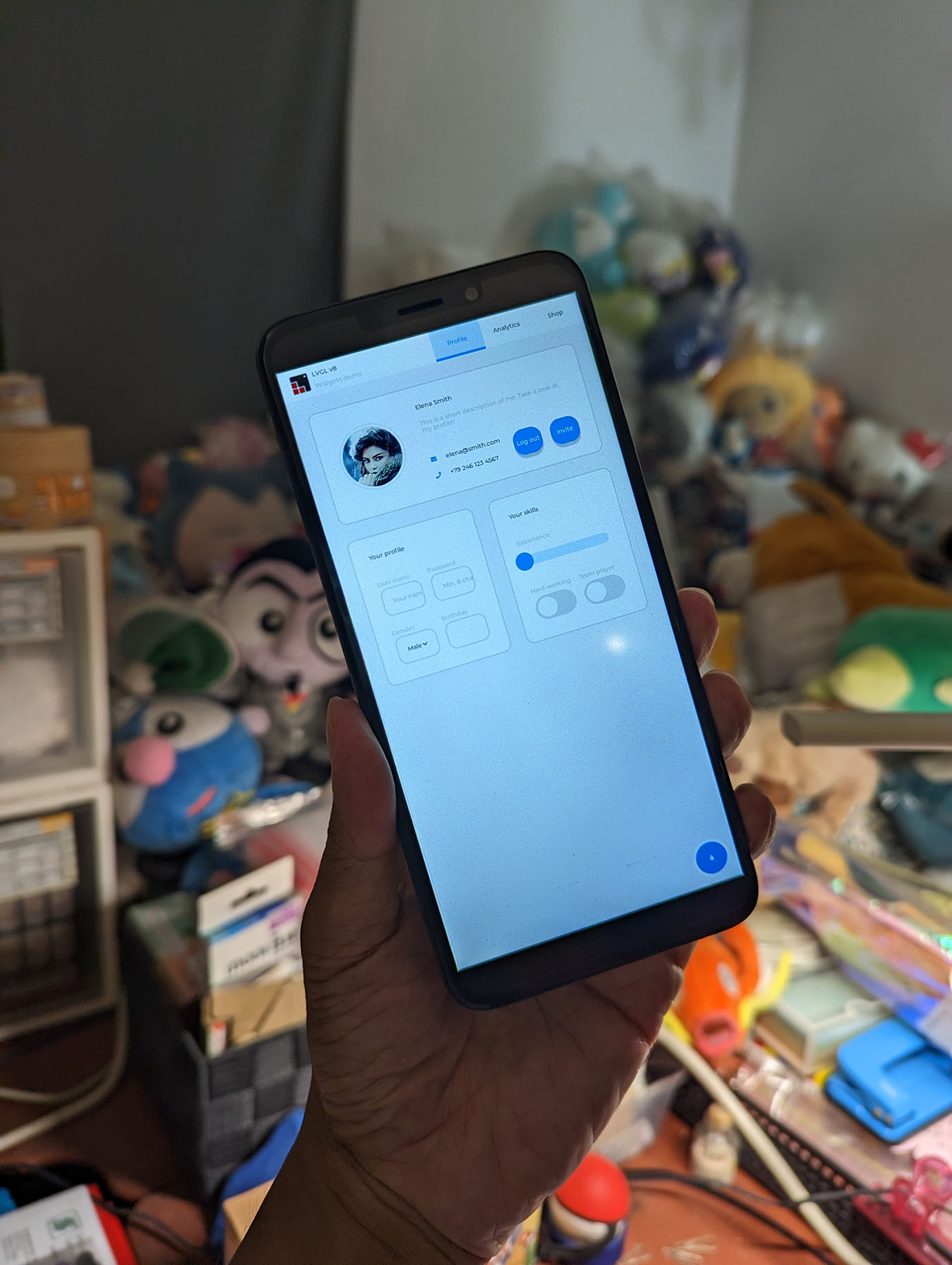
Let's tweak the LVGL Settings to make our LVGL App more accessible. Modify this LVGL Source File...
apps/graphics/lvgl/lvgl/demos/widgets/lv_demo_widgets.c
// Insert this
#include <stdio.h>
// Modify this function
void lv_demo_widgets(void)
{
// Note: PinePhone has width 720 pixels.
// LVGL will set Display Size to Large, which looks really tiny.
// Shouldn't this code depend on DPI? (267 DPI for PinePhone)
if(LV_HOR_RES <= 320) disp_size = DISP_SMALL;
else if(LV_HOR_RES < 720) disp_size = DISP_MEDIUM;
else disp_size = DISP_LARGE;
// Insert this: Print warning if font is missing
#undef LV_LOG_WARN
#define LV_LOG_WARN(s) puts(s)
// Insert this: Change Display Size from Large to Medium, to make Widgets easier to tap
printf("Before: disp_size=%d\n", disp_size);
disp_size = DISP_MEDIUM;
printf("After: disp_size=%d\n", disp_size);
// Existing Code
font_large = LV_FONT_DEFAULT;
font_normal = LV_FONT_DEFAULT;
lv_coord_t tab_h;
if(disp_size == DISP_LARGE) {
...
}
// For Medium Display Size...
else if(disp_size == DISP_MEDIUM) {
// Change this: Increase Tab Height from 45 to 70, to make Tabs easier to tap
tab_h = 70;
// Previously: tab_h = 45;
#if LV_FONT_MONTSERRAT_20
font_large = &lv_font_montserrat_20;
#else
LV_LOG_WARN("LV_FONT_MONTSERRAT_20 is not enabled for the widgets demo. Using LV_FONT_DEFAULT instead.");
#endif
#if LV_FONT_MONTSERRAT_14
font_normal = &lv_font_montserrat_14;
#else
LV_LOG_WARN("LV_FONT_MONTSERRAT_14 is not enabled for the widgets demo. Using LV_FONT_DEFAULT instead.");
#endif
}(Maybe we should modify the code above to include DPI? PinePhone's Display has 267 DPI)
Configure LVGL with these settings...
And add the fonts...
-
Browse into "LVGL > LVGL Configuration"
-
In "Font usage > Enable built-in fonts"
Enable "Montserrat 20"
-
The LVGL Demo App is now less dense and easier to use...
-
(Shot at ISO 800, F/5.6, Manual Focus on Sony NEX-7. Post-processed for Brightness, Constrast and White Point)
What if we increase the Default Font Size? From Montserrat 14 to Montserrat 20?
Let's increase the Default Font Size from 14 to 20...
-
Browse into "LVGL > LVGL Configuration"
-
In "Font usage > Select theme default title font"
Select "Montserrat 20"
-
We run the LVGL Demo App as is, leaving Display Size disp_size as default DISP_LARGE.
Now the text is legible, but some controls are squished...
-
(Shot at ISO 400, F/5.0, Manual Focus, Exposure 0.3 on Sony NEX-7. No post-processing)
We need to increase the Default Font Size from 14 to 20, AND set Display Size disp_size to DISP_MEDIUM. And we will get this...
More details here...
We've seen the LVGL Widgets Demo on NuttX for PinePhone. What about other demos?
Yep there are 5 LVGL Demos available in make menuconfig...
-
Browse into "LVGL > LVGL Configuration"
-
In "Demos", select one or more of the these demos...
"Show Some Widgets"
"Demonstrate the usage of encoder and keyboard"
"Benchmark your system"
"Stress test for LVGL"
"Music player demo"
-
For Music Player Demo, we need these fonts...
-
Browse into "LVGL > LVGL Configuration"
-
In "Font usage", select...
"Montserrat 16"
"Montserrat 20"
"Montserrat 22"
"Montserrat 32"
-
To run the demos on PinePhone...
nsh> lvgldemo
Usage: lvgldemo demo_name
demo_name:
widgets
keypad_encoder
benchmark
stress
music
We've seen the LVGL Widgets Demo...
Here's the LVGL Music Player Demo...
And the LVGL Benchmark Demo...
From the video we see the LVGL Benchmark Numbers...
- Weighted Frames Per Second: 20
- Opa Speed: 100%
| Slow but common cases | Frames Per Sec |
|---|---|
| Image RGB | 19 |
| Image RGB + Opa | 17 |
| Image ARGB | 18 |
| Image ARGB + Opa | 17 |
| Image ARGB Recolor | 17 |
| Image ARGB Recolor + Opa | 16 |
| Substr Image | 19 |
| All Cases | Frames Per Sec |
|---|---|
| Rectangle | 24 |
| Rectangle + Opa | 23 |
| Rectangle Rounded | 23 |
| Rectangle Rounded + Opa | 21 |
| Circle | 23 |
| Circle + Opa | 20 |
| Border | 24 |
| Border + Opa | 24 |
| Border Rounded | 24 |
| (Many many more) |
More details here...
Note that the LVGL Demos start automatically when NuttX boots on PinePhone. Let's talk about this...
Can we boot NuttX on PinePhone, directly to LVGL? Without a Serial Cable?
Sure can! In the previous section we talked about selecting the LVGL Demos.
To boot directly to an LVGL Demo, make sure only 1 LVGL Demo is selected.
Then in make menuconfig...
-
RTOS Features > Tasks and Scheduling
-
Set "Application entry point" to
lvgldemo_main(INIT_ENTRYPOINT)
-
Set "Application entry name" to
lvgldemo_main(INIT_ENTRYNAME)
-
-
Application Configuration > NSH Library
-
Disable "Have architecture-specific initialization"
(NSH_ARCHINIT)
-
NuttX on PinePhone now boots to the LVGL Touchscreen Demo, without a Serial Cable! (Pic below)
Why disable "NSH Architecture-Specific Initialization"?
Normally the NSH NuttX Shell initialises the Display Driver and Touch Panel on PinePhone.
But since we're not running NSH Shell, we'll have to initialise the Display Driver and Touch Panel in our LVGL Demo App.
This is explained here...
Now that we can boot NuttX to an LVGL Touchscreen App, what next?
Maybe we can create an LVGL Terminal App? That will let us interact with the NSH NuttX Shell?
LVGL already provides an Onscreen Keyboard that works on PinePhone NuttX.
More details here...
Read the article...
Now that we can render LVGL Graphical User Interfaces, let's handle Touch Input!
Here's everything we know about PinePhone's Touch Panel...
According to our Test Code...
-
I2C Address is 0x5D
-
I2C Frequency is 400 kHz
(What's the max?)
-
I2C Register Addresses are 16-bit
(Send MSB before LSB, so we should swap the bytes)
-
Reading I2C Register 0x8140 (Product ID) will return the bytes...
39 31 37 53Which is ASCII for "
917S"(Goodix GT917S Touch Panel)
This is how we read the Product ID from the Touch Panel: pinephone_bringup.c
// Product ID (LSB 4 bytes)
#define GOODIX_REG_ID 0x8140
// Read Touch Panel over I2C
static void touch_panel_read(struct i2c_master_s *i2c)
{
uint32_t freq = 400000; // 400 kHz
uint16_t addr = 0x5d; // Default I2C Address for Goodix GT917S
uint16_t reg = GOODIX_REG_ID; // Read Product ID
uint8_t regbuf[2] = { reg >> 8, reg & 0xff }; // Flip the bytes
// Erase the receive buffer
uint8_t buf[4];
ssize_t buflen = sizeof(buf);
memset(buf, 0xff, sizeof(buf));
// Compose the I2C Messages
struct i2c_msg_s msgv[2] =
{
{
.frequency = freq,
.addr = addr,
.flags = 0,
.buffer = regbuf,
.length = sizeof(regbuf)
},
{
.frequency = freq,
.addr = addr,
.flags = I2C_M_READ,
.buffer = buf,
.length = buflen
}
};
// Execute the I2C Transfer
int ret = I2C_TRANSFER(i2c, msgv, 2);
if (ret < 0) { _err("I2C Error: %d\n", ret); return; }
// Dump the receive buffer
infodumpbuffer("buf", buf, buflen);
// Shows "39 31 37 53" or "917S"
}To detect Touch Events, we'll need to handle the Interrupts triggered by Touch Panel.
Based on our research, PinePhone's Touch Panel Interrupt (CTP-INT) is connected at PH4.
Right now we poll PH4 (instead of handling interrupts) because it's easier: pinephone_bringup.c
// Test Touch Panel Interrupt by Polling as GPIO Input.
// Touch Panel Interrupt (CTP-INT) is at PH4.
// Configure for GPIO Input
#define CTP_INT (PIO_INPUT | PIO_PORT_PIOH | PIO_PIN4)
static void touch_panel_read(struct i2c_master_s *i2c);
// Poll for Touch Panel Interrupt (PH4) by reading as GPIO Input
void touch_panel_initialize(struct i2c_master_s *i2c)
{
// Configure the Touch Panel Interrupt for GPIO Input
int ret = a64_pio_config(CTP_INT);
DEBUGASSERT(ret == 0);
// Poll the Touch Panel Interrupt as GPIO Input
bool prev_val = false;
for (int i = 0; i < 6000; i++) { // Poll for 60 seconds
// Read the GPIO Input
bool val = a64_pio_read(CTP_INT);
// If value has changed...
if (val != prev_val) {
// Print the value
if (val) { up_putc('+'); }
else { up_putc('-'); }
prev_val = val;
// If we have just transitioned from Low to High...
if (val) {
// Read the Touch Panel over I2C
touch_panel_read(i2c);
}
}
// Wait a while
up_mdelay(10);
}
}To read the Touch Coordinates, we do this: pinephone_bringup.c
#define GOODIX_REG_ID 0x8140
#define GOODIX_READ_COORD_ADDR 0x814E
#define GOODIX_POINT1_X_ADDR 0x8150
// Read Touch Panel over I2C
static void touch_panel_read(struct i2c_master_s *i2c)
{
// Read the Product ID
uint8_t id[4];
touch_panel_i2c_read(i2c, GOODIX_REG_ID, id, sizeof(id));
// Shows "39 31 37 53" or "917S"
// Read the Touch Panel Status
uint8_t status[1];
touch_panel_i2c_read(i2c, GOODIX_READ_COORD_ADDR, status, sizeof(status));
// Shows "81"
const uint8_t status_code = status[0] & 0x80; // Set to 0x80
const uint8_t touched_points = status[0] & 0x0f; // Set to 0x01
if (status_code != 0 && // If Touch Panel Status is OK and...
touched_points >= 1) { // Touched Points is 1 or more
// Read the First Touch Coordinates
uint8_t touch[6];
touch_panel_i2c_read(i2c, GOODIX_POINT1_X_ADDR, touch, sizeof(touch));
// Shows "92 02 59 05 1b 00"
// Decode the Touch Coordinates
const uint16_t x = touch[0] + (touch[1] << 8);
const uint16_t y = touch[2] + (touch[3] << 8);
_info("touch x=%d, y=%d\n", x, y);
// Shows "touch x=658, y=1369"
}
// Set the Touch Panel Status to 0
touch_panel_set_status(i2c, 0);
}When we touch PinePhone near the Lower Right Corner, we see the Touch Coordinates x=658, y=1369 (which is quite close to the 720 x 1440 screen size)...
twi_transfer: TWI0 count: 1
twi_wait: TWI0 Waiting...
twi_put_addr: TWI address 7bits+r/w = 0xba
twi_wait: TWI0 Awakened with result: 0
-+twi_transfer: TWI0 count: 2
twi_wait: TWI0 Waiting...
twi_put_addr: TWI address 7bits+r/w = 0xba
twi_put_addr: TWI address 7bits+r/w = 0xbb
twi_wait: TWI0 Awakened with result: 0
buf (0x40a8fd18):
0000 39 31 37 53 917S
twi_transfer: TWI0 count: 2
twi_wait: TWI0 Waiting...
twi_put_addr: TWI address 7bits+r/w = 0xba
twi_put_addr: TWI address 7bits+r/w = 0xbb
twi_wait: TWI0 Awakened with result: 0
buf (0x40a8fd08):
0000 81 .
twi_transfer: TWI0 count: 2
twi_wait: TWI0 Waiting...
twi_put_addr: TWI address 7bits+r/w = 0xba
twi_put_addr: TWI address 7bits+r/w = 0xbb
twi_wait: TWI0 Awakened with result: 0
buf (0x40a8fd20):
0000 92 02 59 05 1b 00 ..Y...
touch_panel_read: touch x=658, y=1369
Yep we can read the Touch Coordinates correctly, with polling! (But not so efficient)
Let's handle Interrupts from the Touch Panel...
In the previous section we've read the Touch Panel by Polling. Which is easier but inefficient.
Eventually we'll use an Interrupt Handler to monitor Touch Panel Interrupts. This is how we monitor PH4 for interrupts: pinephone_bringup.c
// Touch Panel Interrupt (CTP-INT) is at PH4
#define CTP_INT (PIO_EINT | PIO_PORT_PIOH | PIO_PIN4)
// Register the Interrupt Handler for Touch Panel
void touch_panel_initialize(void) {
// Attach the PIO Interrupt Handler for Port PH
if (irq_attach(A64_IRQ_PH_EINT, touch_panel_interrupt, NULL) < 0) {
_err("irq_attach failed\n");
return ERROR;
}
// Enable the PIO Interrupt for Port PH
up_enable_irq(A64_IRQ_PH_EINT);
// Configure the Touch Panel Interrupt
int ret = a64_pio_config(CTP_INT);
DEBUGASSERT(ret == 0);
// Enable the Touch Panel Interrupt
ret = a64_pio_irqenable(CTP_INT);
DEBUGASSERT(ret == 0);
}
// Interrupt Handler for Touch Panel
static int touch_panel_interrupt(int irq, void *context, void *arg) {
// Print something when interrupt is triggered
up_putc('.');
return OK;
}When we run this code, it generates a non-stop stream of "." characters.
Which means that the Touch Input Interrupt is generated continuously. Without touching the screen!
Is our Interrupt Handler code correct?
Yep our Interrupt Handler code is correct! But through our experiments we discovered one thing...
To stop the repeated Touch Input Interrupts, we need to set the Touch Panel Status to 0! Like so: pinephone_bringup.c
// When the Touch Input Interrupt is triggered...
// Set the Touch Panel Status to 0
touch_panel_set_status(i2c, 0);
...
#define GOODIX_READ_COORD_ADDR 0x814E // Touch Panel Status (Read / Write)
#define CTP_FREQ 400000 // I2C Frequency: 400 kHz
#define CTP_I2C_ADDR 0x5d // Default I2C Address for Goodix GT917S
// Set the Touch Panel Status
static int touch_panel_set_status(
struct i2c_master_s *i2c, // I2C Bus
uint8_t status // Status value to be set
) {
uint16_t reg = GOODIX_READ_COORD_ADDR; // I2C Register
uint32_t freq = CTP_FREQ; // 400 kHz
uint16_t addr = CTP_I2C_ADDR; // Default I2C Address for Goodix GT917S
uint8_t buf[3] = {
reg >> 8, // Swap the bytes
reg & 0xff, // Swap the bytes
status
};
// Compose the I2C Message
struct i2c_msg_s msgv[1] =
{
{
.frequency = freq,
.addr = addr,
.flags = 0,
.buffer = buf,
.length = sizeof(buf)
}
};
// Execute the I2C Transfer
const int msgv_len = sizeof(msgv) / sizeof(msgv[0]);
int ret = I2C_TRANSFER(i2c, msgv, msgv_len);
if (ret < 0) { _err("I2C Error: %d\n", ret); return ret; }
return OK;
}So we set the Touch Panel Status inside our Interrupt Handler?
But Interrupt Handlers aren't allowed to make I2C Calls!
We need to forward the Interrupt to a Background Thread to handle. Like so: pinephone_bringup.c
// Interrupt Handler for Touch Panel
static int gt9xx_isr_handler(int irq, FAR void *context, FAR void *arg)
{
FAR struct gt9xx_dev_s *priv = (FAR struct gt9xx_dev_s *)arg;
// Set the Interrupt Pending Flag
irqstate_t flags = enter_critical_section();
priv->int_pending = true;
leave_critical_section(flags);
// Notify the Poll Waiters
poll_notify(priv->fds, GT9XX_NPOLLWAITERS, POLLIN);
return 0;
}This notifies the File Descriptors fds that are waiting for Touch Input Interrupts to be triggered.
When the File Descriptor is notified, the Background Thread will become unblocked, and can call I2C to read the Touch Input.
Right now we don't have a Background Thread, so we poll and wait for the Touch Input Interrupt to be triggered: pinephone_bringup.c
// Poll for Touch Panel Interrupt
// TODO: Move this
for (int i = 0; i < 6000; i++) { // Poll for 60 seconds
// If Touch Panel Interrupt has been triggered...
if (priv->int_pending) {
// Read the Touch Panel over I2C
touch_panel_read(i2c_dev);
// Reset the Interrupt Pending Flag
priv->int_pending = false;
}
// Wait a while
up_mdelay(10); // 10 milliseconds
}And it works!
- Ready to Boot CPU
- Boot from EL2
- Boot from EL1
- Boot to C runtime for OS Initialize
a64_pio_config: cfgaddr=0x1c208fc, intaddr=0x1c20a40, value=0x0, shift=16
touch_panel_initialize: v=0x10, m=0x10, a=0x1c20a50
buf (0x40a8fd20):
0000 39 31 37 53 917S
buf (0x40a8fd10):
0000 81 .
buf (0x40a8fd28):
0000 19 01 e6 02 2a 00 ....*.
touch_panel_read: touch x=281, y=742
...
buf (0x40a8fd20):
0000 39 31 37 53 917S
buf (0x40a8fd10):
0000 81 .
buf (0x40a8fd28):
0000 81 02 33 00 25 00 ..3.%.
touch_panel_read: touch x=641, y=51
...
buf (0x40a8fd20):
0000 39 31 37 53 917S
buf (0x40a8fd10):
0000 81 .
buf (0x40a8fd28):
0000 0f 00 72 05 14 00 ..r...
touch_panel_read: touch x=15, y=1394
Let's move this code into the NuttX Touch Panel Driver for PinePhone...
We moved the code above into the NuttX Touch Panel Driver for PinePhone...
This is how we start the driver when NuttX boots: pinephone_bringup.c
#define CTP_I2C_ADDR 0x5d // Default I2C Address for Goodix GT917S
ret = gt9xx_register("/dev/input0", i2c, CTP_I2C_ADDR, &g_pinephone_gt9xx);And it works with the LVGL Demo App!
Read the article...
Read the article...
Let's create a Terminal App in LVGL, that will let us interact with the NuttX NSH Shell...
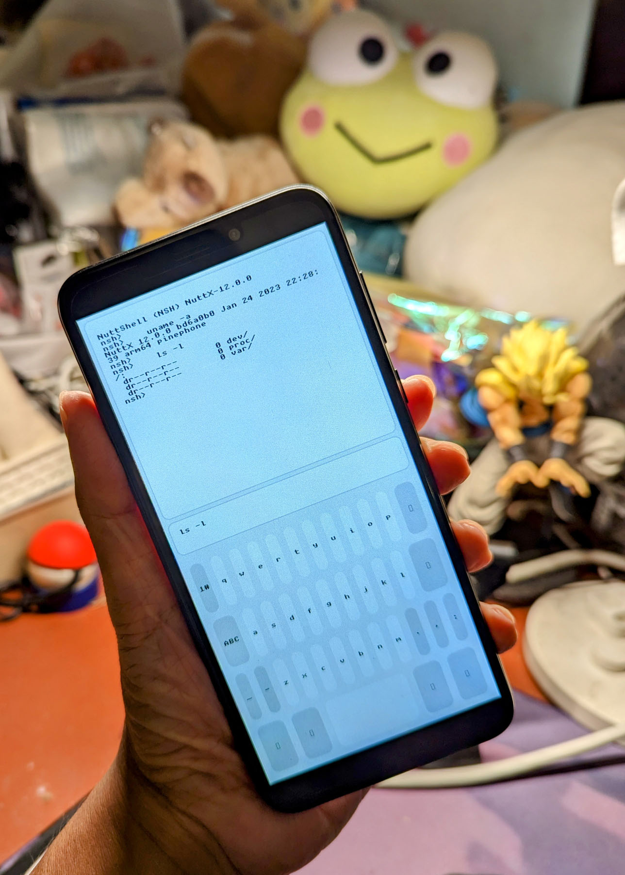
We begin by starting the NSH Task and piping a command to NSH Shell...
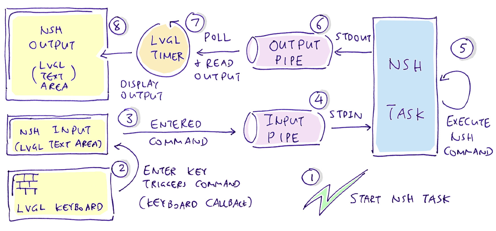
Our LVGL Terminal App needs to...
-
Start the NuttX Task for NSH Shell
-
Redirect the NSH Console Input / Output to LVGL
Here's a simple test that starts the NSH Task and sends a command to NSH Console via a POSIX Pipe: lvgldemo.c
void test_terminal(void) {
// Create the pipes
int nsh_stdin[2];
int nsh_stdout[2];
int nsh_stderr[2];
int ret;
ret = pipe(nsh_stdin); if (ret < 0) { _err("stdin pipe failed: %d\n", errno); return; }
ret = pipe(nsh_stdout); if (ret < 0) { _err("stdout pipe failed: %d\n", errno); return; }
ret = pipe(nsh_stderr); if (ret < 0) { _err("stderr pipe failed: %d\n", errno); return; }
// Close default stdin, stdout and stderr
close(0);
close(1);
close(2);
// Use the pipes as stdin, stdout and stderr
#define READ_PIPE 0 // Read Pipes: stdin, stdout, stderr
#define WRITE_PIPE 1 // Write Pipes: stdin, stdout, stderr
dup2(nsh_stdin[READ_PIPE], 0);
dup2(nsh_stdout[WRITE_PIPE], 1);
dup2(nsh_stderr[WRITE_PIPE], 2);
// Create a new NSH Task using the pipes
char *argv[] = { NULL };
pid_t pid = task_create(
"NSH Console",
100, // Priority
CONFIG_DEFAULT_TASK_STACKSIZE,
nsh_consolemain,
argv
);
if (pid < 0) { _err("task_create failed: %d\n", errno); return; }
_info("pid=%d\n", pid);
// Wait a while
sleep(1);
// Send a few commands to NSH
for (int i = 0; i < 5; i++) {
// Send a command to NSH stdin
const char cmd[] = "ls\r";
ret = write(
nsh_stdin[WRITE_PIPE],
cmd,
sizeof(cmd)
);
_info("write nsh_stdin: %d\n", ret);
// Wait a while
sleep(1);
// Read the output from NSH stdout.
// TODO: This will block if there's nothing to read.
static char buf[64];
ret = read(
nsh_stdout[READ_PIPE],
buf,
sizeof(buf) - 1
);
if (ret > 0) { buf[ret] = 0; _info("%s\n", buf); }
// Wait a while
sleep(1);
#ifdef NOTUSED
// Read the output from NSH stderr.
// TODO: This will block if there's nothing to read.
ret = read(
nsh_stderr[READ_PIPE],
buf,
sizeof(buf) - 1
);
if (ret > 0) { buf[ret] = 0; _info("%s\n", buf); }
#endif
}
}And it works! Here's the NSH Task auto-running the ls Command received via our Pipe...
NuttShell (NSH) NuttX-12.0.0
nsh> ls
/:
dev/
var/
nsh> est_terminal: write nsh_stdin: 9
test_terminal: read nsh_stdout: 63
test_terminal: K
...
nsh> ls
/:
dev/
var/
test_terminal: write nsh_stdin: 9
test_terminal: read nsh_stdout: 63
test_terminal:
...
There's a problem with the code above... Calling read() on nsh_stdout will block if there's no NSH Output to be read.
Let's call poll() on nsh_stdout to check if there's NSH Output to be read...
In the previous sections we started an NSH Shell that will execute NSH Commands that we pipe to it.
But there's a problem: Calling read() on nsh_stdout will block if there's no NSH Output to be read. And we can't block our LVGL App, since it needs to handle UI Events periodically.
Solution: We call has_input to check if there's NSH Output ready to be read, before reading the output: lvgldemo.c
// Read the output from NSH stdout
static char buf[64];
if (has_input(nsh_stdout[READ_PIPE])) {
ret = read(
nsh_stdout[READ_PIPE],
buf,
sizeof(buf) - 1
);
if (ret > 0) { buf[ret] = 0; _info("%s\n", buf); }
}
// Read the output from NSH stderr
if (has_input(nsh_stderr[READ_PIPE])) {
ret = read(
nsh_stderr[READ_PIPE],
buf,
sizeof(buf) - 1
);
if (ret > 0) { buf[ret] = 0; _info("%s\n", buf); }
}has_input calls poll() on nsh_stdout to check if there's NSH Output ready to be read: lvgldemo.c
// Return true if the File Descriptor has data to be read
static bool has_input(int fd) {
// Poll the File Descriptor for Input
struct pollfd fdp;
fdp.fd = fd;
fdp.events = POLLIN;
int ret = poll(
(struct pollfd *)&fdp, // File Descriptors
1, // Number of File Descriptors
0 // Poll Timeout (Milliseconds)
);
if (ret > 0) {
// If Poll is OK and there is Input...
if ((fdp.revents & POLLIN) != 0) {
// Report that there's Input
_info("has input: fd=%d\n", fd);
return true;
}
// Else report No Input
_info("no input: fd=%d\n", fd);
return false;
} else if (ret == 0) {
// Ignore Timeout
_info("timeout: fd=%d\n", fd);
return false;
} else if (ret < 0) {
// Handle Error
_err("poll failed: %d, fd=%d\n", ret, fd);
return false;
}
// Never comes here
DEBUGASSERT(false);
return false;
}has_input returns True if there's NSH Output waiting to be read...
has_input: has input: fd=8
And has_input returns False (due to timeout) if there's nothing waiting to be read...
has_input: timeout: fd=8
This polling needs to be done in an LVGL Timer, here's why...
In the previous sections we started an NSH Shell that will execute NSH Commands that we pipe to it.
Our LVGL Terminal for NSH Shell shall periodically check for output from the NSH Shell, and write the output to the LVGL Display...
-
Every couple of milliseconds...
-
We call
poll()to check if NSH Shell has output data -
We read the output from NSH Shell
-
We display the NSH Output in an LVGL Label Widget
-
We'll do this with an LVGL Timer like so: lvgldemo.c
// Create an LVGL Terminal that will let us interact with NuttX NSH Shell
void test_terminal(void) {
// Create an LVGL Timer to poll for output from NSH Shell
static uint32_t user_data = 10;
lv_timer_t *timer = lv_timer_create(
my_timer, // Callback
5000, // Timer Period (Milliseconds)
&user_data // Callback Data
);my_timer is our Timer Callback Function: lvgldemo.c
// Callback for LVGL Timer
void my_timer(lv_timer_t *timer) {
// Get the Callback Data
uint32_t *user_data = timer->user_data;
_info("my_timer called with callback data: %d\n", *user_data);
*user_data += 1;
// TODO: Call poll() to check if NSH Stdout has output to be read
// TODO: Read the NSH Stdout
// TODO: Write the NSH Output to LVGL Label Widget
}When we run this, LVGL calls our Timer Callback Function every 5 seconds...
my_timer: my_timer called with callback data: 10
my_timer: my_timer called with callback data: 11
my_timer: my_timer called with callback data: 12
Why poll for NSH Output? Why not run a Background Thread that will block on NSH Output?
If we ran a Background Thread that will block until NSH Output is available, we still need to write the NSH Output to an LVGL Widget for display.
But LVGL is NOT Thread-Safe. Thus we need a Mutex to lock the LVGL Widgets, which gets messy.
For now, it's simpler to run an LVGL Timer to poll for NSH Output.
Let's add the polling to the LVGL Timer Callback...
In the previous section we've created an LVGL Timer that's triggered periodically.
Inside the LVGL Timer Callback, let's poll the NSH Output and check if there's any output to be read: lvgldemo.c
// Callback for LVGL Timer
static void my_timer(lv_timer_t *timer) {
...
// Read the output from NSH stdout
static char buf[64];
DEBUGASSERT(nsh_stdout[READ_PIPE] != 0);
if (has_input(nsh_stdout[READ_PIPE])) {
ret = read(
nsh_stdout[READ_PIPE],
buf,
sizeof(buf) - 1
);
_info("read nsh_stdout: %d\n", ret);
if (ret > 0) { buf[ret] = 0; _info("%s\n", buf); }
}
// Read the output from NSH stderr
DEBUGASSERT(nsh_stderr[READ_PIPE] != 0);
if (has_input(nsh_stderr[READ_PIPE])) {
ret = read(
nsh_stderr[READ_PIPE],
buf,
sizeof(buf) - 1
);
_info("read nsh_stderr: %d\n", ret);
if (ret > 0) { buf[ret] = 0; _info("%s\n", buf); }
}
// TODO: Write the NSH Output to LVGL Label WidgetNSH won't emit any output until we run some NSH Commands. So let's trigger some NSH Commands inside the LVGL Timer Callback: lvgldemo.c
// Callback for LVGL Timer
static void my_timer(lv_timer_t *timer) {
// Get the Callback Data
uint32_t *user_data = timer->user_data;
_info("my_timer called with callback data: %d\n", *user_data);
*user_data += 1;
// Send a command to NSH stdin
if (*user_data % 5 == 0) {
const char cmd[] = "ls\r";
DEBUGASSERT(nsh_stdin[WRITE_PIPE] != 0);
ret = write(
nsh_stdin[WRITE_PIPE],
cmd,
sizeof(cmd)
);
_info("write nsh_stdin: %d\n", ret);
}
// Read the output from NSH stdout
...When we run this, we see the LVGL Timer Callback sending NSH Commands and printing the NSH Output...
my_timer: my_timer called with callback data: 10
has_input: has input: fd=8
my_timer: read nsh_stdout: 63
my_timer: createWidgetsWrapped: start
createWidgetsWrapped: end
NuttShel
has_input: timeout: fd=10
my_timer: my_timer called with callback data: 11
has_input: has input: fd=8
my_timer: read nsh_stdout: 29
my_timer: l (NSH) NuttX-12.0.0
nsh>
has_input: timeout: fd=10
my_timer: my_timer called with callback data: 12
has_input: timeout: fd=8
has_input: timeout: fd=10
my_timer: my_timer called with callback data: 13
has_input: timeout: fd=8
has_input: timeout: fd=10
my_timer: my_timer called with callback data: 14
my_timer: write nsh_stdin: 4
has_input: timeout: fd=8
has_input: timeout: fd=10
my_timer: my_timer called with callback data: 15
has_input: has input: fd=8
my_timer: read nsh_stdout: 33
my_timer: ls
/:
dev/
proc/
var/
nsh>
Now that our background processing is ready, let's render the LVGL Widgets for our terminal...
Our LVGL Terminal will have 3 LVGL Widgets...
-
LVGL Text Area Widget that shows the NSH Output
(At the top)
-
LVGL Text Area Widget for NSH Input, to enter commands
(At the middle)
-
LVGL Keyboard Widget for typing commands into NSH Input
(At the bottom)
This is how we render the 3 LVGL Widgets: lvgldemo.c
// PinePhone LCD Panel Width and Height (pixels)
#define PINEPHONE_LCD_PANEL_WIDTH 720
#define PINEPHONE_LCD_PANEL_HEIGHT 1440
// Margin of 10 pixels all around
#define TERMINAL_MARGIN 10
// Terminal Width is LCD Width minus Left and Right Margins
#define TERMINAL_WIDTH (PINEPHONE_LCD_PANEL_WIDTH - 2 * TERMINAL_MARGIN)
// Keyboard is Lower Half of LCD.
// Terminal Height is Upper Half of LCD minus Top and Bottom Margins.
#define TERMINAL_HEIGHT ((PINEPHONE_LCD_PANEL_HEIGHT / 2) - 2 * TERMINAL_MARGIN)
// Height of Input Text Area
#define INPUT_HEIGHT 100
// Height of Output Text Area is Terminal Height minus Input Height minus Middle Margin
#define OUTPUT_HEIGHT (TERMINAL_HEIGHT - INPUT_HEIGHT - TERMINAL_MARGIN)
// Create the LVGL Widgets for the LVGL Terminal.
// Based on https://docs.lvgl.io/master/widgets/keyboard.html#keyboard-with-text-area
static void create_widgets(void) {
// Create an LVGL Keyboard Widget
lv_obj_t *kb = lv_keyboard_create(lv_scr_act());
// Create an LVGL Text Area Widget for NSH Output
output = lv_textarea_create(lv_scr_act());
lv_obj_align(output, LV_ALIGN_TOP_LEFT, TERMINAL_MARGIN, TERMINAL_MARGIN);
lv_textarea_set_placeholder_text(output, "Hello");
lv_obj_set_size(output, TERMINAL_WIDTH, OUTPUT_HEIGHT);
// Create an LVGL Text Area Widget for NSH Input
input = lv_textarea_create(lv_scr_act());
lv_obj_align(input, LV_ALIGN_TOP_LEFT, TERMINAL_MARGIN, OUTPUT_HEIGHT + 2 * TERMINAL_MARGIN);
lv_obj_add_event_cb(input, input_callback, LV_EVENT_ALL, kb);
lv_obj_set_size(input, TERMINAL_WIDTH, INPUT_HEIGHT);
// Set the Keyboard to populate the NSH Input Text Area
lv_keyboard_set_textarea(kb, input);
}input_callback is the Callback Function for our LVGL Keyboard. Which we'll cover in a while.
Note that we're using the LVGL Default Font for all 3 LVGL Widgets. Which has a problem...
Our LVGL Terminal looks nicer with a Monospace Font.
But watch what happens if we change the LVGL Default Font from Montserrat 20 (proportional) to UNSCII 16 (monospace)...
The LVGL Keyboard has missing symbols! Enter, Backspace, ...
Thus we set the LVGL Default Font back to Montserrat 20.
And instead we set the Font Style for NSH Input and Output to UNSCII 16: lvgldemo.c
// Set the Font Style for NSH Input and Output to a Monospaced Font
static lv_style_t terminal_style;
lv_style_init(&terminal_style);
lv_style_set_text_font(&terminal_style, &lv_font_unscii_16);
// Create an LVGL Text Area Widget for NSH Output
output = lv_textarea_create(lv_scr_act());
lv_obj_add_style(output, &terminal_style, 0);
...
// Create an LVGL Text Area Widget for NSH Input
input = lv_textarea_create(lv_scr_act());
lv_obj_add_style(input, &terminal_style, 0);
...Now we see the LVGL Keyboard without missing symbols (pic below)...
Let's look at our Callback Function for the LVGL Keyboard...
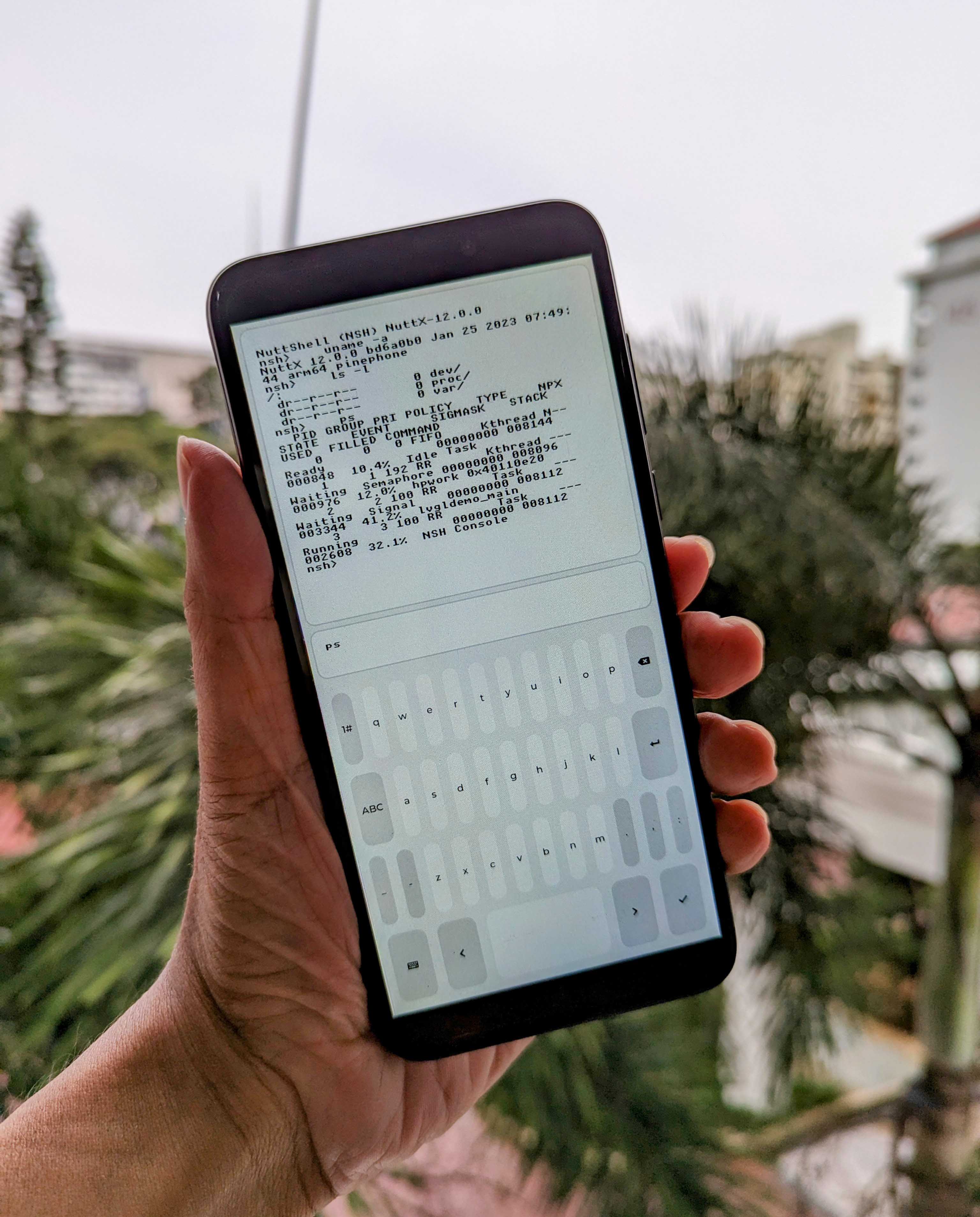
Here's the Callback Function that handles input from the LVGL Keyboard.
It waits for the Enter key to be pressed, then it sends the typed command to NSH Shell via a POSIX Pipe: lvgldemo.c
// Callback Function for NSH Input Text Area.
// Based on https://docs.lvgl.io/master/widgets/keyboard.html#keyboard-with-text-area
static void input_callback(lv_event_t *e) {
int ret;
// Decode the LVGL Event
const lv_event_code_t code = lv_event_get_code(e);
// If Enter has been pressed, send the Command to NSH Input
if (code == LV_EVENT_VALUE_CHANGED) {
// Get the Keyboard Widget from the LVGL Event
const lv_obj_t *kb = lv_event_get_user_data(e);
DEBUGASSERT(kb != NULL);
// Get the Button Index of the Keyboard Button Pressed
const uint16_t id = lv_keyboard_get_selected_btn(kb);
// Get the Text of the Keyboard Button
const char *key = lv_keyboard_get_btn_text(kb, id);
if (key == NULL) { return; }
// If Enter is pressed...
if (key[0] == 0xef && key[1] == 0xa2 && key[2] == 0xa2) {
// Read the NSH Input
DEBUGASSERT(input != NULL);
const char *cmd = lv_textarea_get_text(input);
if (cmd == NULL || cmd[0] == 0) { return; }
// Send the Command to NSH stdin
DEBUGASSERT(nsh_stdin[WRITE_PIPE] != 0);
ret = write(
nsh_stdin[WRITE_PIPE],
cmd,
strlen(cmd)
);
// Erase the NSH Input
lv_textarea_set_text(input, "");
}
}
}The command runs in NSH Shell and produces NSH Output. Which is handled by the LVGL Timer Callback Function...
Our LVGL Timer Callback Function checks periodically whether there's any NSH Output waiting to be processed.
If there's NSH Output, the Callback Function writes the output to the NSH Output Text Area: lvgldemo.c
// Callback Function for LVGL Timer.
// Based on https://docs.lvgl.io/master/overview/timer.html#create-a-timer
static void timer_callback(lv_timer_t *timer) {
// Read the output from NSH stdout
static char buf[64];
DEBUGASSERT(nsh_stdout[READ_PIPE] != 0);
if (has_input(nsh_stdout[READ_PIPE])) {
ret = read(
nsh_stdout[READ_PIPE],
buf,
sizeof(buf) - 1
);
if (ret > 0) {
// Add to NSH Output Text Area
buf[ret] = 0;
remove_escape_codes(buf, ret);
DEBUGASSERT(output != NULL);
lv_textarea_add_text(output, buf);
}
}remove_escape_codes searches for Escape Codes in the NSH Output and replaces them by spaces.
That's why we see 3 spaces between the nsh> prompt and the NSH Command. (Pic below)
For more details, check out the article...
Now that NuttX can run Touchscreen Apps on PinePhone... What next?
Maybe we can turn NuttX on PinePhone into a Feature Phone?
Just Voice Calls and SMS, using PinePhone's LTE Modem.
This is useful because...?
So we can pop a microSD Card (and SIM) into any PinePhone...
And turn it instantly into an Emergency Phone?
What NuttX Drivers would we need?
We need a NuttX Driver for the PinePhone's Quectel LTE Modem.
Which talks over USB Serial. Thus we also need a NuttX Driver for PinePhone's Allwinner A64 USB Controller.
More about this in the next section.
And if there's no LTE Network Coverage? Like in a Natural Disaster?
The Long-Range, Low-Power LoRa Network might be good for search and rescue communications.
(Short Text Messages only plus GPS Geolocation, non-guaranteed message delivery)
Just attach the LoRa Case to PinePhone...
-
(Still in stock!)
We might use JF's Driver...
Or the LoRa Driver that we have ported to NuttX...
Or maybe Meshtastic (with Portduino), since it has a complete LoRa Messaging App...
Will PinePhone on NuttX become a fully-functional smartphone?
Maybe someday? We're still lacking plenty of drivers: WiFi, Bluetooth LE, GPS, Audio, ...
Probably better to start as a Feature Phone (or LoRa Communication) and build up.
Read the articles...
What NuttX Drivers would we need to turn PinePhone into a Feature Phone? (Voice Calls and SMS only)
We need a NuttX Driver for the PinePhone's Quectel LTE Modem...
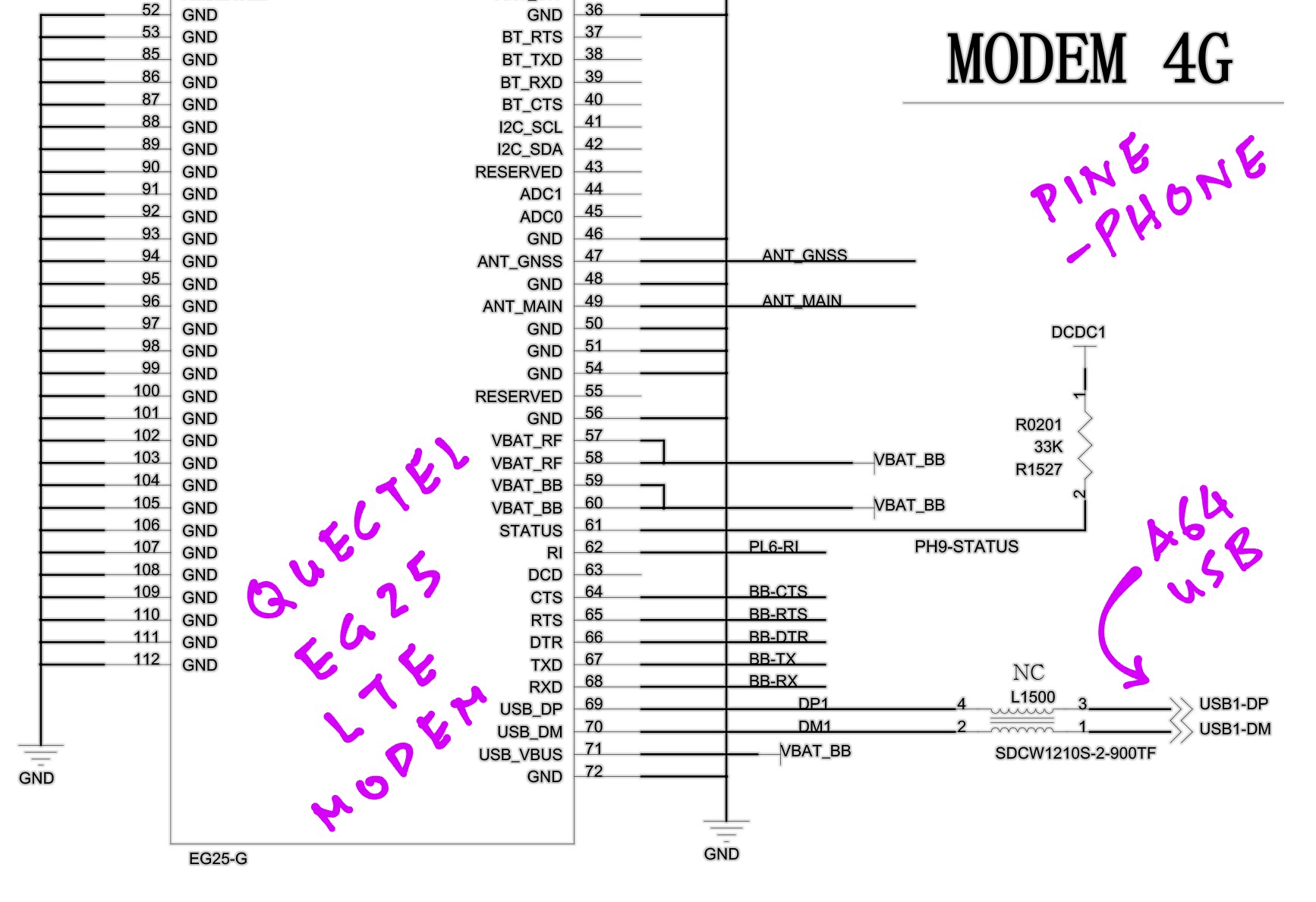
Which talks over USB Serial. Thus we also need a NuttX Driver for PinePhone's Allwinner A64 USB Controller.
Here are the docs for Allwinner A64 USB Controller...
-
Allwinner A64 User Manual, Section 7.5 "USB" (Page 583)
-
Allwinner A20 User Manual, Section 6.7 "USB DRD" (Page 682), Section 6.8 "USB Host" (Page 683)
Any sample code for Allwinner A64 USB?
Refer to the Allwinner A64 USB Drivers in FreeBSD and NetBSD...
-
freebsd/sys/dev/usb/controller/musb_otg_allwinner.c
But Allwinner A64's Official Docs are horrigibly lacking...
Maybe we refer to the NXP i.MX 8 USB Docs, and we compare with the FreeBSD / NetBSD USB Drivers for i.MX 8?
(Since NXP i.MX 8 is so much better documented than Allwinner A64)
How do USB Drivers work in NuttX?
Check out this NuttX Doc on USB Drivers...
And the NuttX USB Driver for STM32...
(USB OTG FS: Able to act as a device/host/OTG peripheral, at full speed 12Mbps)
(USB OTG HS: Able to act as a device/host/OTG peripheral, at full speed 12Mbps or high speed 480Mbps)
How did we get the FreeBSD and NetBSD USB Drivers for Allwinner A64?
PinePhone's Device Tree says that the USB Drivers are...
usb@1c19000 {
compatible = "allwinner,sun8i-a33-musb";
...
phy@1c19400 {
compatible = "allwinner,sun50i-a64-usb-phy";
So we searched for allwinner,sun8i-a33-musb and allwinner,sun50i-a64-usb-phy.
Here's the PinePhone USB Device Tree: sun50i-a64-pinephone-1.2.dts
usb@1c19000 {
compatible = "allwinner,sun8i-a33-musb";
reg = <0x1c19000 0x400>;
clocks = <0x02 0x29>;
resets = <0x02 0x12>;
interrupts = <0x00 0x47 0x04>;
interrupt-names = "mc";
phys = <0x31 0x00>;
phy-names = "usb";
extcon = <0x31 0x00>;
dr_mode = "otg";
status = "okay";
};
phy@1c19400 {
compatible = "allwinner,sun50i-a64-usb-phy";
reg = <0x1c19400 0x14 0x1c1a800 0x04 0x1c1b800 0x04>;
reg-names = "phy_ctrl\0pmu0\0pmu1";
clocks = <0x02 0x56 0x02 0x57>;
clock-names = "usb0_phy\0usb1_phy";
resets = <0x02 0x00 0x02 0x01>;
reset-names = "usb0_reset\0usb1_reset";
status = "okay";
#phy-cells = <0x01>;
usb-role-switch;
phandle = <0x31>;
port {
endpoint {
remote-endpoint = <0x32>;
phandle = <0x47>;
};
};
};
usb@1c1a000 {
compatible = "allwinner,sun50i-a64-ehci\0generic-ehci";
reg = <0x1c1a000 0x100>;
interrupts = <0x00 0x48 0x04>;
clocks = <0x02 0x2c 0x02 0x2a 0x02 0x5b>;
resets = <0x02 0x15 0x02 0x13>;
status = "okay";
};
usb@1c1a400 {
compatible = "allwinner,sun50i-a64-ohci\0generic-ohci";
reg = <0x1c1a400 0x100>;
interrupts = <0x00 0x49 0x04>;
clocks = <0x02 0x2c 0x02 0x5b>;
resets = <0x02 0x15>;
status = "okay";
};
usb@1c1b000 {
compatible = "allwinner,sun50i-a64-ehci\0generic-ehci";
reg = <0x1c1b000 0x100>;
interrupts = <0x00 0x4a 0x04>;
clocks = <0x02 0x2d 0x02 0x2b 0x02 0x5d>;
resets = <0x02 0x16 0x02 0x14>;
phys = <0x31 0x01>;
phy-names = "usb";
status = "okay";
};
usb@1c1b400 {
compatible = "allwinner,sun50i-a64-ohci\0generic-ohci";
reg = <0x1c1b400 0x100>;
interrupts = <0x00 0x4b 0x04>;
clocks = <0x02 0x2d 0x02 0x5d>;
resets = <0x02 0x16>;
phys = <0x31 0x01>;
phy-names = "usb";
status = "okay";
};
Read the article...
We're now upstreaming the driver for 4G LTE Modem to NuttX Mainline...
TODO: Disable UART2 and /dev/ttyS2 so that UART3 maps neatly to /dev/ttyS3. (See this)
This is how we make a Phone Call and send a Text Message...
Read the article...
This is the NuttX App that makes a Phone Call on PinePhone: dial_number
Here's the output...
NuttShell (NSH) NuttX-12.0.3
nsh> hello
// Check Modem Status
Command: AT
Response:
RDY
+CFUN: 1
+CPIN: READY
+QUSIM: 1
+QIND: SMS DONE
// SIM and SMS are ready
// Check Network Status
Command: AT+CREG?
Response:
+CREG: 0,1
+QIND: PB DONE
// Network and Phonebook are ready
// Get Network Operator
Command: AT+COPS?
Response: +COPS: 0,0,"SGP-M1",7
// Get Range of PCM Parameters for Digital Audio
Command: AT+QDAI=?
Response: +QDAI: (1-4),(0,1),(0,1),(0-5),(0-2),(0,1)(1)(1-16)
// Get Current PCM Configuration for Digital Audio
Command: AT+QDAI?
Response: +QDAI: 1,1,0,1,0,0,1,1
// Make Outgoing Phone Call
Command: ATDyourphonenumber;
Response:
OK
// Receiver has hung up
Response:
NO CARRIER
// Hang up Phone Call
Command: ATH
Response: OK
What does this say: +QDAI: 1,1,0,1,0,0,1,1
The above PCM Digital Audio Configuration for the LTE Modem says...
-
io = 1
Digital PCM Output
-
mode = 1
Slave Mode
-
fsync = 0
Primary Mode (short-synchronization)
-
clock = 1
Clock Frequency is 256 kHz
-
format = 0
Data Format is 16-bit linear
-
sample = 0
Sampling Rate is 8 kHz
-
num_slots = 1
Number of Slot is 1
-
slot_mapping = 1
Slot Mapping Value is 1
Read the article...
This is how we send an SMS in Text Mode: send_sms_text
Here's the log...
// Set Message Format to Text Mode
Command: AT+CMGF=1
Response: OK
// Set Character Set to GSM
Command: AT+CSCS="GSM"
Response: OK
// Send an SMS to the Phone Number.
// yourphonenumber looks like +1234567890
// Works without country code, like 234567890
Command:
AT+CMGS="yourphonenumber"
// We wait for Modem to respond with ">"
Response:
>
// SMS Message in Text Format, terminate with Ctrl-Z
Command:
Hello from Apache NuttX RTOS on PinePhone! (SMS Text Mode)<Ctrl-Z>
// Modem sends the SMS Message
Response:
+CMGS: 13
OK
Why do we get Error 350 sometimes? (Rejected by SMSC)
+CMS ERROR: 350
Check with the telco. I got this error when the telco blocked my outgoing SMS messages.
Read the article...
Now we send an SMS Message in PDU Mode. Based on...
-
Quectel GSM AT Commands Application Note, Section 9.3.2 "Send SMS in PDU mode", Page 26
-
ETSI GSM 07.05 Spec (AT Commands)
-
ETSI GSM 03.40 Spec (PDU Format)
This is how we send an SMS in PDU Mode: send_sms_pdu
Suppose we're sending an SMS to this Phone Number (International Format)...
#define PHONE_NUMBER "+1234567890"
#define PHONE_NUMBER_PDU "2143658709"
Note that we flip the nibbles (half-bytes) from the Original Phone Number to produce the PDU Phone Number.
If the number of nibbles (half-bytes) is odd, insert "F" into the PDU Phone Number like this...
#define PHONE_NUMBER "+123456789"
#define PHONE_NUMBER_PDU "214365870F9"
Assuming there are 10 decimal digits in our Phone Number "+1234567890", here's the AT Command...
// Send SMS Command
const char cmd[] =
"AT+CMGS="
"41" // TODO: PDU Length in bytes, excluding the Length of SMSC
"\r";
(We'll talk about PDU Length in a while)
And here's the SMS Message PDU that we'll send in the AT Command...
// SMS Message in PDU Format
const char cmd[] =
"00" // Length of SMSC information (None)
"11" // SMS-SUBMIT message
"00" // TP-Message-Reference: 00 to let the phone set the message reference number itself
"0A" // TODO: Address-Length: Length of phone number (Number of Decimal Digits in Phone Number)
"91" // Type-of-Address: 91 for International Format of phone number
PHONE_NUMBER_PDU // TODO: Phone Number in PDU Format
"00" // TP-PID: Protocol identifier
"08" // TP-DCS: Data coding scheme
"01" // TP-Validity-Period
"1C" // TP-User-Data-Length: Length of Encoded Message Text in bytes
// TP-User-Data: Encoded Message Text "Hello,Quectel!"
"00480065006C006C006F002C005100750065006300740065006C0021"
"\x1A"; // End of Message (Ctrl-Z)
(We'll talk about Encoded Message Text in a while)
(Remember to update "Address-Length" according to your phone number)
Here's the log...
// Set Message Format to PDU Mode
Command: AT+CMGF=0
Response: OK
// Send an SMS with 41 bytes (excluding SMSC)
Command: AT+CMGS=41
// We wait for Modem to respond with ">"
Response: >
// SMS Message in PDU Format, terminate with Ctrl-Z.
// yourphonenumberpdu looks like 2143658709, which represents +1234567890
// Country Code is mandatory. Remember to insert "F" for odd number of nibbles.
Command:
0011000A91yourphonenumberpdu0008011C00480065006C006C006F002C005100750065006300740065006C0021<Ctrl-Z>
// Modem sends the SMS Message
Response:
+CMGS: 14
OK
Let's talk about the SMS PDU...
Read the article...
What's the PDU Length?
Our SMS Message PDU has 42 total bytes...
"00" // Length of SMSC information (None)
"11" // SMS-SUBMIT message
"00" // TP-Message-Reference: 00 to let the phone set the message reference number itself
"0A" // TODO: Address-Length: Length of phone number (Assume 10 Decimal Digits in Phone Number)
"91" // Type-of-Address: 91 for International Format of phone number
PHONE_NUMBER_PDU // TODO: Assume 5 bytes in PDU Phone Number (10 Decimal Digits)
"00" // TP-PID: Protocol identifier
"08" // TP-DCS: Data coding scheme
"01" // TP-Validity-Period
"1C" // TP-User-Data-Length: Length of Encoded Message Text in bytes
// TP-User-Data: Assume 28 bytes in Encoded Message Text
"00480065006C006C006F002C005100750065006300740065006C0021"
PDU Length excludes the SMSC Information (First Byte).
Thus our PDU Length is 41 bytes...
// Send SMS Command
const char cmd[] =
"AT+CMGS="
"41" // TODO: PDU Length in bytes, excluding the Length of SMSC
"\r";
Remember to update the PDU Length according to your phone number and message text.
What do the fields mean?
"00" // Length of SMSC information (None)
"11" // SMS-SUBMIT message
"00" // TP-Message-Reference: 00 to let the phone set the message reference number itself
"0A" // TODO: Address-Length: Length of phone number (Assume 10 Decimal Digits in Phone Number)
"91" // Type-of-Address: 91 for International Format of phone number
PHONE_NUMBER_PDU // TODO: Assume 5 bytes in PDU Phone Number (10 Decimal Digits)
"00" // TP-PID: Protocol identifier
"08" // TP-DCS: Data coding scheme
"01" // TP-Validity-Period
"1C" // TP-User-Data-Length: Length of Encoded Message Text in bytes
// TP-User-Data: Assume 28 bytes in Encoded Message Text
"00480065006C006C006F002C005100750065006300740065006C0021"
-
Length of SMSC information: "00"
We use the default SMS Centre (SMSC), so the SMSC Info Length is 0.
-
SM-TL (Short Message Transfer Protocol) TPDU (Transfer Protocol Data Unit) is SMS-SUBMIT Message: "11"
TP-Message-Type-Indicator (TP-MTI, Bits 0 and 1) is
0b01(SMS-SUBMIT):-
Submit a message to SMSC for transmission.
TP-Validity-Period-Format (TP-VPF, Bits 3 and 4) is
0b10(Relative Format):-
Message Validity Period is in Relative Format.
Value of Message Validity Period is in TP-Validity-Period below.
-
-
TP-Message-Reference (TP-MR): "00"
"00" will let the phone generate the Message Reference Number itself
-
Address-Length: "0A"
Length of phone number (Number of Decimal Digits in Phone Number, excluding "F")
-
Type-of-Address: "91"
91 for International Format of phone number
Numbering Plan Identification (NPI, Bits 0 to 3) =
0b0001(ISDN / Telephone Numbering Plan)Type Of Number (TON, Bits 4 to 6) =
0b001(International Number)EXT (Bit 7) =
1(No Extension) -
PHONE_NUMBER_PDU: Phone Number in PDU Format (nibbles swapped)
Remember to insert "F" for odd number of nibbles...
#define PHONE_NUMBER "+123456789" #define PHONE_NUMBER_PDU "214365870F9" -
TP-Protocol-Identifier (TP-PID): "00"
Default Store-and-Forward Short Message
-
TP-Data-Coding-Scheme (TP-DCS): "08"
Message Text is encoded with UCS2 Character Set
-
TP-Validity-Period (TP-VP): "01"
Message is valid for 10 minutes, relative to current time:
(
"01"+ 1) x 5 minutes(See TP-Validity-Period-Format above)
-
TP-User-Data-Length (TP-UDL): "1C"
Length of Encoded Message Text in bytes
-
TP-User-Data (TP-UD): Encoded Message Text
Message Text is encoded with UCS2 Character Set
(Because of TP-Data-Coding-Scheme above)
How do we encode the Message Text?
From above we see that the Message Text is encoded with UCS2 Character Set...
-
TP-Data-Coding-Scheme (TP-DCS): "08"
Message Text is encoded in UCS2 Character Set
The UCS2 Encoding is actually Unicode UTF-16...
"the SMS standard specifies UCS-2, but almost all users actually implement UTF-16 so that emojis work"
So this Encoded Message Text...
// TP-User-Data: Message Text encoded with UCS2 Character Set
"00480065006C006C006F002C005100750065006300740065006C0021"
Comes from the Unicode UTF-16 Encoding of the Message Text "Hello,Quectel!"...
| Character | UTF-16 Encoding |
|---|---|
H |
0048 |
e |
0065 |
l |
006C |
l |
006C |
o |
006F |
, |
002C |
Q |
0051 |
u |
0075 |
e |
0065 |
c |
0063 |
t |
0074 |
e |
0065 |
l |
006C |
! |
0021 |
(These are 7-Bit ASCII Characters, so the UTF-16 Encoding looks identical to ASCII)
Read the article...
Why send SMS in PDU Mode instead of Text Mode?
Sending SMS Messages in Text Mode looks easier. But we should use PDU Mode instead. Here's why...
In Text Mode: This is how we send an SMS...
// Text Mode: How many characters in this SMS?
AT+CMGS="+1234567890"
In PDU Mode: We do it like so...
// PDU Mode: 41 bytes in this SMS (excluding SMSC)
AT+CMGS=41
See the difference? PDU Mode is more precise because we state exactly how many bytes there are in the SMS.
With Text Mode, there's a risk of garbled messages when characters are dropped during UART Transmission. (Which happens!)
But what if characters are dropped in PDU Mode?
The LTE Modem will say it's an Invalid PDU...
+CMS ERROR: 304
Our app should catch this error and resend.
To read PinePhone's InvenSense MPU-6050 Accelerometer and Gyroscope, check out this article...
Can we compile NuttX on an Android Phone (or Tablet) with Termux?
That would be really cool for checking whether the Latest NuttX Updates are building OK for our target device... All we need is an Android Phone!
We managed to install the NuttX Build Tools on Android Termux (including kconfig)...
NuttX make starts OK, but it fails later because we couldn't build the GCC Arm64 Toolchain on Android Termux.
To make PinePhone testing easier...
Can we emulate Arm64 PinePhone with Unicorn Emulator?
Read the articles...
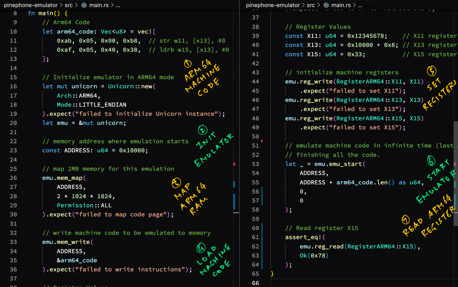
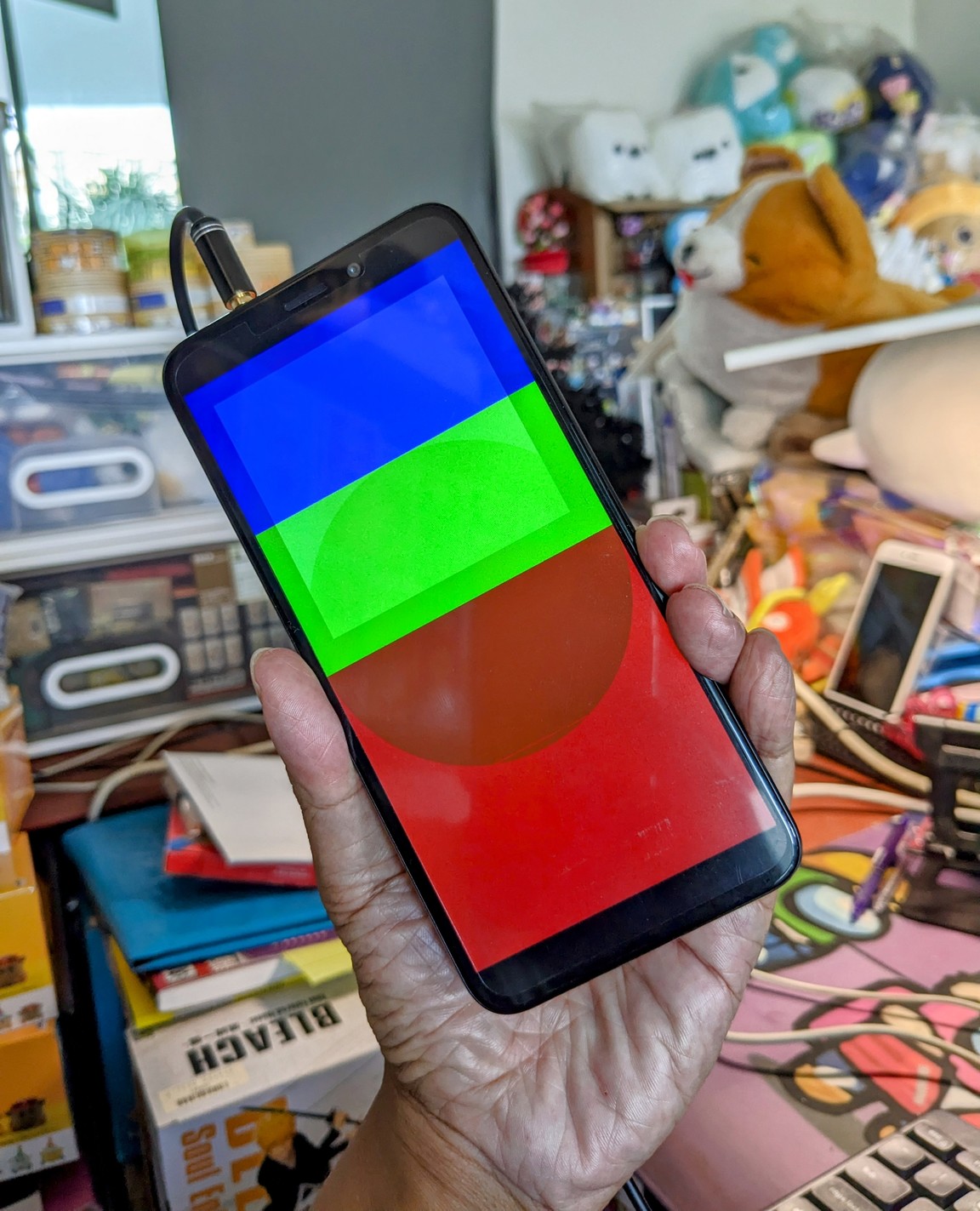
Read the articles...
We're now building a Feature Phone UI for NuttX on PinePhone...
Can we simulate the Feature Phone UI with Zig, LVGL and WebAssembly in a Web Browser? To make the UI Coding a little easier?
We have previously created a simple LVGL App with Zig for PinePhone...
Zig natively supports WebAssembly...
So we might run Zig + JavaScript in a Web Browser like so...
But LVGL doesn't work with JavaScript yet. LVGL runs in a Web Browser by compiling with Emscripten and SDL...
Therefore we shall do this...
-
Use Zig to compile LVGL from C to WebAssembly (With
zig cc) -
Use Zig to connect the JavaScript UI (canvas rendering + input events) to LVGL WebAssembly (Like this)
Check out the updates here...
TODO: WIP port of NuttX to PinePhone Pro
(1) Would be good to provide the Arm64 Disassembly.
(So that I can locate the addresses, also peek at the code snippets)
## Dump the disassembly to nuttx.S
aarch64-none-elf-objdump \
-t -S --demangle --line-numbers --wide \
nuttx \
>nuttx.S \
2>&1(2) What's the Boot Address kernel_addr_r for PinePhone Pro?
I can't find it in the docs, so I assume that this value is correct:
/* U-Boot loads NuttX at this address (kernel_addr_r) */
#define CONFIG_LOAD_BASE 0x02080000Here's how we get kernel_addr_r from U-Boot (is it the same for Tow-Boot?):
https://lupyuen.github.io/articles/uboot#boot-address
(3) Change the Memory Map (RAM and I/O) to this, based on the Address Mapping from RK3399 Tech Ref Manual (Part 1) Page 560:
https://github.com/apache/nuttx/blob/master/arch/arm64/include/a64/chip.h#L45-L51
// RAM Base Address: I'm guessing this based on CONFIG_LOAD_BASE (kernel_addr_r)
#define CONFIG_RAMBANK1_ADDR 0x02000000
// RAM Size: Let's keep this for now, we'll expand later
#define CONFIG_RAMBANK1_SIZE MB(512)
// I/O Addresses begin at F800_0000
#define CONFIG_DEVICEIO_BASEADDR 0xF8000000
// Up to FFFF_FFFF
#define CONFIG_DEVICEIO_SIZE MB(128)(4) Arm64 Generic Interrupt Controller (GIC) is Version 3 (instead of PinePhone's Version 2)
According to RK3399 Tech Ref Manual (Part 1) Page 560, RK3399 uses GIC-500, which is based on GIC v3. (PinePhone uses GIC v2)
To change GIC from v2 to v3:
make menuconfig
## Go to System Type > GIC version
## Change from 2 to 3
## Save and exit menuconfig
## Verify that GIC version is now 3:
grep ARM_GIC_VERSION .configMore about GIC: https://lupyuen.github.io/articles/interrupt#generic-interrupt-controller
More about ARM_GIC_VERSION: https://github.com/apache/nuttx/blob/master/arch/arm64/Kconfig#L200-L209
(5) Next we need to fill in the GIC Base Address:
https://github.com/apache/nuttx/blob/master/arch/arm64/include/a64/chip.h
/* Allwinner A64 Generic Interrupt Controller v2: Distributor and Redist */
#define CONFIG_GICD_BASE 0x1C81000
#define CONFIG_GICR_BASE 0x1C82000But GIC v3 requires an additional field CONFIG_GICR_OFFSET, like this code from NuttX QEMU:
https://github.com/apache/nuttx/blob/master/arch/arm64/include/qemu/chip.h#L47-L51
#define CONFIG_GICD_BASE 0x8000000
#define CONFIG_GICR_BASE 0x80a0000
#define CONFIG_GICR_OFFSET 0x20000According to the Linux Device Tree for RK3399:
- GICD = 0xfee00000
- GICR = 0xfef00000
But I'm not sure what's CONFIG_GICR_OFFSET. (Offset to the GIC Registers for each CPU?)
Maybe we stick with the current value and test whether UART Interrupts are OK?
RK3399 UART0 is at GIC Shared Peripheral Interrupt 99
RK3399 UART is a DesignWare APB UART (dw-apb-uart), which maps to the Linux DesignWare 8250 Driver (8250_dw.c).
Which is compatible with the NuttX 16550 UART Driver. So remember to enable 16550_WAIT_LCR, and set 16550_REGINCR=4. (Because regshift=2)
The IRQs (Interrupt IDs) might need to change:
https://github.com/apache/nuttx/blob/master/arch/arm64/include/a64/irq.h
This should follow RK3399 Tech Ref Manual (Part 1) Page 15.
Eventually the I/O Peripherals will have completely different addresses too:
https://github.com/apache/nuttx/blob/master/arch/arm64/src/a64/hardware/a64_memorymap.h
TODO
This section contains PinePhone NuttX Logs captured from various tests...
We captured this log of USB Devices on PinePhone, which will be helpful when we build the NuttX USB Driver for PinePhone's Quectel LTE Modem...
[manjaro@manjaro-arm ~]$ sudo lsusb -v
Bus 004 Device 001: ID 1d6b:0001 Linux Foundation 1.1 root hub
Device Descriptor:
bLength 18
bDescriptorType 1
bcdUSB 1.10
bDeviceClass 9 Hub
bDeviceSubClass 0
bDeviceProtocol 0 Full speed (or root) hub
bMaxPacketSize0 64
idVendor 0x1d6b Linux Foundation
idProduct 0x0001 1.1 root hub
bcdDevice 5.18
iManufacturer 3 Linux 5.18.9-1-MANJARO-ARM ohci_hcd
iProduct 2 Generic Platform OHCI controller
iSerial 1 1c1b400.usb
bNumConfigurations 1
Configuration Descriptor:
bLength 9
bDescriptorType 2
wTotalLength 0x0019
bNumInterfaces 1
bConfigurationValue 1
iConfiguration 0
bmAttributes 0xe0
Self Powered
Remote Wakeup
MaxPower 0mA
Interface Descriptor:
bLength 9
bDescriptorType 4
bInterfaceNumber 0
bAlternateSetting 0
bNumEndpoints 1
bInterfaceClass 9 Hub
bInterfaceSubClass 0
bInterfaceProtocol 0 Full speed (or root) hub
iInterface 0
Endpoint Descriptor:
bLength 7
bDescriptorType 5
bEndpointAddress 0x81 EP 1 IN
bmAttributes 3
Transfer Type Interrupt
Synch Type None
Usage Type Data
wMaxPacketSize 0x0002 1x 2 bytes
bInterval 255
Hub Descriptor:
bLength 9
bDescriptorType 41
nNbrPorts 1
wHubCharacteristic 0x000a
No power switching (usb 1.0)
Per-port overcurrent protection
bPwrOn2PwrGood 2 * 2 milli seconds
bHubContrCurrent 0 milli Ampere
DeviceRemovable 0x00
PortPwrCtrlMask 0xff
Hub Port Status:
Port 1: 0000.0100 power
Device Status: 0x0001
Self Powered
Bus 002 Device 002: ID 2c7c:0125 Quectel Wireless Solutions Co., Ltd. EC25 LTE modem
Device Descriptor:
bLength 18
bDescriptorType 1
bcdUSB 2.00
bDeviceClass 239 Miscellaneous Device
bDeviceSubClass 2
bDeviceProtocol 1 Interface Association
bMaxPacketSize0 64
idVendor 0x2c7c Quectel Wireless Solutions Co., Ltd.
idProduct 0x0125 EC25 LTE modem
bcdDevice 3.18
iManufacturer 1 Quectel
iProduct 2 EG25-G
iSerial 0
bNumConfigurations 1
Configuration Descriptor:
bLength 9
bDescriptorType 2
wTotalLength 0x00d1
bNumInterfaces 5
bConfigurationValue 1
iConfiguration 0
bmAttributes 0xa0
(Bus Powered)
Remote Wakeup
MaxPower 500mA
Interface Descriptor:
bLength 9
bDescriptorType 4
bInterfaceNumber 0
bAlternateSetting 0
bNumEndpoints 2
bInterfaceClass 255 Vendor Specific Class
bInterfaceSubClass 255 Vendor Specific Subclass
bInterfaceProtocol 255 Vendor Specific Protocol
iInterface 0
Endpoint Descriptor:
bLength 7
bDescriptorType 5
bEndpointAddress 0x81 EP 1 IN
bmAttributes 2
Transfer Type Bulk
Synch Type None
Usage Type Data
wMaxPacketSize 0x0200 1x 512 bytes
bInterval 0
Endpoint Descriptor:
bLength 7
bDescriptorType 5
bEndpointAddress 0x01 EP 1 OUT
bmAttributes 2
Transfer Type Bulk
Synch Type None
Usage Type Data
wMaxPacketSize 0x0200 1x 512 bytes
bInterval 0
Interface Descriptor:
bLength 9
bDescriptorType 4
bInterfaceNumber 1
bAlternateSetting 0
bNumEndpoints 3
bInterfaceClass 255 Vendor Specific Class
bInterfaceSubClass 0
bInterfaceProtocol 0
iInterface 0
** UNRECOGNIZED: 05 24 00 10 01
** UNRECOGNIZED: 05 24 01 00 00
** UNRECOGNIZED: 04 24 02 02
** UNRECOGNIZED: 05 24 06 00 00
Endpoint Descriptor:
bLength 7
bDescriptorType 5
bEndpointAddress 0x83 EP 3 IN
bmAttributes 3
Transfer Type Interrupt
Synch Type None
Usage Type Data
wMaxPacketSize 0x000a 1x 10 bytes
bInterval 9
Endpoint Descriptor:
bLength 7
bDescriptorType 5
bEndpointAddress 0x82 EP 2 IN
bmAttributes 2
Transfer Type Bulk
Synch Type None
Usage Type Data
wMaxPacketSize 0x0200 1x 512 bytes
bInterval 0
Endpoint Descriptor:
bLength 7
bDescriptorType 5
bEndpointAddress 0x02 EP 2 OUT
bmAttributes 2
Transfer Type Bulk
Synch Type None
Usage Type Data
wMaxPacketSize 0x0200 1x 512 bytes
bInterval 0
Interface Descriptor:
bLength 9
bDescriptorType 4
bInterfaceNumber 2
bAlternateSetting 0
bNumEndpoints 3
bInterfaceClass 255 Vendor Specific Class
bInterfaceSubClass 0
bInterfaceProtocol 0
iInterface 0
** UNRECOGNIZED: 05 24 00 10 01
** UNRECOGNIZED: 05 24 01 00 00
** UNRECOGNIZED: 04 24 02 02
** UNRECOGNIZED: 05 24 06 00 00
Endpoint Descriptor:
bLength 7
bDescriptorType 5
bEndpointAddress 0x85 EP 5 IN
bmAttributes 3
Transfer Type Interrupt
Synch Type None
Usage Type Data
wMaxPacketSize 0x000a 1x 10 bytes
bInterval 9
Endpoint Descriptor:
bLength 7
bDescriptorType 5
bEndpointAddress 0x84 EP 4 IN
bmAttributes 2
Transfer Type Bulk
Synch Type None
Usage Type Data
wMaxPacketSize 0x0200 1x 512 bytes
bInterval 0
Endpoint Descriptor:
bLength 7
bDescriptorType 5
bEndpointAddress 0x03 EP 3 OUT
bmAttributes 2
Transfer Type Bulk
Synch Type None
Usage Type Data
wMaxPacketSize 0x0200 1x 512 bytes
bInterval 0
Interface Descriptor:
bLength 9
bDescriptorType 4
bInterfaceNumber 3
bAlternateSetting 0
bNumEndpoints 3
bInterfaceClass 255 Vendor Specific Class
bInterfaceSubClass 0
bInterfaceProtocol 0
iInterface 0
** UNRECOGNIZED: 05 24 00 10 01
** UNRECOGNIZED: 05 24 01 00 00
** UNRECOGNIZED: 04 24 02 02
** UNRECOGNIZED: 05 24 06 00 00
Endpoint Descriptor:
bLength 7
bDescriptorType 5
bEndpointAddress 0x87 EP 7 IN
bmAttributes 3
Transfer Type Interrupt
Synch Type None
Usage Type Data
wMaxPacketSize 0x000a 1x 10 bytes
bInterval 9
Endpoint Descriptor:
bLength 7
bDescriptorType 5
bEndpointAddress 0x86 EP 6 IN
bmAttributes 2
Transfer Type Bulk
Synch Type None
Usage Type Data
wMaxPacketSize 0x0200 1x 512 bytes
bInterval 0
Endpoint Descriptor:
bLength 7
bDescriptorType 5
bEndpointAddress 0x04 EP 4 OUT
bmAttributes 2
Transfer Type Bulk
Synch Type None
Usage Type Data
wMaxPacketSize 0x0200 1x 512 bytes
bInterval 0
Interface Descriptor:
bLength 9
bDescriptorType 4
bInterfaceNumber 4
bAlternateSetting 0
bNumEndpoints 3
bInterfaceClass 255 Vendor Specific Class
bInterfaceSubClass 255 Vendor Specific Subclass
bInterfaceProtocol 255 Vendor Specific Protocol
iInterface 0
Endpoint Descriptor:
bLength 7
bDescriptorType 5
bEndpointAddress 0x89 EP 9 IN
bmAttributes 3
Transfer Type Interrupt
Synch Type None
Usage Type Data
wMaxPacketSize 0x0008 1x 8 bytes
bInterval 9
Endpoint Descriptor:
bLength 7
bDescriptorType 5
bEndpointAddress 0x88 EP 8 IN
bmAttributes 2
Transfer Type Bulk
Synch Type None
Usage Type Data
wMaxPacketSize 0x0200 1x 512 bytes
bInterval 0
Endpoint Descriptor:
bLength 7
bDescriptorType 5
bEndpointAddress 0x05 EP 5 OUT
bmAttributes 2
Transfer Type Bulk
Synch Type None
Usage Type Data
wMaxPacketSize 0x0200 1x 512 bytes
bInterval 0
Device Qualifier (for other device speed):
bLength 10
bDescriptorType 6
bcdUSB 2.00
bDeviceClass 239 Miscellaneous Device
bDeviceSubClass 2
bDeviceProtocol 1 Interface Association
bMaxPacketSize0 64
bNumConfigurations 1
Device Status: 0x0000
(Bus Powered)
Bus 002 Device 001: ID 1d6b:0002 Linux Foundation 2.0 root hub
Device Descriptor:
bLength 18
bDescriptorType 1
bcdUSB 2.00
bDeviceClass 9 Hub
bDeviceSubClass 0
bDeviceProtocol 0 Full speed (or root) hub
bMaxPacketSize0 64
idVendor 0x1d6b Linux Foundation
idProduct 0x0002 2.0 root hub
bcdDevice 5.18
iManufacturer 3 Linux 5.18.9-1-MANJARO-ARM ehci_hcd
iProduct 2 EHCI Host Controller
iSerial 1 1c1b000.usb
bNumConfigurations 1
Configuration Descriptor:
bLength 9
bDescriptorType 2
wTotalLength 0x0019
bNumInterfaces 1
bConfigurationValue 1
iConfiguration 0
bmAttributes 0xe0
Self Powered
Remote Wakeup
MaxPower 0mA
Interface Descriptor:
bLength 9
bDescriptorType 4
bInterfaceNumber 0
bAlternateSetting 0
bNumEndpoints 1
bInterfaceClass 9 Hub
bInterfaceSubClass 0
bInterfaceProtocol 0 Full speed (or root) hub
iInterface 0
Endpoint Descriptor:
bLength 7
bDescriptorType 5
bEndpointAddress 0x81 EP 1 IN
bmAttributes 3
Transfer Type Interrupt
Synch Type None
Usage Type Data
wMaxPacketSize 0x0004 1x 4 bytes
bInterval 12
Hub Descriptor:
bLength 9
bDescriptorType 41
nNbrPorts 1
wHubCharacteristic 0x000a
No power switching (usb 1.0)
Per-port overcurrent protection
bPwrOn2PwrGood 10 * 2 milli seconds
bHubContrCurrent 0 milli Ampere
DeviceRemovable 0x00
PortPwrCtrlMask 0xff
Hub Port Status:
Port 1: 0000.0503 highspeed power enable connect
Device Status: 0x0001
Self Powered
Bus 003 Device 001: ID 1d6b:0001 Linux Foundation 1.1 root hub
Device Descriptor:
bLength 18
bDescriptorType 1
bcdUSB 1.10
bDeviceClass 9 Hub
bDeviceSubClass 0
bDeviceProtocol 0 Full speed (or root) hub
bMaxPacketSize0 64
idVendor 0x1d6b Linux Foundation
idProduct 0x0001 1.1 root hub
bcdDevice 5.18
iManufacturer 3 Linux 5.18.9-1-MANJARO-ARM ohci_hcd
iProduct 2 Generic Platform OHCI controller
iSerial 1 1c1a400.usb
bNumConfigurations 1
Configuration Descriptor:
bLength 9
bDescriptorType 2
wTotalLength 0x0019
bNumInterfaces 1
bConfigurationValue 1
iConfiguration 0
bmAttributes 0xe0
Self Powered
Remote Wakeup
MaxPower 0mA
Interface Descriptor:
bLength 9
bDescriptorType 4
bInterfaceNumber 0
bAlternateSetting 0
bNumEndpoints 1
bInterfaceClass 9 Hub
bInterfaceSubClass 0
bInterfaceProtocol 0 Full speed (or root) hub
iInterface 0
Endpoint Descriptor:
bLength 7
bDescriptorType 5
bEndpointAddress 0x81 EP 1 IN
bmAttributes 3
Transfer Type Interrupt
Synch Type None
Usage Type Data
wMaxPacketSize 0x0002 1x 2 bytes
bInterval 255
Hub Descriptor:
bLength 9
bDescriptorType 41
nNbrPorts 1
wHubCharacteristic 0x000a
No power switching (usb 1.0)
Per-port overcurrent protection
bPwrOn2PwrGood 2 * 2 milli seconds
bHubContrCurrent 0 milli Ampere
DeviceRemovable 0x00
PortPwrCtrlMask 0xff
Hub Port Status:
Port 1: 0000.0100 power
Device Status: 0x0001
Self Powered
Bus 001 Device 001: ID 1d6b:0002 Linux Foundation 2.0 root hub
Device Descriptor:
bLength 18
bDescriptorType 1
bcdUSB 2.00
bDeviceClass 9 Hub
bDeviceSubClass 0
bDeviceProtocol 0 Full speed (or root) hub
bMaxPacketSize0 64
idVendor 0x1d6b Linux Foundation
idProduct 0x0002 2.0 root hub
bcdDevice 5.18
iManufacturer 3 Linux 5.18.9-1-MANJARO-ARM ehci_hcd
iProduct 2 EHCI Host Controller
iSerial 1 1c1a000.usb
bNumConfigurations 1
Configuration Descriptor:
bLength 9
bDescriptorType 2
wTotalLength 0x0019
bNumInterfaces 1
bConfigurationValue 1
iConfiguration 0
bmAttributes 0xe0
Self Powered
Remote Wakeup
MaxPower 0mA
Interface Descriptor:
bLength 9
bDescriptorType 4
bInterfaceNumber 0
bAlternateSetting 0
bNumEndpoints 1
bInterfaceClass 9 Hub
bInterfaceSubClass 0
bInterfaceProtocol 0 Full speed (or root) hub
iInterface 0
Endpoint Descriptor:
bLength 7
bDescriptorType 5
bEndpointAddress 0x81 EP 1 IN
bmAttributes 3
Transfer Type Interrupt
Synch Type None
Usage Type Data
wMaxPacketSize 0x0004 1x 4 bytes
bInterval 12
Hub Descriptor:
bLength 9
bDescriptorType 41
nNbrPorts 1
wHubCharacteristic 0x000a
No power switching (usb 1.0)
Per-port overcurrent protection
bPwrOn2PwrGood 10 * 2 milli seconds
bHubContrCurrent 0 milli Ampere
DeviceRemovable 0x00
PortPwrCtrlMask 0xff
Hub Port Status:
Port 1: 0000.0100 power
Device Status: 0x0001
Self Powered
PinePhone Test Log for the following Zig Drivers...
DRAM: 2048 MiB
Trying to boot from MMC1
NOTICE: BL31: v2.2(release):v2.2-904-gf9ea3a629
NOTICE: BL31: Built : 15:32:12, Apr 9 2020
NOTICE: BL31: Detected Allwinner A64/H64/R18 SoC (1689)
NOTICE: BL31: Found U-Boot DTB at 0x4064410, model: PinePhone
NOTICE: PSCI: System suspend is unavailable
U-Boot 2020.07 (Nov 08 2020 - 00:15:12 +0100)
DRAM: 2 GiB
MMC: Device 'mmc@1c11000': seq 1 is in use by 'mmc@1c10000'
mmc@1c0f000: 0, mmc@1c10000: 2, mmc@1c11000: 1
Loading Environment from FAT... *** Warning - bad CRC, using default environment
starting USB...
No working controllers found
Hit any key to stop autoboot: 0
switch to partitions #0, OK
mmc0 is current device
Scanning mmc 0:1...
Found U-Boot script /boot.scr
653 bytes read in 3 ms (211.9 KiB/s)
## Executing script at 4fc00000
gpio: pin 114 (gpio 114) value is 1
246286 bytes read in 14 ms (16.8 MiB/s)
Uncompressed size: 10465280 = 0x9FB000
36162 bytes read in 4 ms (8.6 MiB/s)
1078500 bytes read in 51 ms (20.2 MiB/s)
## Flattened Device Tree blob at 4fa00000
Booting using the fdt blob at 0x4fa00000
Loading Ramdisk to 49ef8000, end 49fff4e4 ... OK
Loading Device Tree to 0000000049eec000, end 0000000049ef7d41 ... OK
Starting kernel ...
HELLO NUTTX ON PINEPHONE!
- Ready to Boot CPU
- Boot from EL2
- Boot from EL1
- Boot to C runtime for OS Initialize
nx_start: Entry
up_allocate_heap: heap_start=0x0x40a7b000, heap_size=0x7585000
arm64_gic_initialize: TODO: Init GIC for PinePhone
arm64_gic_initialize: CONFIG_GICD_BASE=0x1c81000
arm64_gic_initialize: CONFIG_GICR_BASE=0x1c82000
arm64_gic_initialize: GIC Version is 2
up_timer_initialize: up_timer_initialize: cp15 timer(s) running at 24.00MHz, cycle 24000
up_timer_initialize: _vector_table=0x40100000
up_timer_initialize: Before writing: vbar_el1=0x40280000
up_timer_initialize: After writing: vbar_el1=0x40100000
uart_register: Registering /dev/console
uart_register: Registering /dev/ttyS0
work_start_highpri: Starting high-priority kernel worker thread(s)
nx_start_application: Starting init thread
lib_cxx_initialize: _sinit: 0x40100000 _einit: 0x40100000 _stext: 0x40080000 _etext: 0x40101000
nsh: sysinit: fopen failed: 2
nshn:x _msktfaarttf:s :C PcUo0m:m aBnedg innonti nfgo uInddl
e
L
oNoupt
t
Shell (NSH) NuttX-11.0.0-RC2
nsh>
nsh>
nsh> uname -a
NuttX 11.0.0-RC2 a33f82d Dec 2 2022 17:57:39 arm64 qemu-a53
nsh>
nsh> hello 3
task_spawn: name=hello entry=0x4009b4f8 file_actions=0x40a80580 attr=0x40a80588 argv=0x40a806d0
spawn_execattrs: Setting policy=2 priority=100 for pid=3
ABHello, World!!
pd_cfg2_reg=0x77711177
pd_data_reg=0x1c0000
test_render: start, channels=3
backlight_enable: start, percent=90
Configure PL10 for PWM
*0x1f02c04: clear 0x700, set 0x200
*0x1f02c04 = 0x77277
Disable R_PWM
*0x1f03800: clear 0x40, set 0x0
*0x1f03800 = 0x0
Configure R_PWM Period
*0x1f03804 = 0x4af0437
Enable R_PWM
*0x1f03800 = 0x5f
Configure PH10 for Output
*0x1c20900: clear 0x700, set 0x100
*0x1c20900 = 0x7177
Set PH10 to High
*0x1c2090c: clear 0x400, set 0x400
*0x1c2090c = 0x400
backlight_enable: end
tcon0_init: start
Configure PLL_VIDEO0
*0x1c20010 = 0x81006207
Enable LDO1 and LDO2
*0x1c20040 = 0xc00000
Configure MIPI PLL
*0x1c20040 = 0x80c0071a
Set TCON0 Clock Source to MIPI PLL
*0x1c20118 = 0x80000000
Enable TCON0 Clock
*0x1c20064 = 0x8
Deassert TCON0 Reset
*0x1c202c4 = 0x8
Disable TCON0 and Interrupts
*0x1c0c000 = 0x0
*0x1c0c004 = 0x0
*0x1c0c008 = 0x0
Enable Tristate Output
*0x1c0c08c = 0xffffffff
*0x1c0c0f4 = 0xffffffff
Set DCLK to MIPI PLL / 6
*0x1c0c044 = 0x80000006
*0x1c0c040 = 0x81000000
*0x1c0c048 = 0x2cf059f
*0x1c0c0f8 = 0x8
*0x1c0c060 = 0x10010005
Set CPU Panel Trigger
*0x1c0c160 = 0x2f02cf
*0x1c0c164 = 0x59f
*0x1c0c168 = 0x1bc2000a
Set Safe Period
*0x1c0c1f0 = 0xbb80003
Enable Output Triggers
*0x1c0c08c = 0xe0000000
Enable TCON0
*0x1c0c000: clear 0x80000000, set 0x80000000
*0x1c0c000 = 0x80000000
tcon0_init: end
display_board_init: start
Configure PD23 for Output
*0x1c20874: clear 0x70000000, set 0x10000000
*0x1c20874 = 0x17711177
Set PD23 to Low
*0x1c2087c: clear 0x800000, set 0x0
*0x1c2087c = 0x1c0000
Set DLDO1 Voltage to 3.3V
pmic_write: reg=0x15, val=0x1a
rsb_write: rt_addr=0x2d, reg_addr=0x15, value=0x1a
*0x1f0342c = 0x4e
*0x1f03430 = 0x2d0000
*0x1f03410 = 0x15
*0x1f0341c = 0x1a
*0x1f03400 = 0x80
pmic_clrsetbits: reg=0x12, clr_mask=0x0, set_mask=0x8
rsb_read: rt_addr=0x2d, reg_addr=0x12
*0x1f0342c = 0x8b
*0x1f03430 = 0x2d0000
*0x1f03410 = 0x12
*0x1f03400 = 0x80
rsb_write: rt_addr=0x2d, reg_addr=0x12, value=0xd9
*0x1f0342c = 0x4e
*0x1f03430 = 0x2d0000
*0x1f03410 = 0x12
*0x1f0341c = 0xd9
*0x1f03400 = 0x80
Set LDO Voltage to 3.3V
pmic_write: reg=0x91, val=0x1a
rsb_write: rt_addr=0x2d, reg_addr=0x91, value=0x1a
*0x1f0342c = 0x4e
*0x1f03430 = 0x2d0000
*0x1f03410 = 0x91
*0x1f0341c = 0x1a
*0x1f03400 = 0x80
Enable LDO mode on GPIO0
pmic_write: reg=0x90, val=0x3
rsb_write: rt_addr=0x2d, reg_addr=0x90, value=0x3
*0x1f0342c = 0x4e
*0x1f03430 = 0x2d0000
*0x1f03410 = 0x90
*0x1f0341c = 0x3
*0x1f03400 = 0x80
Set DLDO2 Voltage to 1.8V
pmic_write: reg=0x16, val=0xb
rsb_write: rt_addr=0x2d, reg_addr=0x16, value=0xb
*0x1f0342c = 0x4e
*0x1f03430 = 0x2d0000
*0x1f03410 = 0x16
*0x1f0341c = 0xb
*0x1f03400 = 0x80
pmic_clrsetbits: reg=0x12, clr_mask=0x0, set_mask=0x10
rsb_read: rt_addr=0x2d, reg_addr=0x12
*0x1f0342c = 0x8b
*0x1f03430 = 0x2d0000
*0x1f03410 = 0x12
*0x1f03400 = 0x80
rsb_write: rt_addr=0x2d, reg_addr=0x12, value=0xd9
*0x1f0342c = 0x4e
*0x1f03430 = 0x2d0000
*0x1f03410 = 0x12
*0x1f0341c = 0xd9
*0x1f03400 = 0x80
Wait for power supply and power-on init
display_board_init: end
enable_dsi_block: start
Enable MIPI DSI Bus
*0x1c20060: clear 0x2, set 0x2
*0x1c20060 = 0x4742
*0x1c202c0: clear 0x2, set 0x2
*0x1c202c0 = 0x4742
Enable DSI Block
*0x1ca0000 = 0x1
*0x1ca0010 = 0x30000
*0x1ca0060 = 0xa
*0x1ca0078 = 0x0
Set Instructions
*0x1ca0020 = 0x1f
*0x1ca0024 = 0x10000001
*0x1ca0028 = 0x20000010
*0x1ca002c = 0x2000000f
*0x1ca0030 = 0x30100001
*0x1ca0034 = 0x40000010
*0x1ca0038 = 0xf
*0x1ca003c = 0x5000001f
Configure Jump Instructions
*0x1ca004c = 0x560001
*0x1ca02f8 = 0xff
Set Video Start Delay
*0x1ca0014 = 0x5bc7
Set Burst
*0x1ca007c = 0x10000007
Set Instruction Loop
*0x1ca0040 = 0x30000002
*0x1ca0044 = 0x310031
*0x1ca0054 = 0x310031
Set Pixel Format
*0x1ca0090 = 0x1308703e
*0x1ca0098 = 0xffff
*0x1ca009c = 0xffffffff
*0x1ca0080 = 0x10008
Set Sync Timings
*0x1ca000c = 0x0
*0x1ca00b0 = 0x12000021
*0x1ca00b4 = 0x1000031
*0x1ca00b8 = 0x7000001
*0x1ca00bc = 0x14000011
Set Basic Size
*0x1ca0018 = 0x11000a
*0x1ca001c = 0x5cd05a0
Set Horizontal Blanking
*0x1ca00c0 = 0x9004a19
*0x1ca00c4 = 0x50b40000
*0x1ca00c8 = 0x35005419
*0x1ca00cc = 0x757a0000
*0x1ca00d0 = 0x9004a19
*0x1ca00d4 = 0x50b40000
*0x1ca00e0 = 0xc091a19
*0x1ca00e4 = 0x72bd0000
Set Vertical Blanking
*0x1ca00e8 = 0x1a000019
*0x1ca00ec = 0xffff0000
enable_dsi_block: end
dphy_enable: start
Set DSI Clock to 150 MHz
*0x1c20168 = 0x8203
Power on DPHY Tx
*0x1ca1004 = 0x10000000
*0x1ca1010 = 0xa06000e
*0x1ca1014 = 0xa033207
*0x1ca1018 = 0x1e
*0x1ca101c = 0x0
*0x1ca1020 = 0x303
Enable DPHY
*0x1ca1000 = 0x31
*0x1ca104c = 0x9f007f00
*0x1ca1050 = 0x17000000
*0x1ca105c = 0x1f01555
*0x1ca1054 = 0x2
Enable LDOR, LDOC, LDOD
*0x1ca1058 = 0x3040000
*0x1ca1058: clear 0xf8000000, set 0xf8000000
*0x1ca1058 = 0xfb040000
*0x1ca1058: clear 0x4000000, set 0x4000000
*0x1ca1058 = 0xff040000
*0x1ca1054: clear 0x10, set 0x10
*0x1ca1054 = 0x12
*0x1ca1050: clear 0x80000000, set 0x80000000
*0x1ca1050 = 0x97000000
*0x1ca1054: clear 0xf000000, set 0xf000000
*0x1ca1054 = 0xf000012
dphy_enable: end
panel_reset: start
Configure PD23 for Output
*0x1c20874: clear 0x70000000, set 0x10000000
*0x1c20874 = 0x17711177
Set PD23 to High
*0x1c2087c: clear 0x800000, set 0x800000
*0x1c2087c = 0x9c0000
wait for initialization
panel_reset: end
panel_init: start
writeDcs: len=4
b9 f1 12 83
mipi_dsi_dcs_write: channel=0, cmd=0x39, len=4
composeLongPacket: channel=0, cmd=0x39, len=4
packet: len=10
39 04 00 2c b9 f1 12 83
84 5d
*0x1ca0300: clear 0xffffffff, set 0x2c000439
*0x1ca0304: clear 0xffffffff, set 0x8312f1b9
*0x1ca0308: clear 0xffffffff, set 0x5d84
*0x1ca0200: clear 0xff, set 0x9
*0x1ca0010: clear 0x1, set 0x0
*0x1ca0010: clear 0x1, set 0x1
writeDcs: len=28
ba 33 81 05 f9 0e 0e 20
00 00 00 00 00 00 00 44
25 00 91 0a 00 00 02 4f
11 00 00 37
mipi_dsi_dcs_write: channel=0, cmd=0x39, len=28
composeLongPacket: channel=0, cmd=0x39, len=28
packet: len=34
39 1c 00 2f ba 33 81 05
f9 0e 0e 20 00 00 00 00
00 00 00 44 25 00 91 0a
00 00 02 4f 11 00 00 37
2c e2
*0x1ca0300: clear 0xffffffff, set 0x2f001c39
*0x1ca0304: clear 0xffffffff, set 0x58133ba
*0x1ca0308: clear 0xffffffff, set 0x200e0ef9
*0x1ca030c: clear 0xffffffff, set 0x0
*0x1ca0310: clear 0xffffffff, set 0x44000000
*0x1ca0314: clear 0xffffffff, set 0xa910025
*0x1ca0318: clear 0xffffffff, set 0x4f020000
*0x1ca031c: clear 0xffffffff, set 0x37000011
*0x1ca0320: clear 0xffffffff, set 0xe22c
*0x1ca0200: clear 0xff, set 0x21
*0x1ca0010: clear 0x1, set 0x0
*0x1ca0010: clear 0x1, set 0x1
writeDcs: len=5
b8 25 22 20 03
mipi_dsi_dcs_write: channel=0, cmd=0x39, len=5
composeLongPacket: channel=0, cmd=0x39, len=5
packet: len=11
39 05 00 36 b8 25 22 20
03 03 72
*0x1ca0300: clear 0xffffffff, set 0x36000539
*0x1ca0304: clear 0xffffffff, set 0x202225b8
*0x1ca0308: clear 0xffffffff, set 0x720303
*0x1ca0200: clear 0xff, set 0xa
*0x1ca0010: clear 0x1, set 0x0
*0x1ca0010: clear 0x1, set 0x1
writeDcs: len=11
b3 10 10 05 05 03 ff 00
00 00 00
mipi_dsi_dcs_write: channel=0, cmd=0x39, len=11
composeLongPacket: channel=0, cmd=0x39, len=11
packet: len=17
39 0b 00 2c b3 10 10 05
05 03 ff 00 00 00 00 6f
bc
*0x1ca0300: clear 0xffffffff, set 0x2c000b39
*0x1ca0304: clear 0xffffffff, set 0x51010b3
*0x1ca0308: clear 0xffffffff, set 0xff0305
*0x1ca030c: clear 0xffffffff, set 0x6f000000
*0x1ca0310: clear 0xffffffff, set 0xbc
*0x1ca0200: clear 0xff, set 0x10
*0x1ca0010: clear 0x1, set 0x0
*0x1ca0010: clear 0x1, set 0x1
writeDcs: len=10
c0 73 73 50 50 00 c0 08
70 00
mipi_dsi_dcs_write: channel=0, cmd=0x39, len=10
composeLongPacket: channel=0, cmd=0x39, len=10
packet: len=16
39 0a 00 36 c0 73 73 50
50 00 c0 08 70 00 1b 6a
*0x1ca0300: clear 0xffffffff, set 0x36000a39
*0x1ca0304: clear 0xffffffff, set 0x507373c0
*0x1ca0308: clear 0xffffffff, set 0x8c00050
*0x1ca030c: clear 0xffffffff, set 0x6a1b0070
*0x1ca0200: clear 0xff, set 0xf
*0x1ca0010: clear 0x1, set 0x0
*0x1ca0010: clear 0x1, set 0x1
writeDcs: len=2
bc 4e
mipi_dsi_dcs_write: channel=0, cmd=0x15, len=2
composeShortPacket: channel=0, cmd=0x15, len=2
packet: len=4
15 bc 4e 35
*0x1ca0300: clear 0xffffffff, set 0x354ebc15
*0x1ca0200: clear 0xff, set 0x3
*0x1ca0010: clear 0x1, set 0x0
*0x1ca0010: clear 0x1, set 0x1
writeDcs: len=2
cc 0b
mipi_dsi_dcs_write: channel=0, cmd=0x15, len=2
composeShortPacket: channel=0, cmd=0x15, len=2
packet: len=4
15 cc 0b 22
*0x1ca0300: clear 0xffffffff, set 0x220bcc15
*0x1ca0200: clear 0xff, set 0x3
*0x1ca0010: clear 0x1, set 0x0
*0x1ca0010: clear 0x1, set 0x1
writeDcs: len=2
b4 80
mipi_dsi_dcs_write: channel=0, cmd=0x15, len=2
composeShortPacket: channel=0, cmd=0x15, len=2
packet: len=4
15 b4 80 22
*0x1ca0300: clear 0xffffffff, set 0x2280b415
*0x1ca0200: clear 0xff, set 0x3
*0x1ca0010: clear 0x1, set 0x0
*0x1ca0010: clear 0x1, set 0x1
writeDcs: len=4
b2 f0 12 f0
mipi_dsi_dcs_write: channel=0, cmd=0x39, len=4
composeLongPacket: channel=0, cmd=0x39, len=4
packet: len=10
39 04 00 2c b2 f0 12 f0
51 86
*0x1ca0300: clear 0xffffffff, set 0x2c000439
*0x1ca0304: clear 0xffffffff, set 0xf012f0b2
*0x1ca0308: clear 0xffffffff, set 0x8651
*0x1ca0200: clear 0xff, set 0x9
*0x1ca0010: clear 0x1, set 0x0
*0x1ca0010: clear 0x1, set 0x1
writeDcs: len=15
e3 00 00 0b 0b 10 10 00
00 00 00 ff 00 c0 10
mipi_dsi_dcs_write: channel=0, cmd=0x39, len=15
composeLongPacket: channel=0, cmd=0x39, len=15
packet: len=21
39 0f 00 0f e3 00 00 0b
0b 10 10 00 00 00 00 ff
00 c0 10 36 0f
*0x1ca0300: clear 0xffffffff, set 0xf000f39
*0x1ca0304: clear 0xffffffff, set 0xb0000e3
*0x1ca0308: clear 0xffffffff, set 0x10100b
*0x1ca030c: clear 0xffffffff, set 0xff000000
*0x1ca0310: clear 0xffffffff, set 0x3610c000
*0x1ca0314: clear 0xffffffff, set 0xf
*0x1ca0200: clear 0xff, set 0x14
*0x1ca0010: clear 0x1, set 0x0
*0x1ca0010: clear 0x1, set 0x1
writeDcs: len=6
c6 01 00 ff ff 00
mipi_dsi_dcs_write: channel=0, cmd=0x39, len=6
composeLongPacket: channel=0, cmd=0x39, len=6
packet: len=12
39 06 00 30 c6 01 00 ff
ff 00 8e 25
*0x1ca0300: clear 0xffffffff, set 0x30000639
*0x1ca0304: clear 0xffffffff, set 0xff0001c6
*0x1ca0308: clear 0xffffffff, set 0x258e00ff
*0x1ca0200: clear 0xff, set 0xb
*0x1ca0010: clear 0x1, set 0x0
*0x1ca0010: clear 0x1, set 0x1
writeDcs: len=13
c1 74 00 32 32 77 f1 ff
ff cc cc 77 77
mipi_dsi_dcs_write: channel=0, cmd=0x39, len=13
composeLongPacket: channel=0, cmd=0x39, len=13
packet: len=19
39 0d 00 13 c1 74 00 32
32 77 f1 ff ff cc cc 77
77 69 e4
*0x1ca0300: clear 0xffffffff, set 0x13000d39
*0x1ca0304: clear 0xffffffff, set 0x320074c1
*0x1ca0308: clear 0xffffffff, set 0xfff17732
*0x1ca030c: clear 0xffffffff, set 0x77ccccff
*0x1ca0310: clear 0xffffffff, set 0xe46977
*0x1ca0200: clear 0xff, set 0x12
*0x1ca0010: clear 0x1, set 0x0
*0x1ca0010: clear 0x1, set 0x1
writeDcs: len=3
b5 07 07
mipi_dsi_dcs_write: channel=0, cmd=0x39, len=3
composeLongPacket: channel=0, cmd=0x39, len=3
packet: len=9
39 03 00 09 b5 07 07 7b
b3
*0x1ca0300: clear 0xffffffff, set 0x9000339
*0x1ca0304: clear 0xffffffff, set 0x7b0707b5
*0x1ca0308: clear 0xffffffff, set 0xb3
*0x1ca0200: clear 0xff, set 0x8
*0x1ca0010: clear 0x1, set 0x0
*0x1ca0010: clear 0x1, set 0x1
writeDcs: len=3
b6 2c 2c
mipi_dsi_dcs_write: channel=0, cmd=0x39, len=3
composeLongPacket: channel=0, cmd=0x39, len=3
packet: len=9
39 03 00 09 b6 2c 2c 55
04
*0x1ca0300: clear 0xffffffff, set 0x9000339
*0x1ca0304: clear 0xffffffff, set 0x552c2cb6
*0x1ca0308: clear 0xffffffff, set 0x4
*0x1ca0200: clear 0xff, set 0x8
*0x1ca0010: clear 0x1, set 0x0
*0x1ca0010: clear 0x1, set 0x1
writeDcs: len=4
bf 02 11 00
mipi_dsi_dcs_write: channel=0, cmd=0x39, len=4
composeLongPacket: channel=0, cmd=0x39, len=4
packet: len=10
39 04 00 2c bf 02 11 00
b5 e9
*0x1ca0300: clear 0xffffffff, set 0x2c000439
*0x1ca0304: clear 0xffffffff, set 0x1102bf
*0x1ca0308: clear 0xffffffff, set 0xe9b5
*0x1ca0200: clear 0xff, set 0x9
*0x1ca0010: clear 0x1, set 0x0
*0x1ca0010: clear 0x1, set 0x1
writeDcs: len=64
e9 82 10 06 05 a2 0a a5
12 31 23 37 83 04 bc 27
38 0c 00 03 00 00 00 0c
00 03 00 00 00 75 75 31
88 88 88 88 88 88 13 88
64 64 20 88 88 88 88 88
88 02 88 00 00 00 00 00
00 00 00 00 00 00 00 00
mipi_dsi_dcs_write: channel=0, cmd=0x39, len=64
composeLongPacket: channel=0, cmd=0x39, len=64
packet: len=70
39 40 00 25 e9 82 10 06
05 a2 0a a5 12 31 23 37
83 04 bc 27 38 0c 00 03
00 00 00 0c 00 03 00 00
00 75 75 31 88 88 88 88
88 88 13 88 64 64 20 88
88 88 88 88 88 02 88 00
00 00 00 00 00 00 00 00
00 00 00 00 65 03
*0x1ca0300: clear 0xffffffff, set 0x25004039
*0x1ca0304: clear 0xffffffff, set 0x61082e9
*0x1ca0308: clear 0xffffffff, set 0xa50aa205
*0x1ca030c: clear 0xffffffff, set 0x37233112
*0x1ca0310: clear 0xffffffff, set 0x27bc0483
*0x1ca0314: clear 0xffffffff, set 0x3000c38
*0x1ca0318: clear 0xffffffff, set 0xc000000
*0x1ca031c: clear 0xffffffff, set 0x300
*0x1ca0320: clear 0xffffffff, set 0x31757500
*0x1ca0324: clear 0xffffffff, set 0x88888888
*0x1ca0328: clear 0xffffffff, set 0x88138888
*0x1ca032c: clear 0xffffffff, set 0x88206464
*0x1ca0330: clear 0xffffffff, set 0x88888888
*0x1ca0334: clear 0xffffffff, set 0x880288
*0x1ca0338: clear 0xffffffff, set 0x0
*0x1ca033c: clear 0xffffffff, set 0x0
*0x1ca0340: clear 0xffffffff, set 0x0
*0x1ca0344: clear 0xffffffff, set 0x365
*0x1ca0200: clear 0xff, set 0x45
*0x1ca0010: clear 0x1, set 0x0
*0x1ca0010: clear 0x1, set 0x1
writeDcs: len=62
ea 02 21 00 00 00 00 00
00 00 00 00 00 02 46 02
88 88 88 88 88 88 64 88
13 57 13 88 88 88 88 88
88 75 88 23 14 00 00 02
00 00 00 00 00 00 00 00
00 00 00 00 00 00 00 03
0a a5 00 00 00 00
mipi_dsi_dcs_write: channel=0, cmd=0x39, len=62
composeLongPacket: channel=0, cmd=0x39, len=62
packet: len=68
39 3e 00 1a ea 02 21 00
00 00 00 00 00 00 00 00
00 02 46 02 88 88 88 88
88 88 64 88 13 57 13 88
88 88 88 88 88 75 88 23
14 00 00 02 00 00 00 00
00 00 00 00 00 00 00 00
00 00 00 03 0a a5 00 00
00 00 24 1b
*0x1ca0300: clear 0xffffffff, set 0x1a003e39
*0x1ca0304: clear 0xffffffff, set 0x2102ea
*0x1ca0308: clear 0xffffffff, set 0x0
*0x1ca030c: clear 0xffffffff, set 0x0
*0x1ca0310: clear 0xffffffff, set 0x2460200
*0x1ca0314: clear 0xffffffff, set 0x88888888
*0x1ca0318: clear 0xffffffff, set 0x88648888
*0x1ca031c: clear 0xffffffff, set 0x88135713
*0x1ca0320: clear 0xffffffff, set 0x88888888
*0x1ca0324: clear 0xffffffff, set 0x23887588
*0x1ca0328: clear 0xffffffff, set 0x2000014
*0x1ca032c: clear 0xffffffff, set 0x0
*0x1ca0330: clear 0xffffffff, set 0x0
*0x1ca0334: clear 0xffffffff, set 0x0
*0x1ca0338: clear 0xffffffff, set 0x3000000
*0x1ca033c: clear 0xffffffff, set 0xa50a
*0x1ca0340: clear 0xffffffff, set 0x1b240000
*0x1ca0200: clear 0xff, set 0x43
*0x1ca0010: clear 0x1, set 0x0
*0x1ca0010: clear 0x1, set 0x1
writeDcs: len=35
e0 00 09 0d 23 27 3c 41
35 07 0d 0e 12 13 10 12
12 18 00 09 0d 23 27 3c
41 35 07 0d 0e 12 13 10
12 12 18
mipi_dsi_dcs_write: channel=0, cmd=0x39, len=35
composeLongPacket: channel=0, cmd=0x39, len=35
packet: len=41
39 23 00 20 e0 00 09 0d
23 27 3c 41 35 07 0d 0e
12 13 10 12 12 18 00 09
0d 23 27 3c 41 35 07 0d
0e 12 13 10 12 12 18 93
bf
*0x1ca0300: clear 0xffffffff, set 0x20002339
*0x1ca0304: clear 0xffffffff, set 0xd0900e0
*0x1ca0308: clear 0xffffffff, set 0x413c2723
*0x1ca030c: clear 0xffffffff, set 0xe0d0735
*0x1ca0310: clear 0xffffffff, set 0x12101312
*0x1ca0314: clear 0xffffffff, set 0x9001812
*0x1ca0318: clear 0xffffffff, set 0x3c27230d
*0x1ca031c: clear 0xffffffff, set 0xd073541
*0x1ca0320: clear 0xffffffff, set 0x1013120e
*0x1ca0324: clear 0xffffffff, set 0x93181212
*0x1ca0328: clear 0xffffffff, set 0xbf
*0x1ca0200: clear 0xff, set 0x28
*0x1ca0010: clear 0x1, set 0x0
*0x1ca0010: clear 0x1, set 0x1
writeDcs: len=1
11
mipi_dsi_dcs_write: channel=0, cmd=0x5, len=1
composeShortPacket: channel=0, cmd=0x5, len=1
packet: len=4
05 11 00 36
*0x1ca0300: clear 0xffffffff, set 0x36001105
*0x1ca0200: clear 0xff, set 0x3
*0x1ca0010: clear 0x1, set 0x0
*0x1ca0010: clear 0x1, set 0x1
writeDcs: len=1
29
mipi_dsi_dcs_write: channel=0, cmd=0x5, len=1
composeShortPacket: channel=0, cmd=0x5, len=1
packet: len=4
05 29 00 1c
*0x1ca0300: clear 0xffffffff, set 0x1c002905
*0x1ca0200: clear 0xff, set 0x3
*0x1ca0010: clear 0x1, set 0x0
*0x1ca0010: clear 0x1, set 0x1
panel_init: end
start_dsi: start
Start HSC
*0x1ca0048 = 0xf02
Commit
*0x1ca0010: clear 0x1, set 0x1
*0x1ca0010 = 0x30001
Instruction Function Lane
*0x1ca0020: clear 0x10, set 0x0
*0x1ca0020 = 0xf
Start HSD
*0x1ca0048 = 0x63f07006
Commit
*0x1ca0010: clear 0x1, set 0x1
*0x1ca0010 = 0x30001
start_dsi: end
de2_init: start
Set High Speed SRAM to DMA Mode
*0x1c00004 = 0x0
Set Display Engine PLL to 297 MHz
*0x1c20048 = 0x81001701
Wait for Display Engine PLL to be stable
Set Special Clock to Display Engine PLL
*0x1c20104: clear 0x87000000, set 0x81000000
*0x1c20104 = 0x81000000
Enable AHB for Display Engine: De-Assert Display Engine
*0x1c202c4: clear 0x1000, set 0x1000
*0x1c202c4 = 0x1008
Enable AHB for Display Engine: Pass Display Engine
*0x1c20064: clear 0x1000, set 0x1000
*0x1c20064 = 0x1008
Enable Clock for MIXER0: SCLK Clock Pass
*0x1000000: clear 0x1, set 0x1
*0x1000000 = 0x1
Enable Clock for MIXER0: HCLK Clock Reset Off
*0x1000008: clear 0x1, set 0x1
*0x1000008 = 0x1
Enable Clock for MIXER0: HCLK Clock Pass
*0x1000004: clear 0x1, set 0x1
*0x1000004 = 0x1
Route MIXER0 to TCON0
*0x1000010: clear 0x1, set 0x0
*0x1000010 = 0x0
Clear MIXER0 Registers: GLB, BLD, OVL_V, OVL_UI
*0x1100000 = 0x0
to *0x1105fff = 0x0
Disable MIXER0 VSU
*0x1120000 = 0x0
Disable MIXER0 Undocumented
*0x1130000 = 0x0
Disable MIXER0 UI_SCALER1
*0x1140000 = 0x0
Disable MIXER0 UI_SCALER2
*0x1150000 = 0x0
Disable MIXER0 FCE
*0x11a0000 = 0x0
Disable MIXER0 BWS
*0x11a2000 = 0x0
Disable MIXER0 LTI
*0x11a4000 = 0x0
Disable MIXER0 PEAKING
*0x11a6000 = 0x0
Disable MIXER0 ASE
*0x11a8000 = 0x0
Disable MIXER0 FCC
*0x11aa000 = 0x0
Disable MIXER0 DRC
*0x11b0000 = 0x0
Enable MIXER0
*0x1100000 = 0x1
de2_init: end
renderGraphics: start
initUiBlender: start
Set Blender Background
*0x1101088 = 0xff000000
Set Blender Pre-Multiply
*0x1101084 = 0x0
initUiBlender: end
initUiChannel: start
Channel 1: Set Overlay (720 x 1440)
*0x1103000 = 0xff000405
*0x1103010 = 0x4012c000
*0x110300c = 0xb40
*0x1103004 = 0x59f02cf
*0x1103088 = 0x59f02cf
*0x1103008 = 0x0
Channel 1: Set Blender Output
*0x110108c = 0x59f02cf
*0x110000c = 0x59f02cf
Channel 1: Set Blender Input Pipe 0 (720 x 1440)
*0x1101008 = 0x59f02cf
*0x1101004 = 0xff000000
*0x110100c = 0x0
*0x1101090 = 0x3010301
Channel 1: Disable Scaler
*0x1140000 = 0x0
initUiChannel: end
initUiChannel: start
Channel 2: Set Overlay (600 x 600)
*0x1104000 = 0xff000005
*0x1104010 = 0x40521000
*0x110400c = 0x960
*0x1104004 = 0x2570257
*0x1104088 = 0x2570257
*0x1104008 = 0x0
Channel 2: Set Blender Input Pipe 1 (600 x 600)
*0x1101018 = 0x2570257
*0x1101014 = 0xff000000
*0x110101c = 0x340034
*0x1101094 = 0x3010301
Channel 2: Disable Scaler
*0x1150000 = 0x0
initUiChannel: end
initUiChannel: start
Channel 3: Set Overlay (720 x 1440)
*0x1105000 = 0x7f000005
*0x1105010 = 0x40681000
*0x110500c = 0xb40
*0x1105004 = 0x59f02cf
*0x1105088 = 0x59f02cf
*0x1105008 = 0x0
Channel 3: Set Blender Input Pipe 2 (720 x 1440)
*0x1101028 = 0x59f02cf
*0x1101024 = 0xff000000
*0x110102c = 0x0
*0x1101098 = 0x3010301
Channel 3: Disable Scaler
*0x1160000 = 0x0
initUiChannel: end
applySettings: start
Set Blender Route
*0x1101080 = 0x321
Enable Blender Pipes
*0x1101000 = 0x701
Apply Settings
*0x1100008 = 0x1
applySettings: end
renderGraphics: end
test_render: end
HELLO ZIG ON PINEPHONE!
test_zig: start
Testing Compose Short Packet (Without Parameter)...
composeShortPacket: channel=0, cmd=0x5, len=1
Result:
05 11 00 36
Testing Compose Short Packet (With Parameter)...
composeShortPacket: channel=0, cmd=0x15, len=2
Result:
15 bc 4e 35
Testing Compose Long Packet...
composeLongPacket: channel=0, cmd=0x39, len=64
Result:
39 40 00 25 e9 82 10 06
05 a2 0a a5 12 31 23 37
83 04 bc 27 38 0c 00 03
00 00 00 0c 00 03 00 00
00 75 75 31 88 88 88 88
88 88 13 88 64 64 20 88
88 88 88 88 88 02 88 00
00 00 00 00 00 00 00 00
00 00 00 00 65 03
test_zig: end
nsh>
nsh>
DRAM: 2048 MiB
Trying to boot from MMC1
NOTICE: BL31: v2.2(release):v2.2-904-gf9ea3a629
NOTICE: BL31: Built : 15:32:12, Apr 9 2020
NOTICE: BL31: Detected Allwinner A64/H64/R18 SoC (1689)
NOTICE: BL31: Found U-Boot DTB at 0x4064410, model: PinePhone
NOTICE: PSCI: System suspend is unavailable
U-Boot 2020.07 (Nov 08 2020 - 00:15:12 +0100)
DRAM: 2 GiB
MMC: Device 'mmc@1c11000': seq 1 is in use by 'mmc@1c10000'
mmc@1c0f000: 0, mmc@1c10000: 2, mmc@1c11000: 1
Loading Environment from FAT... *** Warning - bad CRC, using default environment
starting USB...
No working controllers found
Hit any key to stop autoboot: 0
switch to partitions #0, OK
mmc0 is current device
Scanning mmc 0:1...
Found U-Boot script /boot.scr
653 bytes read in 3 ms (211.9 KiB/s)
## Executing script at 4fc00000
gpio: pin 114 (gpio 114) value is 1
220236 bytes read in 14 ms (15 MiB/s)
Uncompressed size: 10268672 = 0x9CB000
36162 bytes read in 5 ms (6.9 MiB/s)
1078500 bytes read in 50 ms (20.6 MiB/s)
## Flattened Device Tree blob at 4fa00000
Booting using the fdt blob at 0x4fa00000
Loading Ramdisk to 49ef8000, end 49fff4e4 ... OK
Loading Device Tree to 0000000049eec000, end 0000000049ef7d41 ... OK
Starting kernel ...
HELLO NUTTX ON PINEPHONE!
- Ready to Boot CPU
- Boot from EL2
- Boot from EL1
- Boot to C runtime for OS Initialize
nx_start: Entry
up_allocate_heap: heap_start=0x0x40a4b000, heap_size=0x75b5000
arm64_gic_initialize: TODO: Init GIC for PinePhone
arm64_gic_initialize: CONFIG_GICD_BASE=0x1c81000
arm64_gic_initialize: CONFIG_GICR_BASE=0x1c82000
arm64_gic_initialize: GIC Version is 2
up_timer_initialize: up_timer_initialize: cp15 timer(s) running at 24.00MHz, cycle 24000
up_timer_initialize: _vector_table=0x400d7000
up_timer_initialize: Before writing: vbar_el1=0x40257000
up_timer_initialize: After writing: vbar_el1=0x400d7000
uart_register: Registering /dev/console
uart_register: Registering /dev/ttyS0
work_start_highpri: Starting high-priority kernel worker thread(s)
nx_start_application: Starting init thread
lib_cxx_initialize: _sinit: 0x400d7000 _einit: 0x400d7000 _stext: 0x40080000 _etext: 0x400d8000
nsh: sysinit: fopen failed: 2
nshn:x _msktfaarttf:s :C PcUo0m:m aBnedg innonti nfgo uInddl
e
L
oNoupt
t
Shell (NSH) NuttX-11.0.0-RC2
nsh> hello
task_spawn: name=hello entry=0x4009d490 file_actions=0x40a50580 attr=0x40a50588 argv=0x40a506d0
spawn_execattrs: Setting policy=2 priority=100 for pid=3
ABHello, World!!
ph_cfg1_reg=0x7177
ph_data_reg=0x400
pd_cfg2_reg=0x77711177
pd_data_reg=0x1c0000
tcon0_init: start
PLL_VIDEO0
0x1c20010 = 0x81006207 (DMB)
PLL_MIPI
0x1c20040 = 0xc00000 (DMB)
udelay 100
0x1c20040 = 0x80c0071a (DMB)
TCON0 source MIPI_PLL
0x1c20118 = 0x80000000 (DMB)
Clock on
0x1c20064 = 0x8 (DMB)
Reset off
0x1c202c4 = 0x8 (DMB)
Init lcdc: Disable tcon, Disable all interrupts
0x1c0c000 = 0x0 (DMB)
0x1c0c004 = 0x0
0x1c0c008 = 0x0
Set all io lines to tristate
0x1c0c08c = 0xffffffff
0x1c0c0f4 = 0xffffffff
mode set: DCLK = MIPI_PLL / 6
0x1c0c044 = 0x80000006
0x1c0c040 = 0x81000000
0x1c0c048 = 0x2cf059f
0x1c0c0f8 = 0x8
0x1c0c060 = 0x10010005
The datasheet says that this should be set higher than 20 * pixel cycle, but it's not clear what a pixel cycle is.
0x1c0c160 = 0x2f02cf
0x1c0c164 = 0x59f
0x1c0c168 = 0x1bc2000a
The Allwinner BSP has a comment that the period should be the display clock * 15, but uses an hardcoded 3000
0x1c0c1f0 = 0xbb80003
Enable the output on the pins
0x1c0c08c = 0xe0000000 (DMB)
enable tcon as a whole
setbits 0x1c0c000, 0x80000000 (DMB)
tcon0_init: end
dsi_init: start
display_board_init: start
assert reset: GPD(23), 0 // PD23 - LCD-RST (active low)
sunxi_gpio_set_cfgpin: pin=0x77, val=1
sunxi_gpio_set_cfgbank: bank_offset=119, val=1
clrsetbits 0x1c20874, 0xf0000000, 0x10000000
sunxi_gpio_output: pin=0x77, val=0
before: 0x1c2087c = 0x1c0000
after: 0x1c2087c = 0x1c0000 (DMB)
dldo1 3.3V
pmic_write: reg=0x15, val=0x1a
rsb_write: rt_addr=0x2d, reg_addr=0x15, value=0x1a
pmic_clrsetbits: reg=0x12, clr_mask=0x0, set_mask=0x8
rsb_read: rt_addr=0x2d, reg_addr=0x12
rsb_write: rt_addr=0x2d, reg_addr=0x12, value=0xd9
ldo_io0 3.3V
pmic_write: reg=0x91, val=0x1a
rsb_write: rt_addr=0x2d, reg_addr=0x91, value=0x1a
pmic_write: reg=0x90, val=0x3
rsb_write: rt_addr=0x2d, reg_addr=0x90, value=0x3
dldo2 1.8V
pmic_write: reg=0x16, val=0xb
rsb_write: rt_addr=0x2d, reg_addr=0x16, value=0xb
pmic_clrsetbits: reg=0x12, clr_mask=0x0, set_mask=0x10
rsb_read: rt_addr=0x2d, reg_addr=0x12
rsb_write: rt_addr=0x2d, reg_addr=0x12, value=0xd9
wait for power supplies and power-on init
udelay 15000
display_board_init: end
mipi dsi bus enable
setbits 0x1c20060, 0x2 (DMB)
setbits 0x1c202c0, 0x2 (DMB)
Enable the DSI block
struct reg_inst dsi_init_seq[] = {
.{ 0x0000, 0x00000001 }, // DMB
.{ 0x0010, 0x00030000 }, // DMB
.{ 0x0060, 0x0000000a }, // DMB
.{ 0x0078, 0x00000000 }, // DMB
inst_init
.{ 0x0020, 0x0000001f }, // DMB
.{ 0x0024, 0x10000001 }, // DMB
.{ 0x0028, 0x20000010 }, // DMB
.{ 0x002c, 0x2000000f }, // DMB
.{ 0x0030, 0x30100001 }, // DMB
.{ 0x0034, 0x40000010 }, // DMB
.{ 0x0038, 0x0000000f }, // DMB
.{ 0x003c, 0x5000001f }, // DMB
.{ 0x004c, 0x00560001 }, // DMB
.{ 0x02f8, 0x000000ff }, // DMB
get_video_start_delay
.{ 0x0014, 0x00005bc7 }, // DMB
setup_burst
.{ 0x007c, 0x10000007 }, // DMB
setup_inst_loop
.{ 0x0040, 0x30000002 }, // DMB
.{ 0x0044, 0x00310031 }, // DMB
.{ 0x0054, 0x00310031 }, // DMB
setup_format
.{ 0x0090, 0x1308703e }, // DMB
.{ 0x0098, 0x0000ffff }, // DMB
.{ 0x009c, 0xffffffff }, // DMB
.{ 0x0080, 0x00010008 }, // DMB
setup_timings
display_malloc: size=2330
.{ 0x000c, 0x00000000 }, // DMB
.{ 0x00b0, 0x12000021 }, // DMB
.{ 0x00b4, 0x01000031 }, // DMB
.{ 0x00b8, 0x07000001 }, // DMB
.{ 0x00bc, 0x14000011 }, // DMB
.{ 0x0018, 0x0011000a }, // DMB
.{ 0x001c, 0x05cd05a0 }, // DMB
.{ 0x00c0, 0x09004a19 }, // DMB
.{ 0x00c4, 0x50b40000 }, // DMB
.{ 0x00c8, 0x35005419 }, // DMB
.{ 0x00cc, 0x757a0000 }, // DMB
.{ 0x00d0, 0x09004a19 }, // DMB
.{ 0x00d4, 0x50b40000 }, // DMB
.{ 0x00e0, 0x0c091a19 }, // DMB
.{ 0x00e4, 0x72bd0000 }, // DMB
.{ 0x00e8, 0x1a000019 }, // DMB
.{ 0x00ec, 0xffff0000 }, // DMB
};
dphy_enable: start
150MHz (600 / 4)
0x1c20168 = 0x8203 (DMB)
0x1ca1004 = 0x10000000 (DMB)
0x1ca1010 = 0xa06000e (DMB)
0x1ca1014 = 0xa033207 (DMB)
0x1ca1018 = 0x1e (DMB)
0x1ca101c = 0x0 (DMB)
0x1ca1020 = 0x303 (DMB)
0x1ca1000 = 0x31 (DMB)
0x1ca104c = 0x9f007f00 (DMB)
0x1ca1050 = 0x17000000 (DMB)
0x1ca105c = 0x1f01555 (DMB)
0x1ca1054 = 0x2 (DMB)
udelay 5
0x1ca1058 = 0x3040000 (DMB)
udelay 1
update_bits 0x1ca1058, 0xf8000000, 0xf8000000 (DMB)
udelay 1
update_bits 0x1ca1058, 0x4000000, 0x4000000 (DMB)
udelay 1
update_bits 0x1ca1054, 0x10, 0x10 (DMB)
udelay 1
update_bits 0x1ca1050, 0x80000000, 0x80000000 (DMB)
update_bits 0x1ca1054, 0xf000000, 0xf000000 (DMB)
dphy_enable: end
deassert reset: GPD(23), 1 // PD23 - LCD-RST (active low)
sunxi_gpio_set_cfgpin: pin=0x77, val=1
sunxi_gpio_set_cfgbank: bank_offset=119, val=1
clrsetbits 0x1c20874, 0xf0000000, 0x10000000
sunxi_gpio_output: pin=0x77, val=1
before: 0x1c2087c = 0x1c0000
after: 0x1c2087c = 0x9c0000 (DMB)
wait for initialization
udelay 15000
struct reg_inst dsi_panel_init_seq[] = {
nuttx_panel_init
writeDcs: len=4
b9 f1 12 83
mipi_dsi_dcs_write: channel=0, cmd=0x39, len=4
composeLongPacket: channel=0, cmd=0x39, len=4
packet: len=10
39 04 00 2c b9 f1 12 83
84 5d
modifyreg32: addr=0x300, val=0x2c000439
modifyreg32: addr=0x304, val=0x8312f1b9
modifyreg32: addr=0x308, val=0x00005d84
modifyreg32: addr=0x200, val=0x00000009
modifyreg32: addr=0x010, val=0x00000000
modifyreg32: addr=0x010, val=0x00000001
writeDcs: len=28
ba 33 81 05 f9 0e 0e 20
00 00 00 00 00 00 00 44
25 00 91 0a 00 00 02 4f
11 00 00 37
mipi_dsi_dcs_write: channel=0, cmd=0x39, len=28
composeLongPacket: channel=0, cmd=0x39, len=28
packet: len=34
39 1c 00 2f ba 33 81 05
f9 0e 0e 20 00 00 00 00
00 00 00 44 25 00 91 0a
00 00 02 4f 11 00 00 37
2c e2
modifyreg32: addr=0x300, val=0x2f001c39
modifyreg32: addr=0x304, val=0x058133ba
modifyreg32: addr=0x308, val=0x200e0ef9
modifyreg32: addr=0x30c, val=0x00000000
modifyreg32: addr=0x310, val=0x44000000
modifyreg32: addr=0x314, val=0x0a910025
modifyreg32: addr=0x318, val=0x4f020000
modifyreg32: addr=0x31c, val=0x37000011
modifyreg32: addr=0x320, val=0x0000e22c
modifyreg32: addr=0x200, val=0x00000021
modifyreg32: addr=0x010, val=0x00000000
modifyreg32: addr=0x010, val=0x00000001
writeDcs: len=5
b8 25 22 20 03
mipi_dsi_dcs_write: channel=0, cmd=0x39, len=5
composeLongPacket: channel=0, cmd=0x39, len=5
packet: len=11
39 05 00 36 b8 25 22 20
03 03 72
modifyreg32: addr=0x300, val=0x36000539
modifyreg32: addr=0x304, val=0x202225b8
modifyreg32: addr=0x308, val=0x00720303
modifyreg32: addr=0x200, val=0x0000000a
modifyreg32: addr=0x010, val=0x00000000
modifyreg32: addr=0x010, val=0x00000001
writeDcs: len=11
b3 10 10 05 05 03 ff 00
00 00 00
mipi_dsi_dcs_write: channel=0, cmd=0x39, len=11
composeLongPacket: channel=0, cmd=0x39, len=11
packet: len=17
39 0b 00 2c b3 10 10 05
05 03 ff 00 00 00 00 6f
bc
modifyreg32: addr=0x300, val=0x2c000b39
modifyreg32: addr=0x304, val=0x051010b3
modifyreg32: addr=0x308, val=0x00ff0305
modifyreg32: addr=0x30c, val=0x6f000000
modifyreg32: addr=0x310, val=0x000000bc
modifyreg32: addr=0x200, val=0x00000010
modifyreg32: addr=0x010, val=0x00000000
modifyreg32: addr=0x010, val=0x00000001
writeDcs: len=10
c0 73 73 50 50 00 c0 08
70 00
mipi_dsi_dcs_write: channel=0, cmd=0x39, len=10
composeLongPacket: channel=0, cmd=0x39, len=10
packet: len=16
39 0a 00 36 c0 73 73 50
50 00 c0 08 70 00 1b 6a
modifyreg32: addr=0x300, val=0x36000a39
modifyreg32: addr=0x304, val=0x507373c0
modifyreg32: addr=0x308, val=0x08c00050
modifyreg32: addr=0x30c, val=0x6a1b0070
modifyreg32: addr=0x200, val=0x0000000f
modifyreg32: addr=0x010, val=0x00000000
modifyreg32: addr=0x010, val=0x00000001
writeDcs: len=2
bc 4e
mipi_dsi_dcs_write: channel=0, cmd=0x15, len=2
composeShortPacket: channel=0, cmd=0x15, len=2
packet: len=4
15 bc 4e 35
modifyreg32: addr=0x300, val=0x354ebc15
modifyreg32: addr=0x200, val=0x00000003
modifyreg32: addr=0x010, val=0x00000000
modifyreg32: addr=0x010, val=0x00000001
writeDcs: len=2
cc 0b
mipi_dsi_dcs_write: channel=0, cmd=0x15, len=2
composeShortPacket: channel=0, cmd=0x15, len=2
packet: len=4
15 cc 0b 22
modifyreg32: addr=0x300, val=0x220bcc15
modifyreg32: addr=0x200, val=0x00000003
modifyreg32: addr=0x010, val=0x00000000
modifyreg32: addr=0x010, val=0x00000001
writeDcs: len=2
b4 80
mipi_dsi_dcs_write: channel=0, cmd=0x15, len=2
composeShortPacket: channel=0, cmd=0x15, len=2
packet: len=4
15 b4 80 22
modifyreg32: addr=0x300, val=0x2280b415
modifyreg32: addr=0x200, val=0x00000003
modifyreg32: addr=0x010, val=0x00000000
modifyreg32: addr=0x010, val=0x00000001
writeDcs: len=4
b2 f0 12 f0
mipi_dsi_dcs_write: channel=0, cmd=0x39, len=4
composeLongPacket: channel=0, cmd=0x39, len=4
packet: len=10
39 04 00 2c b2 f0 12 f0
51 86
modifyreg32: addr=0x300, val=0x2c000439
modifyreg32: addr=0x304, val=0xf012f0b2
modifyreg32: addr=0x308, val=0x00008651
modifyreg32: addr=0x200, val=0x00000009
modifyreg32: addr=0x010, val=0x00000000
modifyreg32: addr=0x010, val=0x00000001
writeDcs: len=15
e3 00 00 0b 0b 10 10 00
00 00 00 ff 00 c0 10
mipi_dsi_dcs_write: channel=0, cmd=0x39, len=15
composeLongPacket: channel=0, cmd=0x39, len=15
packet: len=21
39 0f 00 0f e3 00 00 0b
0b 10 10 00 00 00 00 ff
00 c0 10 36 0f
modifyreg32: addr=0x300, val=0x0f000f39
modifyreg32: addr=0x304, val=0x0b0000e3
modifyreg32: addr=0x308, val=0x0010100b
modifyreg32: addr=0x30c, val=0xff000000
modifyreg32: addr=0x310, val=0x3610c000
modifyreg32: addr=0x314, val=0x0000000f
modifyreg32: addr=0x200, val=0x00000014
modifyreg32: addr=0x010, val=0x00000000
modifyreg32: addr=0x010, val=0x00000001
writeDcs: len=6
c6 01 00 ff ff 00
mipi_dsi_dcs_write: channel=0, cmd=0x39, len=6
composeLongPacket: channel=0, cmd=0x39, len=6
packet: len=12
39 06 00 30 c6 01 00 ff
ff 00 8e 25
modifyreg32: addr=0x300, val=0x30000639
modifyreg32: addr=0x304, val=0xff0001c6
modifyreg32: addr=0x308, val=0x258e00ff
modifyreg32: addr=0x200, val=0x0000000b
modifyreg32: addr=0x010, val=0x00000000
modifyreg32: addr=0x010, val=0x00000001
writeDcs: len=13
c1 74 00 32 32 77 f1 ff
ff cc cc 77 77
mipi_dsi_dcs_write: channel=0, cmd=0x39, len=13
composeLongPacket: channel=0, cmd=0x39, len=13
packet: len=19
39 0d 00 13 c1 74 00 32
32 77 f1 ff ff cc cc 77
77 69 e4
modifyreg32: addr=0x300, val=0x13000d39
modifyreg32: addr=0x304, val=0x320074c1
modifyreg32: addr=0x308, val=0xfff17732
modifyreg32: addr=0x30c, val=0x77ccccff
modifyreg32: addr=0x310, val=0x00e46977
modifyreg32: addr=0x200, val=0x00000012
modifyreg32: addr=0x010, val=0x00000000
modifyreg32: addr=0x010, val=0x00000001
writeDcs: len=3
b5 07 07
mipi_dsi_dcs_write: channel=0, cmd=0x39, len=3
composeLongPacket: channel=0, cmd=0x39, len=3
packet: len=9
39 03 00 09 b5 07 07 7b
b3
modifyreg32: addr=0x300, val=0x09000339
modifyreg32: addr=0x304, val=0x7b0707b5
modifyreg32: addr=0x308, val=0x000000b3
modifyreg32: addr=0x200, val=0x00000008
modifyreg32: addr=0x010, val=0x00000000
modifyreg32: addr=0x010, val=0x00000001
writeDcs: len=3
b6 2c 2c
mipi_dsi_dcs_write: channel=0, cmd=0x39, len=3
composeLongPacket: channel=0, cmd=0x39, len=3
packet: len=9
39 03 00 09 b6 2c 2c 55
04
modifyreg32: addr=0x300, val=0x09000339
modifyreg32: addr=0x304, val=0x552c2cb6
modifyreg32: addr=0x308, val=0x00000004
modifyreg32: addr=0x200, val=0x00000008
modifyreg32: addr=0x010, val=0x00000000
modifyreg32: addr=0x010, val=0x00000001
writeDcs: len=4
bf 02 11 00
mipi_dsi_dcs_write: channel=0, cmd=0x39, len=4
composeLongPacket: channel=0, cmd=0x39, len=4
packet: len=10
39 04 00 2c bf 02 11 00
b5 e9
modifyreg32: addr=0x300, val=0x2c000439
modifyreg32: addr=0x304, val=0x001102bf
modifyreg32: addr=0x308, val=0x0000e9b5
modifyreg32: addr=0x200, val=0x00000009
modifyreg32: addr=0x010, val=0x00000000
modifyreg32: addr=0x010, val=0x00000001
writeDcs: len=64
e9 82 10 06 05 a2 0a a5
12 31 23 37 83 04 bc 27
38 0c 00 03 00 00 00 0c
00 03 00 00 00 75 75 31
88 88 88 88 88 88 13 88
64 64 20 88 88 88 88 88
88 02 88 00 00 00 00 00
00 00 00 00 00 00 00 00
mipi_dsi_dcs_write: channel=0, cmd=0x39, len=64
composeLongPacket: channel=0, cmd=0x39, len=64
packet: len=70
39 40 00 25 e9 82 10 06
05 a2 0a a5 12 31 23 37
83 04 bc 27 38 0c 00 03
00 00 00 0c 00 03 00 00
00 75 75 31 88 88 88 88
88 88 13 88 64 64 20 88
88 88 88 88 88 02 88 00
00 00 00 00 00 00 00 00
00 00 00 00 65 03
modifyreg32: addr=0x300, val=0x25004039
modifyreg32: addr=0x304, val=0x061082e9
modifyreg32: addr=0x308, val=0xa50aa205
modifyreg32: addr=0x30c, val=0x37233112
modifyreg32: addr=0x310, val=0x27bc0483
modifyreg32: addr=0x314, val=0x03000c38
modifyreg32: addr=0x318, val=0x0c000000
modifyreg32: addr=0x31c, val=0x00000300
modifyreg32: addr=0x320, val=0x31757500
modifyreg32: addr=0x324, val=0x88888888
modifyreg32: addr=0x328, val=0x88138888
modifyreg32: addr=0x32c, val=0x88206464
modifyreg32: addr=0x330, val=0x88888888
modifyreg32: addr=0x334, val=0x00880288
modifyreg32: addr=0x338, val=0x00000000
modifyreg32: addr=0x33c, val=0x00000000
modifyreg32: addr=0x340, val=0x00000000
modifyreg32: addr=0x344, val=0x00000365
modifyreg32: addr=0x200, val=0x00000045
modifyreg32: addr=0x010, val=0x00000000
modifyreg32: addr=0x010, val=0x00000001
writeDcs: len=62
ea 02 21 00 00 00 00 00
00 00 00 00 00 02 46 02
88 88 88 88 88 88 64 88
13 57 13 88 88 88 88 88
88 75 88 23 14 00 00 02
00 00 00 00 00 00 00 00
00 00 00 00 00 00 00 03
0a a5 00 00 00 00
mipi_dsi_dcs_write: channel=0, cmd=0x39, len=62
composeLongPacket: channel=0, cmd=0x39, len=62
packet: len=68
39 3e 00 1a ea 02 21 00
00 00 00 00 00 00 00 00
00 02 46 02 88 88 88 88
88 88 64 88 13 57 13 88
88 88 88 88 88 75 88 23
14 00 00 02 00 00 00 00
00 00 00 00 00 00 00 00
00 00 00 03 0a a5 00 00
00 00 24 1b
modifyreg32: addr=0x300, val=0x1a003e39
modifyreg32: addr=0x304, val=0x002102ea
modifyreg32: addr=0x308, val=0x00000000
modifyreg32: addr=0x30c, val=0x00000000
modifyreg32: addr=0x310, val=0x02460200
modifyreg32: addr=0x314, val=0x88888888
modifyreg32: addr=0x318, val=0x88648888
modifyreg32: addr=0x31c, val=0x88135713
modifyreg32: addr=0x320, val=0x88888888
modifyreg32: addr=0x324, val=0x23887588
modifyreg32: addr=0x328, val=0x02000014
modifyreg32: addr=0x32c, val=0x00000000
modifyreg32: addr=0x330, val=0x00000000
modifyreg32: addr=0x334, val=0x00000000
modifyreg32: addr=0x338, val=0x03000000
modifyreg32: addr=0x33c, val=0x0000a50a
modifyreg32: addr=0x340, val=0x1b240000
modifyreg32: addr=0x200, val=0x00000043
modifyreg32: addr=0x010, val=0x00000000
modifyreg32: addr=0x010, val=0x00000001
writeDcs: len=35
e0 00 09 0d 23 27 3c 41
35 07 0d 0e 12 13 10 12
12 18 00 09 0d 23 27 3c
41 35 07 0d 0e 12 13 10
12 12 18
mipi_dsi_dcs_write: channel=0, cmd=0x39, len=35
composeLongPacket: channel=0, cmd=0x39, len=35
packet: len=41
39 23 00 20 e0 00 09 0d
23 27 3c 41 35 07 0d 0e
12 13 10 12 12 18 00 09
0d 23 27 3c 41 35 07 0d
0e 12 13 10 12 12 18 93
bf
modifyreg32: addr=0x300, val=0x20002339
modifyreg32: addr=0x304, val=0x0d0900e0
modifyreg32: addr=0x308, val=0x413c2723
modifyreg32: addr=0x30c, val=0x0e0d0735
modifyreg32: addr=0x310, val=0x12101312
modifyreg32: addr=0x314, val=0x09001812
modifyreg32: addr=0x318, val=0x3c27230d
modifyreg32: addr=0x31c, val=0x0d073541
modifyreg32: addr=0x320, val=0x1013120e
modifyreg32: addr=0x324, val=0x93181212
modifyreg32: addr=0x328, val=0x000000bf
modifyreg32: addr=0x200, val=0x00000028
modifyreg32: addr=0x010, val=0x00000000
modifyreg32: addr=0x010, val=0x00000001
writeDcs: len=1
11
mipi_dsi_dcs_write: channel=0, cmd=0x5, len=1
composeShortPacket: channel=0, cmd=0x5, len=1
packet: len=4
05 11 00 36
modifyreg32: addr=0x300, val=0x36001105
modifyreg32: addr=0x200, val=0x00000003
modifyreg32: addr=0x010, val=0x00000000
modifyreg32: addr=0x010, val=0x00000001
writeDcs: len=1
29
mipi_dsi_dcs_write: channel=0, cmd=0x5, len=1
composeShortPacket: channel=0, cmd=0x5, len=1
packet: len=4
05 29 00 1c
modifyreg32: addr=0x300, val=0x1c002905
modifyreg32: addr=0x200, val=0x00000003
modifyreg32: addr=0x010, val=0x00000000
modifyreg32: addr=0x010, val=0x00000001
};
dsi_start DSI_START_HSC
.{ 0x0048, 0x00000f02 }, // DMB
.{ MAGIC_COMMIT, 0 }, // DMB
dsi_update_bits: 0x01ca0020 : 0000001f -> (00000010) 00000000 (DMB)
udelay 1000
dsi_start DSI_START_HSD
.{ 0x0048, 0x63f07006 }, // DMB
.{ MAGIC_COMMIT, 0 }, // DMB
dsi_init: end
de2_init
Set SRAM for video use
0x1c00004 = 0x0 (DMB)
Setup DE2 PLL
clock_set_pll_de: clk=297000000
PLL10 rate = 24000000 * n / m
0x1c20048 = 0x81001701 (DMB)
while (!(readl(0x1c20048) & 0x10000000))
Enable DE2 special clock
clrsetbits 0x1c20104, 0x3000000, 0x81000000
Enable DE2 ahb
setbits 0x1c202c4, 0x1000
setbits 0x1c20064, 0x1000
Enable clock for mixer 0, set route MIXER0->TCON0
setbits 0x1000000, 0x1
setbits 0x1000008, 0x1
setbits 0x1000004, 0x1
clrbits 0x1000010, 0x1
Clear all registers
0x1100000 to 0x1105fff = 0x0
0x1120000 = 0x0
0x1130000 = 0x0
0x1140000 = 0x0
0x1150000 = 0x0
0x11a0000 = 0x0
0x11a2000 = 0x0
0x11a4000 = 0x0
0x11a6000 = 0x0
0x11a8000 = 0x0
0x11aa000 = 0x0
0x11b0000 = 0x0
Enable mixer
0x1100000 = 0x1 (DMB)
backlight_enable: pct=0x5a
1.0 has incorrectly documented non-presence of PH10, the circuit is in fact the same as on 1.1+
configure pwm: GPL(10), GPL_R_PWM
sunxi_gpio_set_cfgpin: pin=0x16a, val=2
sunxi_gpio_set_cfgbank: bank_offset=362, val=2
clrsetbits 0x1f02c04, 0xf00, 0x200
clrbits 0x1f03800, 0x40 (DMB)
0x1f03804 = 0x4af0437 (DMB)
0x1f03800 = 0x5f (DMB)
enable backlight: GPH(10), 1
sunxi_gpio_set_cfgpin: pin=0xea, val=1
sunxi_gpio_set_cfgbank: bank_offset=234, val=1
clrsetbits 0x1c20900, 0xf00, 0x100
sunxi_gpio_output: pin=0xea, val=1
before: 0x1c2090c = 0x400
after: 0x1c2090c = 0x400 (DMB)
test_render
initUiBlender
Configure Blender
*0x1101088 = 0xff000000
*0x1101084 = 0x0
initUiChannel
Channel 1: Set Overlay (720 x 1440)
*0x1103000 = 0xff000405
*0x1103010 = 0x400fd524
*0x110300c = 0xb40
*0x1103004 = 0x59f02cf
*0x1103088 = 0x59f02cf
*0x1103008 = 0x0
Channel 1: Set Blender Output
*0x110108c = 0x59f02cf
*0x110000c = 0x59f02cf
Channel 1: Set Blender Input Pipe 0 (720 x 1440)
*0x1101008 = 0x59f02cf
*0x1101004 = 0xff000000
*0x110100c = 0x0
*0x1101090 = 0x3010301
Channel 1: Disable Scaler
*0x1140000 = 0x0
initUiChannel
Channel 2: Set Overlay (600 x 600)
*0x1104000 = 0xff000005
*0x1104010 = 0x404f1d24
*0x110400c = 0x960
*0x1104004 = 0x2570257
*0x1104088 = 0x2570257
*0x1104008 = 0x0
Channel 2: Set Blender Input Pipe 1 (600 x 600)
*0x1101018 = 0x2570257
*0x1101014 = 0xff000000
*0x110101c = 0x340034
*0x1101094 = 0x3010301
Channel 2: Disable Scaler
*0x1150000 = 0x0
initUiChannel
Channel 3: Set Overlay (720 x 1440)
*0x1105000 = 0x7f000005
*0x1105010 = 0x40651624
*0x110500c = 0xb40
*0x1105004 = 0x59f02cf
*0x1105088 = 0x59f02cf
*0x1105008 = 0x0
Channel 3: Set Blender Input Pipe 2 (720 x 1440)
*0x1101028 = 0x59f02cf
*0x1101024 = 0xff000000
*0x110102c = 0x0
*0x1101098 = 0x3010301
Channel 3: Disable Scaler
*0x1160000 = 0x0
applySettings
Set BLD Route and BLD FColor Control
*0x1101080 = 0x321
*0x1101000 = 0x701
Apply Settings
*0x1100008 = 0x1
HELLO ZIG ON PINEPHONE!
Testing Compose Short Packet (Without Parameter)...
composeShortPacket: channel=0, cmd=0x5, len=1
Result:
05 11 00 36
Testing Compose Short Packet (With Parameter)...
composeShortPacket: channel=0, cmd=0x15, len=2
Result:
15 bc 4e 35
Testing Compose Long Packet...
composeLongPacket: channel=0, cmd=0x39, len=64
Result:
39 40 00 25 e9 82 10 06
05 a2 0a a5 12 31 23 37
83 04 bc 27 38 0c 00 03
00 00 00 0c 00 03 00 00
00 75 75 31 88 88 88 88
88 88 13 88 64 64 20 88
88 88 88 88 88 02 88 00
00 00 00 00 00 00 00 00
00 00 00 00 65 03
nsh>
nsh>
+ aarch64-none-elf-gcc -v
Using built-in specs.
COLLECT_GCC=aarch64-none-elf-gcc
COLLECT_LTO_WRAPPER=/Applications/ArmGNUToolchain/11.3.rel1/aarch64-none-elf/bin/../libexec/gcc/aarch64-none-elf/11.3.1/lto-wrapper
Target: aarch64-none-elf
Configured with: /Volumes/data/jenkins/workspace/GNU-toolchain/arm-11/src/gcc/configure --target=aarch64-none-elf --prefix=/Volumes/data/jenkins/workspace/GNU-toolchain/arm-11/build-aarch64-none-elf/install --with-gmp=/Volumes/data/jenkins/workspace/GNU-toolchain/arm-11/build-aarch64-none-elf/host-tools --with-mpfr=/Volumes/data/jenkins/workspace/GNU-toolchain/arm-11/build-aarch64-none-elf/host-tools --with-mpc=/Volumes/data/jenkins/workspace/GNU-toolchain/arm-11/build-aarch64-none-elf/host-tools --with-isl=/Volumes/data/jenkins/workspace/GNU-toolchain/arm-11/build-aarch64-none-elf/host-tools --disable-shared --disable-nls --disable-threads --disable-tls --enable-checking=release --enable-languages=c,c++,fortran --with-newlib --with-gnu-as --with-gnu-ld --with-sysroot=/Volumes/data/jenkins/workspace/GNU-toolchain/arm-11/build-aarch64-none-elf/install/aarch64-none-elf --with-pkgversion='Arm GNU Toolchain 11.3.Rel1' --with-bugurl=https://bugs.linaro.org/
Thread model: single
Supported LTO compression algorithms: zlib
gcc version 11.3.1 20220712 (Arm GNU Toolchain 11.3.Rel1)
+ zig version
0.10.0-dev.2351+b64a1d5ab
+ build_zig
+ pushd ../pinephone-nuttx
~/gicv2/nuttx/pinephone-nuttx ~/gicv2/nuttx/nuttx
+ git pull
remote: Enumerating objects: 5, done.
remote: Counting objects: 100% (5/5), done.
remote: Compressing objects: 100% (1/1), done.
remote: Total 3 (delta 2), reused 3 (delta 2), pack-reused 0
Unpacking objects: 100% (3/3), done.
From https://github.com/lupyuen/pinephone-nuttx
4f24434..3bc128f main -> origin/main
Updating 4f24434..3bc128f
Fast-forward
render.zig | 4 ++--
1 file changed, 2 insertions(+), 2 deletions(-)
+ zig build-obj --verbose-cimport -target aarch64-freestanding-none -mcpu cortex_a53 -isystem /Users/Luppy/gicv2/nuttx/nuttx/include -I /Users/Luppy/gicv2/nuttx/apps/include render.zig
info(compilation): C import output: zig-cache/o/bdba45dc794911501be5991bbd50b924/cimport.zig
info(compilation): C import output: zig-cache/o/4d99b86faf008804574b7c60caf78668/cimport.zig
+ cp render.o /Users/Luppy/gicv2/nuttx/apps/examples/null/null_main.c.Users.Luppy.gicv2.nuttx.apps.examples.null.o
+ popd
~/gicv2/nuttx/nuttx
+ make -j
make[1]: Entering directory '/Users/Luppy/gicv2/nuttx/apps'
make[1]: Entering directory '/Users/Luppy/gicv2/nuttx/nuttx/libs/libxx'
make[1]: 'libxx.a' is up to date.
make[1]: Leaving directory '/Users/Luppy/gicv2/nuttx/nuttx/libs/libxx'
make[2]: Entering directory '/Users/Luppy/gicv2/nuttx/apps/builtin'
make[2]: Entering directory '/Users/Luppy/gicv2/nuttx/apps/examples/null'
make[2]: Entering directory '/Users/Luppy/gicv2/nuttx/apps/nshlib'
make[2]: Entering directory '/Users/Luppy/gicv2/nuttx/apps/system/nsh'
make[2]: Entering directory '/Users/Luppy/gicv2/nuttx/apps/platform'
make[2]: Entering directory '/Users/Luppy/gicv2/nuttx/apps/system/system'
make[2]: Entering directory '/Users/Luppy/gicv2/nuttx/apps/system/readline'
make[2]: Entering directory '/Users/Luppy/gicv2/nuttx/apps/examples/hello'
make[2]: Entering directory '/Users/Luppy/gicv2/nuttx/apps/testing/getprime'
make[2]: Entering directory '/Users/Luppy/gicv2/nuttx/apps/testing/ostest'
make[2]: Nothing to be done for 'depend'.
make[2]: Leaving directory '/Users/Luppy/gicv2/nuttx/apps/testing/ostest'
make[2]: Nothing to be done for 'depend'.
make[2]: Leaving directory '/Users/Luppy/gicv2/nuttx/apps/examples/hello'
make[2]: Nothing to be done for 'depend'.
make[2]: Leaving directory '/Users/Luppy/gicv2/nuttx/apps/testing/getprime'
make[2]: Nothing to be done for 'depend'.
make[2]: Leaving directory '/Users/Luppy/gicv2/nuttx/apps/builtin'
make[2]: Nothing to be done for 'depend'.
make[2]: Nothing to be done for 'depend'.
make[2]: Leaving directory '/Users/Luppy/gicv2/nuttx/apps/platform'
make[2]: Leaving directory '/Users/Luppy/gicv2/nuttx/apps/system/system'
make[2]: Nothing to be done for 'depend'.
make[2]: Leaving directory '/Users/Luppy/gicv2/nuttx/apps/examples/null'
make[2]: Nothing to be done for 'depend'.
make[2]: Leaving directory '/Users/Luppy/gicv2/nuttx/apps/nshlib'
make[2]: Nothing to be done for 'depend'.
make[2]: Leaving directory '/Users/Luppy/gicv2/nuttx/apps/system/nsh'
make[2]: Nothing to be done for 'depend'.
make[2]: Leaving directory '/Users/Luppy/gicv2/nuttx/apps/system/readline'
make[1]: Leaving directory '/Users/Luppy/gicv2/nuttx/apps'
make[1]: Entering directory '/Users/Luppy/gicv2/nuttx/nuttx/sched'
make[1]: Nothing to be done for 'depend'.
make[1]: Leaving directory '/Users/Luppy/gicv2/nuttx/nuttx/sched'
make[1]: Entering directory '/Users/Luppy/gicv2/nuttx/nuttx/drivers'
make[1]: Nothing to be done for 'depend'.
make[1]: Leaving directory '/Users/Luppy/gicv2/nuttx/nuttx/drivers'
make[1]: Entering directory '/Users/Luppy/gicv2/nuttx/nuttx/boards'
make[1]: Nothing to be done for 'depend'.
make[1]: Leaving directory '/Users/Luppy/gicv2/nuttx/nuttx/boards'
make[1]: Entering directory '/Users/Luppy/gicv2/nuttx/nuttx/arch/arm64/src'
make[1]: Nothing to be done for 'depend'.
make[1]: Leaving directory '/Users/Luppy/gicv2/nuttx/nuttx/arch/arm64/src'
make[1]: Entering directory '/Users/Luppy/gicv2/nuttx/nuttx/fs'
make[1]: Nothing to be done for 'depend'.
make[1]: Leaving directory '/Users/Luppy/gicv2/nuttx/nuttx/fs'
make[1]: Entering directory '/Users/Luppy/gicv2/nuttx/nuttx/binfmt'
make[1]: Nothing to be done for 'depend'.
make[1]: Leaving directory '/Users/Luppy/gicv2/nuttx/nuttx/binfmt'
make[1]: Entering directory '/Users/Luppy/gicv2/nuttx/nuttx/libs/libc'
make[1]: Nothing to be done for 'depend'.
make[1]: Leaving directory '/Users/Luppy/gicv2/nuttx/nuttx/libs/libc'
make[1]: Entering directory '/Users/Luppy/gicv2/nuttx/nuttx/mm'
make[1]: Nothing to be done for 'depend'.
make[1]: Leaving directory '/Users/Luppy/gicv2/nuttx/nuttx/mm'
make[1]: Entering directory '/Users/Luppy/gicv2/nuttx/nuttx/libs/libxx'
make[1]: Nothing to be done for 'depend'.
make[1]: Leaving directory '/Users/Luppy/gicv2/nuttx/nuttx/libs/libxx'
make[1]: Entering directory '/Users/Luppy/gicv2/nuttx/nuttx/sched'
make[1]: Entering directory '/Users/Luppy/gicv2/nuttx/nuttx/drivers'
make[1]: Entering directory '/Users/Luppy/gicv2/nuttx/nuttx/libs/libc'
make[1]: Entering directory '/Users/Luppy/gicv2/nuttx/nuttx/boards'
make[1]: Entering directory '/Users/Luppy/gicv2/nuttx/nuttx/mm'
make[1]: Entering directory '/Users/Luppy/gicv2/nuttx/nuttx/arch/arm64/src'
make[1]: Entering directory '/Users/Luppy/gicv2/nuttx/apps'
make[1]: Entering directory '/Users/Luppy/gicv2/nuttx/nuttx/fs'
make[1]: Entering directory '/Users/Luppy/gicv2/nuttx/nuttx/binfmt'
make[1]: 'libboards.a' is up to date.
make[1]: Leaving directory '/Users/Luppy/gicv2/nuttx/nuttx/boards'
make[1]: 'libdrivers.a' is up to date.
make[1]: Leaving directory '/Users/Luppy/gicv2/nuttx/nuttx/drivers'
make[1]: 'libmm.a' is up to date.
make[1]: Leaving directory '/Users/Luppy/gicv2/nuttx/nuttx/mm'
make[1]: 'libsched.a' is up to date.
make[1]: Leaving directory '/Users/Luppy/gicv2/nuttx/nuttx/sched'
make[1]: 'libbinfmt.a' is up to date.
make[1]: Leaving directory '/Users/Luppy/gicv2/nuttx/nuttx/binfmt'
make[1]: 'libfs.a' is up to date.
make[1]: Leaving directory '/Users/Luppy/gicv2/nuttx/nuttx/fs'
rm -f /Users/Luppy/gicv2/nuttx/apps/libapps.a
make /Users/Luppy/gicv2/nuttx/apps/libapps.a
make[1]: 'libarch.a' is up to date.
make[1]: Leaving directory '/Users/Luppy/gicv2/nuttx/nuttx/arch/arm64/src'
make[2]: Entering directory '/Users/Luppy/gicv2/nuttx/apps'
make[1]: 'libc.a' is up to date.
make[1]: Leaving directory '/Users/Luppy/gicv2/nuttx/nuttx/libs/libc'
make[3]: Entering directory '/Users/Luppy/gicv2/nuttx/apps/builtin'
make[3]: Entering directory '/Users/Luppy/gicv2/nuttx/apps/system/readline'
make[3]: Entering directory '/Users/Luppy/gicv2/nuttx/apps/nshlib'
make[3]: Entering directory '/Users/Luppy/gicv2/nuttx/apps/examples/hello'
make[3]: Entering directory '/Users/Luppy/gicv2/nuttx/apps/platform'
make[3]: Entering directory '/Users/Luppy/gicv2/nuttx/apps/system/nsh'
make[3]: Entering directory '/Users/Luppy/gicv2/nuttx/apps/examples/null'
make[3]: Entering directory '/Users/Luppy/gicv2/nuttx/apps/testing/getprime'
make[3]: Entering directory '/Users/Luppy/gicv2/nuttx/apps/system/system'
make[3]: Entering directory '/Users/Luppy/gicv2/nuttx/apps/testing/ostest'
make[3]: Nothing to be done for 'all'.
make[3]: Leaving directory '/Users/Luppy/gicv2/nuttx/apps/platform'
make[3]: Nothing to be done for 'all'.
make[3]: Leaving directory '/Users/Luppy/gicv2/nuttx/apps/examples/null'
make[3]: Nothing to be done for 'all'.
make[3]: Leaving directory '/Users/Luppy/gicv2/nuttx/apps/system/readline'
make[3]: Nothing to be done for 'all'.
make[3]: Leaving directory '/Users/Luppy/gicv2/nuttx/apps/system/nsh'
make[3]: Nothing to be done for 'all'.
make[3]: Leaving directory '/Users/Luppy/gicv2/nuttx/apps/builtin'
make[3]: Nothing to be done for 'all'.
make[3]: Leaving directory '/Users/Luppy/gicv2/nuttx/apps/examples/hello'
make[3]: Nothing to be done for 'all'.
make[3]: Leaving directory '/Users/Luppy/gicv2/nuttx/apps/system/system'
make[3]: Nothing to be done for 'all'.
make[3]: Leaving directory '/Users/Luppy/gicv2/nuttx/apps/testing/getprime'
make[3]: Nothing to be done for 'all'.
make[3]: Leaving directory '/Users/Luppy/gicv2/nuttx/apps/nshlib'
make[3]: Nothing to be done for 'all'.
make[3]: Leaving directory '/Users/Luppy/gicv2/nuttx/apps/testing/ostest'
make[3]: Entering directory '/Users/Luppy/gicv2/nuttx/apps/builtin'
AR (add): libapps.a builtin_list.c.Users.Luppy.gicv2.nuttx.apps.builtin.o exec_builtin.c.Users.Luppy.gicv2.nuttx.apps.builtin.o
make[3]: Leaving directory '/Users/Luppy/gicv2/nuttx/apps/builtin'
make[3]: Entering directory '/Users/Luppy/gicv2/nuttx/apps/examples/hello'
AR (add): libapps.a hello_main.c.Users.Luppy.gicv2.nuttx.apps.examples.hello.o
make[3]: Leaving directory '/Users/Luppy/gicv2/nuttx/apps/examples/hello'
make[3]: Entering directory '/Users/Luppy/gicv2/nuttx/apps/examples/null'
AR (add): libapps.a null_main.c.Users.Luppy.gicv2.nuttx.apps.examples.null.o
make[3]: Leaving directory '/Users/Luppy/gicv2/nuttx/apps/examples/null'
make[3]: Entering directory '/Users/Luppy/gicv2/nuttx/apps/nshlib'
AR (add): libapps.a nsh_init.c.Users.Luppy.gicv2.nuttx.apps.nshlib.o nsh_parse.c.Users.Luppy.gicv2.nuttx.apps.nshlib.o nsh_console.c.Users.Luppy.gicv2.nuttx.apps.nshlib.o nsh_script.c.Users.Luppy.gicv2.nuttx.apps.nshlib.o nsh_system.c.Users.Luppy.gicv2.nuttx.apps.nshlib.o nsh_command.c.Users.Luppy.gicv2.nuttx.apps.nshlib.o nsh_fscmds.c.Users.Luppy.gicv2.nuttx.apps.nshlib.o nsh_ddcmd.c.Users.Luppy.gicv2.nuttx.apps.nshlib.o nsh_proccmds.c.Users.Luppy.gicv2.nuttx.apps.nshlib.o nsh_mmcmds.c.Users.Luppy.gicv2.nuttx.apps.nshlib.o nsh_timcmds.c.Users.Luppy.gicv2.nuttx.apps.nshlib.o nsh_envcmds.c.Users.Luppy.gicv2.nuttx.apps.nshlib.o nsh_syscmds.c.Users.Luppy.gicv2.nuttx.apps.nshlib.o nsh_dbgcmds.c.Users.Luppy.gicv2.nuttx.apps.nshlib.o nsh_session.c.Users.Luppy.gicv2.nuttx.apps.nshlib.o nsh_fsutils.c.Users.Luppy.gicv2.nuttx.apps.nshlib.o nsh_builtin.c.Users.Luppy.gicv2.nuttx.apps.nshlib.o nsh_romfsetc.c.Users.Luppy.gicv2.nuttx.apps.nshlib.o nsh_mntcmds.c.Users.Luppy.gicv2.nuttx.apps.nshlib.o nsh_consolemain.c.Users.Luppy.gicv2.nuttx.apps.nshlib.o nsh_printf.c.Users.Luppy.gicv2.nuttx.apps.nshlib.o nsh_test.c.Users.Luppy.gicv2.nuttx.apps.nshlib.o
make[3]: Leaving directory '/Users/Luppy/gicv2/nuttx/apps/nshlib'
make[3]: Entering directory '/Users/Luppy/gicv2/nuttx/apps/platform'
AR (add): libapps.a dummy.c.Users.Luppy.gicv2.nuttx.apps.platform.o
make[3]: Leaving directory '/Users/Luppy/gicv2/nuttx/apps/platform'
make[3]: Entering directory '/Users/Luppy/gicv2/nuttx/apps/system/nsh'
AR (add): libapps.a nsh_main.c.Users.Luppy.gicv2.nuttx.apps.system.nsh.o sh_main.c.Users.Luppy.gicv2.nuttx.apps.system.nsh.o
make[3]: Leaving directory '/Users/Luppy/gicv2/nuttx/apps/system/nsh'
make[3]: Entering directory '/Users/Luppy/gicv2/nuttx/apps/system/readline'
AR (add): libapps.a readline.c.Users.Luppy.gicv2.nuttx.apps.system.readline.o readline_fd.c.Users.Luppy.gicv2.nuttx.apps.system.readline.o readline_common.c.Users.Luppy.gicv2.nuttx.apps.system.readline.o
make[3]: Leaving directory '/Users/Luppy/gicv2/nuttx/apps/system/readline'
make[3]: Entering directory '/Users/Luppy/gicv2/nuttx/apps/system/system'
AR (add): libapps.a system.c.Users.Luppy.gicv2.nuttx.apps.system.system.o
make[3]: Leaving directory '/Users/Luppy/gicv2/nuttx/apps/system/system'
make[3]: Entering directory '/Users/Luppy/gicv2/nuttx/apps/testing/getprime'
AR (add): libapps.a getprime_main.c.Users.Luppy.gicv2.nuttx.apps.testing.getprime.o
make[3]: Leaving directory '/Users/Luppy/gicv2/nuttx/apps/testing/getprime'
make[3]: Entering directory '/Users/Luppy/gicv2/nuttx/apps/testing/ostest'
AR (add): libapps.a getopt.c.Users.Luppy.gicv2.nuttx.apps.testing.ostest.o dev_null.c.Users.Luppy.gicv2.nuttx.apps.testing.ostest.o restart.c.Users.Luppy.gicv2.nuttx.apps.testing.ostest.o sigprocmask.c.Users.Luppy.gicv2.nuttx.apps.testing.ostest.o sighand.c.Users.Luppy.gicv2.nuttx.apps.testing.ostest.o signest.c.Users.Luppy.gicv2.nuttx.apps.testing.ostest.o fpu.c.Users.Luppy.gicv2.nuttx.apps.testing.ostest.o setvbuf.c.Users.Luppy.gicv2.nuttx.apps.testing.ostest.o tls.c.Users.Luppy.gicv2.nuttx.apps.testing.ostest.o waitpid.c.Users.Luppy.gicv2.nuttx.apps.testing.ostest.o cancel.c.Users.Luppy.gicv2.nuttx.apps.testing.ostest.o cond.c.Users.Luppy.gicv2.nuttx.apps.testing.ostest.o mutex.c.Users.Luppy.gicv2.nuttx.apps.testing.ostest.o timedmutex.c.Users.Luppy.gicv2.nuttx.apps.testing.ostest.o sem.c.Users.Luppy.gicv2.nuttx.apps.testing.ostest.o semtimed.c.Users.Luppy.gicv2.nuttx.apps.testing.ostest.o barrier.c.Users.Luppy.gicv2.nuttx.apps.testing.ostest.o timedwait.c.Users.Luppy.gicv2.nuttx.apps.testing.ostest.o pthread_rwlock.c.Users.Luppy.gicv2.nuttx.apps.testing.ostest.o pthread_rwlock_cancel.c.Users.Luppy.gicv2.nuttx.apps.testing.ostest.o specific.c.Users.Luppy.gicv2.nuttx.apps.testing.ostest.o robust.c.Users.Luppy.gicv2.nuttx.apps.testing.ostest.o roundrobin.c.Users.Luppy.gicv2.nuttx.apps.testing.ostest.o mqueue.c.Users.Luppy.gicv2.nuttx.apps.testing.ostest.o timedmqueue.c.Users.Luppy.gicv2.nuttx.apps.testing.ostest.o posixtimer.c.Users.Luppy.gicv2.nuttx.apps.testing.ostest.o vfork.c.Users.Luppy.gicv2.nuttx.apps.testing.ostest.o ostest_main.c.Users.Luppy.gicv2.nuttx.apps.testing.ostest.o
make[3]: Leaving directory '/Users/Luppy/gicv2/nuttx/apps/testing/ostest'
make[2]: Leaving directory '/Users/Luppy/gicv2/nuttx/apps'
make[1]: Leaving directory '/Users/Luppy/gicv2/nuttx/apps'
IN: /Users/Luppy/gicv2/nuttx/apps/libapps.a -> staging/libapps.a
make[1]: Entering directory '/Users/Luppy/gicv2/nuttx/nuttx/arch/arm64/src'
make[2]: Entering directory '/Users/Luppy/gicv2/nuttx/nuttx/boards/arm64/qemu/qemu-a53/src'
make[2]: 'libboard.a' is up to date.
make[2]: Leaving directory '/Users/Luppy/gicv2/nuttx/nuttx/boards/arm64/qemu/qemu-a53/src'
LD: nuttx
make[1]: Leaving directory '/Users/Luppy/gicv2/nuttx/nuttx/arch/arm64/src'
CP: nuttx.hex
CP: nuttx.bin
+ aarch64-none-elf-size nuttx
text data bss dec hex filename
273955 12624 9782904 10069483 99a5eb nuttx
+ aarch64-none-elf-objdump -t -S --demangle --line-numbers --wide nuttx
+ qemu-system-aarch64 -smp 4 -cpu cortex-a53 -nographic -machine virt,virtualization=on,gic-version=2 -net none -chardev stdio,id=con,mux=on -serial chardev:con -mon chardev=con,mode=readline -kernel ./nuttx
- Ready to Boot CPU
- Boot from EL2
- Boot from EL1
- Boot to C runtime for OS Initialize
nx_start: Entry
up_allocate_heap: heap_start=0x0x40c1d000, heap_size=0x73e3000
arm64_gic_initialize: TODO: Init GIC for PinePhone
arm64_gic_initialize: CONFIG_GICD_BASE=0x8000000
arm64_gic_initialize: CONFIG_GICR_BASE=0x8010000
arm64_gic_initialize: GIC Version is 2
up_timer_initialize: up_timer_initialize: cp15 timer(s) running at 62.50MHz, cycle 62500
up_timer_initialize: _vector_table=0x402b5000
up_timer_initialize: Before writing: vbar_el1=0x402b5000
up_timer_initialize: After writing: vbar_el1=0x402b5000
uart_register: Registering /dev/console
uart_register: Registering /dev/ttyS0
work_start_highpri: Starting high-priority kernel worker thread(s)
nx_start_application: Starting init thread
lib_cxx_initialize: _sinit: 0x402b5000 _einit: 0x402b5000 _stext: 0x40280000 _etext: 0x402b6000
nsh: sysinit: fopen failed: 2
nsh: mkfatfs: command not found
NuttShell (NSH) NuttX-11.0.0-RC2
nsh> nx_start: CPU0: Beginning Idle Loop
nsh> hello
task_spawn: name=hello entry=0x4029b35c file_actions=0x40c22580 attr=0x40c22588 argv=0x40c226d0
spawn_execattrs: Setting policy=2 priority=100 for pid=3
Hello, World!!
test_render
initUiBlender
Configure Blender
*0x1101088 = 0xff000000
*0x1101084 = 0x0
initUiChannel
Channel 1: Set Overlay (720 x 1440)
*0x1103000 = 0xff000405
*0x1103010 = 0x402cf808
*0x110300c = 0xb40
*0x1103004 = 0x59f02cf
*0x1103088 = 0x59f02cf
*0x1103008 = 0x0
Channel 1: Set Blender Output
*0x110108c = 0x59f02cf
*0x110000c = 0x59f02cf
Channel 1: Set Blender Input Pipe 0 (720 x 1440)
*0x1101008 = 0x59f02cf
*0x1101004 = 0xff000000
*0x110100c = 0x0
*0x1101090 = 0x3010301
Channel 1: Disable Scaler
*0x1140000 = 0x0
initUiChannel
Channel 2: Set Overlay (600 x 600)
*0x1104000 = 0xff000005
*0x1104010 = 0x406c4008
*0x110400c = 0x960
*0x1104004 = 0x2570257
*0x1104088 = 0x2570257
*0x1104008 = 0x0
Channel 2: Set Blender Input Pipe 1 (600 x 600)
*0x1101018 = 0x2570257
*0x1101014 = 0xff000000
*0x110101c = 0x340034
*0x1101094 = 0x3010301
Channel 2: Disable Scaler
*0x1150000 = 0x0
initUiChannel
Channel 3: Set Overlay (720 x 1440)
*0x1105000 = 0x7f000005
*0x1105010 = 0x40823908
*0x110500c = 0xb40
*0x1105004 = 0x59f02cf
*0x1105088 = 0x59f02cf
*0x1105008 = 0x0
Channel 3: Set Blender Input Pipe 2 (720 x 1440)
*0x1101028 = 0x59f02cf
*0x1101024 = 0xff000000
*0x110102c = 0x0
*0x1101098 = 0x3010301
Channel 3: Disable Scaler
*0x1160000 = 0x0
applySettings
Set BLD Route and BLD FColor Control
*0x1101080 = 0x321
*0x1101000 = 0x701
Apply Settings
*0x1100008 = 0x1
nsh> qemu-system-aarch64: terminating on signal 2 from pid 93762 (<unknown process>)
* Terminal will be reused by tasks, press any key to close it.
DRAM: 2048 MiB
Trying to boot from MMC1
NOTICE: BL31: v2.2(release):v2.2-904-gf9ea3a629
NOTICE: BL31: Built : 15:32:12, Apr 9 2020
NOTICE: BL31: Detected Allwinner A64/H64/R18 SoC (1689)
NOTICE: BL31: Found U-Boot DTB at 0x4064410, model: PinePhone
NOTICE: PSCI: System suspend is unavailable
U-Boot 2020.07 (Nov 08 2020 - 00:15:12 +0100)
DRAM: 2 GiB
MMC: Device 'mmc@1c11000': seq 1 is in use by 'mmc@1c10000'
mmc@1c0f000: 0, mmc@1c10000: 2, mmc@1c11000: 1
Loading Environment from FAT... *** Warning - bad CRC, using default environment
starting USB...
No working controllers found
Hit any key to stop autoboot: 0
switch to partitions #0, OK
mmc0 is current device
Scanning mmc 0:1...
Found U-Boot script /boot.scr
653 bytes read in 3 ms (211.9 KiB/s)
## Executing script at 4fc00000
gpio: pin 114 (gpio 114) value is 1
214451 bytes read in 12 ms (17 MiB/s)
Uncompressed size: 10240000 = 0x9C4000
36162 bytes read in 4 ms (8.6 MiB/s)
1078500 bytes read in 51 ms (20.2 MiB/s)
## Flattened Device Tree blob at 4fa00000
Booting using the fdt blob at 0x4fa00000
Loading Ramdisk to 49ef8000, end 49fff4e4 ... OK
Loading Device Tree to 0000000049eec000, end 0000000049ef7d41 ... OK
Starting kernel ...
HELLO NUTTX ON PINEPHONE!
- Ready to Boot CPU
- Boot from EL2
- Boot from EL1
- Boot to C runtime for OS Initialize
nx_start: Entry
up_allocate_heap: heap_start=0x0x40a44000, heap_size=0x75bc000
arm64_gic_initialize: TODO: Init GIC for PinePhone
arm64_gic_initialize: CONFIG_GICD_BASE=0x1c81000
arm64_gic_initialize: CONFIG_GICR_BASE=0x1c82000
arm64_gic_initialize: GIC Version is 2
up_timer_initialize: up_timer_initialize: cp15 timer(s) running at 24.00MHz, cycle 24000
up_timer_initialize: _vector_table=0x400d2000
up_timer_initialize: Before writing: vbar_el1=0x40252000
up_timer_initialize: After writing: vbar_el1=0x400d2000
uart_register: Registering /dev/console
uart_register: Registering /dev/ttyS0
work_start_highpri: Starting high-priority kernel worker thread(s)
nx_start_application: Starting init thread
lib_cxx_initialize: _sinit: 0x400d2000 _einit: 0x400d2000 _stext: 0x40080000 _etext: 0x400d3000
nsh: sysinit: fopen failed: 2
nshn:x _msktfaarttf:s :C PcUo0m:m aBnedg innonti nfgo uInddl
e
L
oNoupt
t
Shell (NSH) NuttX-11.0.0-RC2
nsh> hello
task_spawn: name=hello entry=0x4009d2fc file_actions=0x40a49580 attr=0x40a49588 argv=0x40a496d0
spawn_execattrs: Setting policy=2 priority=100 for pid=3
ABHello, World!!
ph_cfg1_reg=0x7177
ph_data_reg=0x400
pd_cfg2_reg=0x77711177
pd_data_reg=0x1c0000
struct reg_inst dsi_init_seq[] = {
.{ 0x0000, 0x00000001 },
.{ 0x0010, 0x00030000 },
.{ 0x0060, 0x0000000a },
.{ 0x0078, 0x00000000 },
.{ 0x0020, 0x0000001f },
.{ 0x0024, 0x10000001 },
.{ 0x0028, 0x20000010 },
.{ 0x002c, 0x2000000f },
.{ 0x0030, 0x30100001 },
.{ 0x0034, 0x40000010 },
.{ 0x0038, 0x0000000f },
.{ 0x003c, 0x5000001f },
.{ 0x004c, 0x00560001 },
.{ 0x02f8, 0x000000ff },
.{ 0x0014, 0x00005bc7 },
.{ 0x007c, 0x10000007 },
.{ 0x0040, 0x30000002 },
.{ 0x0044, 0x00310031 },
.{ 0x0054, 0x00310031 },
.{ 0x0090, 0x1308703e },
.{ 0x0098, 0x0000ffff },
.{ 0x009c, 0xffffffff },
.{ 0x0080, 0x00010008 },
display_malloc: size=2330
.{ 0x000c, 0x00000000 },
.{ 0x00b0, 0x12000021 },
.{ 0x00b4, 0x01000031 },
.{ 0x00b8, 0x07000001 },
.{ 0x00bc, 0x14000011 },
.{ 0x0018, 0x0011000a },
.{ 0x001c, 0x05cd05a0 },
.{ 0x00c0, 0x09004a19 },
.{ 0x00c4, 0x50b40000 },
.{ 0x00c8, 0x35005419 },
.{ 0x00cc, 0x757a0000 },
.{ 0x00d0, 0x09004a19 },
.{ 0x00d4, 0x50b40000 },
.{ 0x00e0, 0x0c091a19 },
.{ 0x00e4, 0x72bd0000 },
.{ 0x00e8, 0x1a000019 },
.{ 0x00ec, 0xffff0000 },
};
struct reg_inst dsi_panel_init_seq[] = {
nuttx_panel_init
writeDcs: len=4
b9 f1 12 83
mipi_dsi_dcs_write: channel=0, cmd=0x39, len=4
composeLongPacket: channel=0, cmd=0x39, len=4
packet: len=10
39 04 00 2c b9 f1 12 83
84 5d
modifyreg32: addr=0x300, val=0x2c000439
modifyreg32: addr=0x304, val=0x8312f1b9
modifyreg32: addr=0x308, val=0x00005d84
modifyreg32: addr=0x200, val=0x00000009
modifyreg32: addr=0x010, val=0x00000000
modifyreg32: addr=0x010, val=0x00000001
writeDcs: len=28
ba 33 81 05 f9 0e 0e 20
00 00 00 00 00 00 00 44
25 00 91 0a 00 00 02 4f
11 00 00 37
mipi_dsi_dcs_write: channel=0, cmd=0x39, len=28
composeLongPacket: channel=0, cmd=0x39, len=28
packet: len=34
39 1c 00 2f ba 33 81 05
f9 0e 0e 20 00 00 00 00
00 00 00 44 25 00 91 0a
00 00 02 4f 11 00 00 37
2c e2
modifyreg32: addr=0x300, val=0x2f001c39
modifyreg32: addr=0x304, val=0x058133ba
modifyreg32: addr=0x308, val=0x200e0ef9
modifyreg32: addr=0x30c, val=0x00000000
modifyreg32: addr=0x310, val=0x44000000
modifyreg32: addr=0x314, val=0x0a910025
modifyreg32: addr=0x318, val=0x4f020000
modifyreg32: addr=0x31c, val=0x37000011
modifyreg32: addr=0x320, val=0x0000e22c
modifyreg32: addr=0x200, val=0x00000021
modifyreg32: addr=0x010, val=0x00000000
modifyreg32: addr=0x010, val=0x00000001
writeDcs: len=5
b8 25 22 20 03
mipi_dsi_dcs_write: channel=0, cmd=0x39, len=5
composeLongPacket: channel=0, cmd=0x39, len=5
packet: len=11
39 05 00 36 b8 25 22 20
03 03 72
modifyreg32: addr=0x300, val=0x36000539
modifyreg32: addr=0x304, val=0x202225b8
modifyreg32: addr=0x308, val=0x00720303
modifyreg32: addr=0x200, val=0x0000000a
modifyreg32: addr=0x010, val=0x00000000
modifyreg32: addr=0x010, val=0x00000001
writeDcs: len=11
b3 10 10 05 05 03 ff 00
00 00 00
mipi_dsi_dcs_write: channel=0, cmd=0x39, len=11
composeLongPacket: channel=0, cmd=0x39, len=11
packet: len=17
39 0b 00 2c b3 10 10 05
05 03 ff 00 00 00 00 6f
bc
modifyreg32: addr=0x300, val=0x2c000b39
modifyreg32: addr=0x304, val=0x051010b3
modifyreg32: addr=0x308, val=0x00ff0305
modifyreg32: addr=0x30c, val=0x6f000000
modifyreg32: addr=0x310, val=0x000000bc
modifyreg32: addr=0x200, val=0x00000010
modifyreg32: addr=0x010, val=0x00000000
modifyreg32: addr=0x010, val=0x00000001
writeDcs: len=10
c0 73 73 50 50 00 c0 08
70 00
mipi_dsi_dcs_write: channel=0, cmd=0x39, len=10
composeLongPacket: channel=0, cmd=0x39, len=10
packet: len=16
39 0a 00 36 c0 73 73 50
50 00 c0 08 70 00 1b 6a
modifyreg32: addr=0x300, val=0x36000a39
modifyreg32: addr=0x304, val=0x507373c0
modifyreg32: addr=0x308, val=0x08c00050
modifyreg32: addr=0x30c, val=0x6a1b0070
modifyreg32: addr=0x200, val=0x0000000f
modifyreg32: addr=0x010, val=0x00000000
modifyreg32: addr=0x010, val=0x00000001
writeDcs: len=2
bc 4e
mipi_dsi_dcs_write: channel=0, cmd=0x15, len=2
composeShortPacket: channel=0, cmd=0x15, len=2
packet: len=4
15 bc 4e 35
modifyreg32: addr=0x300, val=0x354ebc15
modifyreg32: addr=0x200, val=0x00000003
modifyreg32: addr=0x010, val=0x00000000
modifyreg32: addr=0x010, val=0x00000001
writeDcs: len=2
cc 0b
mipi_dsi_dcs_write: channel=0, cmd=0x15, len=2
composeShortPacket: channel=0, cmd=0x15, len=2
packet: len=4
15 cc 0b 22
modifyreg32: addr=0x300, val=0x220bcc15
modifyreg32: addr=0x200, val=0x00000003
modifyreg32: addr=0x010, val=0x00000000
modifyreg32: addr=0x010, val=0x00000001
writeDcs: len=2
b4 80
mipi_dsi_dcs_write: channel=0, cmd=0x15, len=2
composeShortPacket: channel=0, cmd=0x15, len=2
packet: len=4
15 b4 80 22
modifyreg32: addr=0x300, val=0x2280b415
modifyreg32: addr=0x200, val=0x00000003
modifyreg32: addr=0x010, val=0x00000000
modifyreg32: addr=0x010, val=0x00000001
writeDcs: len=4
b2 f0 12 f0
mipi_dsi_dcs_write: channel=0, cmd=0x39, len=4
composeLongPacket: channel=0, cmd=0x39, len=4
packet: len=10
39 04 00 2c b2 f0 12 f0
51 86
modifyreg32: addr=0x300, val=0x2c000439
modifyreg32: addr=0x304, val=0xf012f0b2
modifyreg32: addr=0x308, val=0x00008651
modifyreg32: addr=0x200, val=0x00000009
modifyreg32: addr=0x010, val=0x00000000
modifyreg32: addr=0x010, val=0x00000001
writeDcs: len=15
e3 00 00 0b 0b 10 10 00
00 00 00 ff 00 c0 10
mipi_dsi_dcs_write: channel=0, cmd=0x39, len=15
composeLongPacket: channel=0, cmd=0x39, len=15
packet: len=21
39 0f 00 0f e3 00 00 0b
0b 10 10 00 00 00 00 ff
00 c0 10 36 0f
modifyreg32: addr=0x300, val=0x0f000f39
modifyreg32: addr=0x304, val=0x0b0000e3
modifyreg32: addr=0x308, val=0x0010100b
modifyreg32: addr=0x30c, val=0xff000000
modifyreg32: addr=0x310, val=0x3610c000
modifyreg32: addr=0x314, val=0x0000000f
modifyreg32: addr=0x200, val=0x00000014
modifyreg32: addr=0x010, val=0x00000000
modifyreg32: addr=0x010, val=0x00000001
writeDcs: len=6
c6 01 00 ff ff 00
mipi_dsi_dcs_write: channel=0, cmd=0x39, len=6
composeLongPacket: channel=0, cmd=0x39, len=6
packet: len=12
39 06 00 30 c6 01 00 ff
ff 00 8e 25
modifyreg32: addr=0x300, val=0x30000639
modifyreg32: addr=0x304, val=0xff0001c6
modifyreg32: addr=0x308, val=0x258e00ff
modifyreg32: addr=0x200, val=0x0000000b
modifyreg32: addr=0x010, val=0x00000000
modifyreg32: addr=0x010, val=0x00000001
writeDcs: len=13
c1 74 00 32 32 77 f1 ff
ff cc cc 77 77
mipi_dsi_dcs_write: channel=0, cmd=0x39, len=13
composeLongPacket: channel=0, cmd=0x39, len=13
packet: len=19
39 0d 00 13 c1 74 00 32
32 77 f1 ff ff cc cc 77
77 69 e4
modifyreg32: addr=0x300, val=0x13000d39
modifyreg32: addr=0x304, val=0x320074c1
modifyreg32: addr=0x308, val=0xfff17732
modifyreg32: addr=0x30c, val=0x77ccccff
modifyreg32: addr=0x310, val=0x00e46977
modifyreg32: addr=0x200, val=0x00000012
modifyreg32: addr=0x010, val=0x00000000
modifyreg32: addr=0x010, val=0x00000001
writeDcs: len=3
b5 07 07
mipi_dsi_dcs_write: channel=0, cmd=0x39, len=3
composeLongPacket: channel=0, cmd=0x39, len=3
packet: len=9
39 03 00 09 b5 07 07 7b
b3
modifyreg32: addr=0x300, val=0x09000339
modifyreg32: addr=0x304, val=0x7b0707b5
modifyreg32: addr=0x308, val=0x000000b3
modifyreg32: addr=0x200, val=0x00000008
modifyreg32: addr=0x010, val=0x00000000
modifyreg32: addr=0x010, val=0x00000001
writeDcs: len=3
b6 2c 2c
mipi_dsi_dcs_write: channel=0, cmd=0x39, len=3
composeLongPacket: channel=0, cmd=0x39, len=3
packet: len=9
39 03 00 09 b6 2c 2c 55
04
modifyreg32: addr=0x300, val=0x09000339
modifyreg32: addr=0x304, val=0x552c2cb6
modifyreg32: addr=0x308, val=0x00000004
modifyreg32: addr=0x200, val=0x00000008
modifyreg32: addr=0x010, val=0x00000000
modifyreg32: addr=0x010, val=0x00000001
writeDcs: len=4
bf 02 11 00
mipi_dsi_dcs_write: channel=0, cmd=0x39, len=4
composeLongPacket: channel=0, cmd=0x39, len=4
packet: len=10
39 04 00 2c bf 02 11 00
b5 e9
modifyreg32: addr=0x300, val=0x2c000439
modifyreg32: addr=0x304, val=0x001102bf
modifyreg32: addr=0x308, val=0x0000e9b5
modifyreg32: addr=0x200, val=0x00000009
modifyreg32: addr=0x010, val=0x00000000
modifyreg32: addr=0x010, val=0x00000001
writeDcs: len=64
e9 82 10 06 05 a2 0a a5
12 31 23 37 83 04 bc 27
38 0c 00 03 00 00 00 0c
00 03 00 00 00 75 75 31
88 88 88 88 88 88 13 88
64 64 20 88 88 88 88 88
88 02 88 00 00 00 00 00
00 00 00 00 00 00 00 00
mipi_dsi_dcs_write: channel=0, cmd=0x39, len=64
composeLongPacket: channel=0, cmd=0x39, len=64
packet: len=70
39 40 00 25 e9 82 10 06
05 a2 0a a5 12 31 23 37
83 04 bc 27 38 0c 00 03
00 00 00 0c 00 03 00 00
00 75 75 31 88 88 88 88
88 88 13 88 64 64 20 88
88 88 88 88 88 02 88 00
00 00 00 00 00 00 00 00
00 00 00 00 65 03
modifyreg32: addr=0x300, val=0x25004039
modifyreg32: addr=0x304, val=0x061082e9
modifyreg32: addr=0x308, val=0xa50aa205
modifyreg32: addr=0x30c, val=0x37233112
modifyreg32: addr=0x310, val=0x27bc0483
modifyreg32: addr=0x314, val=0x03000c38
modifyreg32: addr=0x318, val=0x0c000000
modifyreg32: addr=0x31c, val=0x00000300
modifyreg32: addr=0x320, val=0x31757500
modifyreg32: addr=0x324, val=0x88888888
modifyreg32: addr=0x328, val=0x88138888
modifyreg32: addr=0x32c, val=0x88206464
modifyreg32: addr=0x330, val=0x88888888
modifyreg32: addr=0x334, val=0x00880288
modifyreg32: addr=0x338, val=0x00000000
modifyreg32: addr=0x33c, val=0x00000000
modifyreg32: addr=0x340, val=0x00000000
modifyreg32: addr=0x344, val=0x00000365
modifyreg32: addr=0x200, val=0x00000045
modifyreg32: addr=0x010, val=0x00000000
modifyreg32: addr=0x010, val=0x00000001
writeDcs: len=62
ea 02 21 00 00 00 00 00
00 00 00 00 00 02 46 02
88 88 88 88 88 88 64 88
13 57 13 88 88 88 88 88
88 75 88 23 14 00 00 02
00 00 00 00 00 00 00 00
00 00 00 00 00 00 00 03
0a a5 00 00 00 00
mipi_dsi_dcs_write: channel=0, cmd=0x39, len=62
composeLongPacket: channel=0, cmd=0x39, len=62
packet: len=68
39 3e 00 1a ea 02 21 00
00 00 00 00 00 00 00 00
00 02 46 02 88 88 88 88
88 88 64 88 13 57 13 88
88 88 88 88 88 75 88 23
14 00 00 02 00 00 00 00
00 00 00 00 00 00 00 00
00 00 00 03 0a a5 00 00
00 00 24 1b
modifyreg32: addr=0x300, val=0x1a003e39
modifyreg32: addr=0x304, val=0x002102ea
modifyreg32: addr=0x308, val=0x00000000
modifyreg32: addr=0x30c, val=0x00000000
modifyreg32: addr=0x310, val=0x02460200
modifyreg32: addr=0x314, val=0x88888888
modifyreg32: addr=0x318, val=0x88648888
modifyreg32: addr=0x31c, val=0x88135713
modifyreg32: addr=0x320, val=0x88888888
modifyreg32: addr=0x324, val=0x23887588
modifyreg32: addr=0x328, val=0x02000014
modifyreg32: addr=0x32c, val=0x00000000
modifyreg32: addr=0x330, val=0x00000000
modifyreg32: addr=0x334, val=0x00000000
modifyreg32: addr=0x338, val=0x03000000
modifyreg32: addr=0x33c, val=0x0000a50a
modifyreg32: addr=0x340, val=0x1b240000
modifyreg32: addr=0x200, val=0x00000043
modifyreg32: addr=0x010, val=0x00000000
modifyreg32: addr=0x010, val=0x00000001
writeDcs: len=35
e0 00 09 0d 23 27 3c 41
35 07 0d 0e 12 13 10 12
12 18 00 09 0d 23 27 3c
41 35 07 0d 0e 12 13 10
12 12 18
mipi_dsi_dcs_write: channel=0, cmd=0x39, len=35
composeLongPacket: channel=0, cmd=0x39, len=35
packet: len=41
39 23 00 20 e0 00 09 0d
23 27 3c 41 35 07 0d 0e
12 13 10 12 12 18 00 09
0d 23 27 3c 41 35 07 0d
0e 12 13 10 12 12 18 93
bf
modifyreg32: addr=0x300, val=0x20002339
modifyreg32: addr=0x304, val=0x0d0900e0
modifyreg32: addr=0x308, val=0x413c2723
modifyreg32: addr=0x30c, val=0x0e0d0735
modifyreg32: addr=0x310, val=0x12101312
modifyreg32: addr=0x314, val=0x09001812
modifyreg32: addr=0x318, val=0x3c27230d
modifyreg32: addr=0x31c, val=0x0d073541
modifyreg32: addr=0x320, val=0x1013120e
modifyreg32: addr=0x324, val=0x93181212
modifyreg32: addr=0x328, val=0x000000bf
modifyreg32: addr=0x200, val=0x00000028
modifyreg32: addr=0x010, val=0x00000000
modifyreg32: addr=0x010, val=0x00000001
writeDcs: len=1
11
mipi_dsi_dcs_write: channel=0, cmd=0x5, len=1
composeShortPacket: channel=0, cmd=0x5, len=1
packet: len=4
05 11 00 36
modifyreg32: addr=0x300, val=0x36001105
modifyreg32: addr=0x200, val=0x00000003
modifyreg32: addr=0x010, val=0x00000000
modifyreg32: addr=0x010, val=0x00000001
writeDcs: len=1
29
mipi_dsi_dcs_write: channel=0, cmd=0x5, len=1
composeShortPacket: channel=0, cmd=0x5, len=1
packet: len=4
05 29 00 1c
modifyreg32: addr=0x300, val=0x1c002905
modifyreg32: addr=0x200, val=0x00000003
modifyreg32: addr=0x010, val=0x00000000
modifyreg32: addr=0x010, val=0x00000001
};
.{ 0x0048, 0x00000f02 },
.{ MAGIC_COMMIT, 0 },
dsi_update_bits: 0x01ca0020 : 0000001f -> (00000010) 00000000
.{ 0x0048, 0x63f07006 },
.{ MAGIC_COMMIT, 0 },
Framebuffers:
fb0=0x4064a6ac, len=0xfd200
fb1=0x404eadac, len=0x57e40
fb2=0x400f65ac, len=0xfd200
display_commit
Configure Blender
BLD BkColor: 0x1101088 = 0xff000000
BLD Premultiply: 0x1101084 = 0x0
Channel 1: Set Overlay
UI Config Attr: 0x1103000 = 0xff000405
UI Config Top LAddr: 0x1103010 = 0x4064a6ac
UI Config Pitch: 0x110300c = 0xb40
UI Config Size: 0x1103004 = 0x59f02cf
UI Overlay Size: 0x1103088 = 0x59f02cf
IO Config Coord: 0x1103008 = 0x0
Channel 1: Set Blender Output
BLD Output Size: 0x110108c = 0x59f02cf
GLB Size: 0x110000c = 0x59f02cf
Channel 1: Set Blender Input Pipe 0
BLD Pipe InSize: 0x1101008 = 0x59f02cf
BLD Pipe FColor: 0x1101004 = 0xff000000
BLD Pipe Offset: 0x110100c = 0x0
BLD Pipe Mode: 0x1101090 = 0x3010301
Channel 1: Disable Scaler
Mixer: 0x1140000 = 0x0
Channel 2: Set Overlay
UI Config Attr: 0x1104000 = 0xff000005
UI Config Top LAddr: 0x1104010 = 0x404eadac
UI Config Pitch: 0x110400c = 0x960
UI Config Size: 0x1104004 = 0x2570257
UI Overlay Size: 0x1104088 = 0x2570257
IO Config Coord: 0x1104008 = 0x0
Channel 2: Set Blender Input Pipe 1
BLD Pipe InSize: 0x1101018 = 0x2570257
BLD Pipe FColor: 0x1101014 = 0xff000000
BLD Pipe Offset: 0x110101c = 0x340034
BLD Pipe Mode: 0x1101094 = 0x3010301
Channel 2: Disable Scaler
Mixer: 0x1150000 = 0x0
Channel 3: Set Overlay
UI Config Attr: 0x1105000 = 0xff000005
UI Config Top LAddr: 0x1105010 = 0x400f65ac
UI Config Pitch: 0x110500c = 0xb40
UI Config Size: 0x1105004 = 0x59f02cf
UI Overlay Size: 0x1105088 = 0x59f02cf
IO Config Coord: 0x1105008 = 0x0
Channel 3: Set Blender Input Pipe 2
BLD Pipe InSize: 0x1101028 = 0x59f02cf
BLD Pipe FColor: 0x1101024 = 0xff000000
BLD Pipe Offset: 0x110102c = 0x0
BLD Pipe Mode: 0x1101098 = 0x3010301
Channel 3: Disable Scaler
Mixer: 0x1160000 = 0x0
Set BLD Route and BLD FColor Control
BLD Route: 0x1101080 = 0x321 (DMB)
BLD FColor Control: 0x1101000 = 0x701 (DMB)
Apply Settings
GLB DBuff: 0x1100008 = 0x1 (DMB)
If we enable Channel 1 and disable Channels 2 and 3...
display_commit
Configure Blender
BLD BkColor: 0x1101088 = 0xff000000
BLD Premultiply: 0x1101084 = 0x0
Channel 1: Set Overlay
UI Config Attr: 0x1103000 = 0xff000405
UI Config Top LAddr: 0x1103010 = 0x400f65ac
UI Config Pitch: 0x110300c = 0xb40
UI Config Size: 0x1103004 = 0x59f02cf
UI Overlay Size: 0x1103088 = 0x59f02cf
IO Config Coord: 0x1103008 = 0x0
Channel 1: Set Blender Output
BLD Output Size: 0x110108c = 0x59f02cf
GLB Size: 0x110000c = 0x59f02cf
Channel 1: Set Blender Input Pipe 0
BLD Pipe InSize: 0x1101008 = 0x59f02cf
BLD Pipe FColor: 0x1101004 = 0xff000000
BLD Pipe Offset: 0x110100c = 0x0
BLD Pipe Mode: 0x1101090 = 0x3010301
Channel 1: Disable Scaler
Mixer: 0x1140000 = 0x0
Channel 2: Disable Overlay and Pipe
UI Config Attr: 0x1104000 = 0x0
Channel 2: Disable Scaler
Mixer: 0x1150000 = 0x0
Channel 3: Disable Overlay and Pipe
UI Config Attr: 0x1105000 = 0x0
Channel 3: Disable Scaler
Mixer: 0x1160000 = 0x0
Set BLD Route and BLD FColor Control
BLD Route: 0x1101080 = 0x1
BLD FColor Control: 0x1101000 = 0x101
Apply Settings
GLB DBuff: 0x1100008 = 0x1
Testing our NuttX Zig Driver for MIPI DSI on PinePhone...
(Screen lights up and shows a test pattern)
DRAM: 2048 MiB
Trying to boot from MMC1
NOTICE: BL31: v2.2(release):v2.2-904-gf9ea3a629
NOTICE: BL31: Built : 15:32:12, Apr 9 2020
NOTICE: BL31: Detected Allwinner A64/H64/R18 SoC (1689)
NOTICE: BL31: Found U-Boot DTB at 0x4064410, model: PinePhone
NOTICE: PSCI: System suspend is unavailable
U-Boot 2020.07 (Nov 08 2020 - 00:15:12 +0100)
DRAM: 2 GiB
MMC: Device 'mmc@1c11000': seq 1 is in use by 'mmc@1c10000'
mmc@1c0f000: 0, mmc@1c10000: 2, mmc@1c11000: 1
Loading Environment from FAT... *** Warning - bad CRC, using default environment
starting USB...
No working controllers found
Hit any key to stop autoboot: 0
switch to partitions #0, OK
mmc0 is current device
Scanning mmc 0:1...
Found U-Boot script /boot.scr
653 bytes read in 3 ms (211.9 KiB/s)
## Executing script at 4fc00000
gpio: pin 114 (gpio 114) value is 1
207379 bytes read in 13 ms (15.2 MiB/s)
Uncompressed size: 4653056 = 0x470000
36162 bytes read in 4 ms (8.6 MiB/s)
1078500 bytes read in 50 ms (20.6 MiB/s)
## Flattened Device Tree blob at 4fa00000
Booting using the fdt blob at 0x4fa00000
Loading Ramdisk to 49ef8000, end 49fff4e4 ... OK
Loading Device Tree to 0000000049eec000, end 0000000049ef7d41 ... OK
Starting kernel ...
HELLO NUTTX ON PINEPHONE!
- Ready to Boot CPU
- Boot from EL2
- Boot from EL1
- Boot to C runtime for OS Initialize
nx_start: Entry
up_allocate_heap: heap_start=0x0x404f0000, heap_size=0x7b10000
arm64_gic_initialize: TODO: Init GIC for PinePhone
arm64_gic_initialize: CONFIG_GICD_BASE=0x1c81000
arm64_gic_initialize: CONFIG_GICR_BASE=0x1c82000
arm64_gic_initialize: GIC Version is 2
up_timer_initialize: up_timer_initialize: cp15 timer(s) running at 24.00MHz, cycle 24000
up_timer_initialize: _vector_table=0x400d2000
up_timer_initialize: Before writing: vbar_el1=0x40252000
up_timer_initialize: After writing: vbar_el1=0x400d2000
uart_register: Registering /dev/console
uart_register: Registering /dev/ttyS0
work_start_highpri: Starting high-priority kernel worker thread(s)
nx_start_application: Starting init thread
lib_cxx_initialize: _sinit: 0x400d2000 _einit: 0x400d2000 _stext: 0x40080000 _etext: 0x400d3000
nsh: sysinit: fopen failed: 2
nshn:x _msktfaarttf:s :C PcUo0m:m aBnedg innonti nfgo uInddl
e
L
oNoupt
t
Shell (NSH) NuttX-11.0.0-RC2
nsh> hello
task_spawn: name=hello entry=0x4009ce64 file_actions=0x404f5580 attr=0x404f5588 argv=0x404f56d0
spawn_execattrs: Setting policy=2 priority=100 for pid=3
ABHello, World!!
ph_cfg1_reg=0x7177
ph_data_reg=0x400
pd_cfg2_reg=0x77711177
pd_data_reg=0x1c0000
struct reg_inst dsi_init_seq[] = {
.{ 0x0000, 0x00000001 },
.{ 0x0010, 0x00030000 },
.{ 0x0060, 0x0000000a },
.{ 0x0078, 0x00000000 },
.{ 0x0020, 0x0000001f },
.{ 0x0024, 0x10000001 },
.{ 0x0028, 0x20000010 },
.{ 0x002c, 0x2000000f },
.{ 0x0030, 0x30100001 },
.{ 0x0034, 0x40000010 },
.{ 0x0038, 0x0000000f },
.{ 0x003c, 0x5000001f },
.{ 0x004c, 0x00560001 },
.{ 0x02f8, 0x000000ff },
.{ 0x0014, 0x00005bc7 },
.{ 0x007c, 0x10000007 },
.{ 0x0040, 0x30000002 },
.{ 0x0044, 0x00310031 },
.{ 0x0054, 0x00310031 },
.{ 0x0090, 0x1308703e },
.{ 0x0098, 0x0000ffff },
.{ 0x009c, 0xffffffff },
.{ 0x0080, 0x00010008 },
display_malloc: size=2330
.{ 0x000c, 0x00000000 },
.{ 0x00b0, 0x12000021 },
.{ 0x00b4, 0x01000031 },
.{ 0x00b8, 0x07000001 },
.{ 0x00bc, 0x14000011 },
.{ 0x0018, 0x0011000a },
.{ 0x001c, 0x05cd05a0 },
.{ 0x00c0, 0x09004a19 },
.{ 0x00c4, 0x50b40000 },
.{ 0x00c8, 0x35005419 },
.{ 0x00cc, 0x757a0000 },
.{ 0x00d0, 0x09004a19 },
.{ 0x00d4, 0x50b40000 },
.{ 0x00e0, 0x0c091a19 },
.{ 0x00e4, 0x72bd0000 },
.{ 0x00e8, 0x1a000019 },
.{ 0x00ec, 0xffff0000 },
};
struct reg_inst dsi_panel_init_seq[] = {
nuttx_panel_init
writeDcs: len=4
b9 f1 12 83
mipi_dsi_dcs_write: channel=0, cmd=0x39, len=4
composeLongPacket: channel=0, cmd=0x39, len=4
packet: len=10
39 04 00 2c b9 f1 12 83
84 5d
modifyreg32: addr=0x300, val=0x2c000439
modifyreg32: addr=0x304, val=0x8312f1b9
modifyreg32: addr=0x308, val=0x00005d84
modifyreg32: addr=0x200, val=0x00000009
modifyreg32: addr=0x010, val=0x00000000
modifyreg32: addr=0x010, val=0x00000001
writeDcs: len=28
ba 33 81 05 f9 0e 0e 20
00 00 00 00 00 00 00 44
25 00 91 0a 00 00 02 4f
11 00 00 37
mipi_dsi_dcs_write: channel=0, cmd=0x39, len=28
composeLongPacket: channel=0, cmd=0x39, len=28
packet: len=34
39 1c 00 2f ba 33 81 05
f9 0e 0e 20 00 00 00 00
00 00 00 44 25 00 91 0a
00 00 02 4f 11 00 00 37
2c e2
modifyreg32: addr=0x300, val=0x2f001c39
modifyreg32: addr=0x304, val=0x058133ba
modifyreg32: addr=0x308, val=0x200e0ef9
modifyreg32: addr=0x30c, val=0x00000000
modifyreg32: addr=0x310, val=0x44000000
modifyreg32: addr=0x314, val=0x0a910025
modifyreg32: addr=0x318, val=0x4f020000
modifyreg32: addr=0x31c, val=0x37000011
modifyreg32: addr=0x320, val=0x0000e22c
modifyreg32: addr=0x200, val=0x00000021
modifyreg32: addr=0x010, val=0x00000000
modifyreg32: addr=0x010, val=0x00000001
writeDcs: len=5
b8 25 22 20 03
mipi_dsi_dcs_write: channel=0, cmd=0x39, len=5
composeLongPacket: channel=0, cmd=0x39, len=5
packet: len=11
39 05 00 36 b8 25 22 20
03 03 72
modifyreg32: addr=0x300, val=0x36000539
modifyreg32: addr=0x304, val=0x202225b8
modifyreg32: addr=0x308, val=0x00720303
modifyreg32: addr=0x200, val=0x0000000a
modifyreg32: addr=0x010, val=0x00000000
modifyreg32: addr=0x010, val=0x00000001
writeDcs: len=11
b3 10 10 05 05 03 ff 00
00 00 00
mipi_dsi_dcs_write: channel=0, cmd=0x39, len=11
composeLongPacket: channel=0, cmd=0x39, len=11
packet: len=17
39 0b 00 2c b3 10 10 05
05 03 ff 00 00 00 00 6f
bc
modifyreg32: addr=0x300, val=0x2c000b39
modifyreg32: addr=0x304, val=0x051010b3
modifyreg32: addr=0x308, val=0x00ff0305
modifyreg32: addr=0x30c, val=0x6f000000
modifyreg32: addr=0x310, val=0x000000bc
modifyreg32: addr=0x200, val=0x00000010
modifyreg32: addr=0x010, val=0x00000000
modifyreg32: addr=0x010, val=0x00000001
writeDcs: len=10
c0 73 73 50 50 00 c0 08
70 00
mipi_dsi_dcs_write: channel=0, cmd=0x39, len=10
composeLongPacket: channel=0, cmd=0x39, len=10
packet: len=16
39 0a 00 36 c0 73 73 50
50 00 c0 08 70 00 1b 6a
modifyreg32: addr=0x300, val=0x36000a39
modifyreg32: addr=0x304, val=0x507373c0
modifyreg32: addr=0x308, val=0x08c00050
modifyreg32: addr=0x30c, val=0x6a1b0070
modifyreg32: addr=0x200, val=0x0000000f
modifyreg32: addr=0x010, val=0x00000000
modifyreg32: addr=0x010, val=0x00000001
writeDcs: len=2
bc 4e
mipi_dsi_dcs_write: channel=0, cmd=0x15, len=2
composeShortPacket: channel=0, cmd=0x15, len=2
packet: len=4
15 bc 4e 35
modifyreg32: addr=0x300, val=0x354ebc15
modifyreg32: addr=0x200, val=0x00000003
modifyreg32: addr=0x010, val=0x00000000
modifyreg32: addr=0x010, val=0x00000001
writeDcs: len=2
cc 0b
mipi_dsi_dcs_write: channel=0, cmd=0x15, len=2
composeShortPacket: channel=0, cmd=0x15, len=2
packet: len=4
15 cc 0b 22
modifyreg32: addr=0x300, val=0x220bcc15
modifyreg32: addr=0x200, val=0x00000003
modifyreg32: addr=0x010, val=0x00000000
modifyreg32: addr=0x010, val=0x00000001
writeDcs: len=2
b4 80
mipi_dsi_dcs_write: channel=0, cmd=0x15, len=2
composeShortPacket: channel=0, cmd=0x15, len=2
packet: len=4
15 b4 80 22
modifyreg32: addr=0x300, val=0x2280b415
modifyreg32: addr=0x200, val=0x00000003
modifyreg32: addr=0x010, val=0x00000000
modifyreg32: addr=0x010, val=0x00000001
writeDcs: len=4
b2 f0 12 f0
mipi_dsi_dcs_write: channel=0, cmd=0x39, len=4
composeLongPacket: channel=0, cmd=0x39, len=4
packet: len=10
39 04 00 2c b2 f0 12 f0
51 86
modifyreg32: addr=0x300, val=0x2c000439
modifyreg32: addr=0x304, val=0xf012f0b2
modifyreg32: addr=0x308, val=0x00008651
modifyreg32: addr=0x200, val=0x00000009
modifyreg32: addr=0x010, val=0x00000000
modifyreg32: addr=0x010, val=0x00000001
writeDcs: len=15
e3 00 00 0b 0b 10 10 00
00 00 00 ff 00 c0 10
mipi_dsi_dcs_write: channel=0, cmd=0x39, len=15
composeLongPacket: channel=0, cmd=0x39, len=15
packet: len=21
39 0f 00 0f e3 00 00 0b
0b 10 10 00 00 00 00 ff
00 c0 10 36 0f
modifyreg32: addr=0x300, val=0x0f000f39
modifyreg32: addr=0x304, val=0x0b0000e3
modifyreg32: addr=0x308, val=0x0010100b
modifyreg32: addr=0x30c, val=0xff000000
modifyreg32: addr=0x310, val=0x3610c000
modifyreg32: addr=0x314, val=0x0000000f
modifyreg32: addr=0x200, val=0x00000014
modifyreg32: addr=0x010, val=0x00000000
modifyreg32: addr=0x010, val=0x00000001
writeDcs: len=6
c6 01 00 ff ff 00
mipi_dsi_dcs_write: channel=0, cmd=0x39, len=6
composeLongPacket: channel=0, cmd=0x39, len=6
packet: len=12
39 06 00 30 c6 01 00 ff
ff 00 8e 25
modifyreg32: addr=0x300, val=0x30000639
modifyreg32: addr=0x304, val=0xff0001c6
modifyreg32: addr=0x308, val=0x258e00ff
modifyreg32: addr=0x200, val=0x0000000b
modifyreg32: addr=0x010, val=0x00000000
modifyreg32: addr=0x010, val=0x00000001
writeDcs: len=13
c1 74 00 32 32 77 f1 ff
ff cc cc 77 77
mipi_dsi_dcs_write: channel=0, cmd=0x39, len=13
composeLongPacket: channel=0, cmd=0x39, len=13
packet: len=19
39 0d 00 13 c1 74 00 32
32 77 f1 ff ff cc cc 77
77 69 e4
modifyreg32: addr=0x300, val=0x13000d39
modifyreg32: addr=0x304, val=0x320074c1
modifyreg32: addr=0x308, val=0xfff17732
modifyreg32: addr=0x30c, val=0x77ccccff
modifyreg32: addr=0x310, val=0x00e46977
modifyreg32: addr=0x200, val=0x00000012
modifyreg32: addr=0x010, val=0x00000000
modifyreg32: addr=0x010, val=0x00000001
writeDcs: len=3
b5 07 07
mipi_dsi_dcs_write: channel=0, cmd=0x39, len=3
composeLongPacket: channel=0, cmd=0x39, len=3
packet: len=9
39 03 00 09 b5 07 07 7b
b3
modifyreg32: addr=0x300, val=0x09000339
modifyreg32: addr=0x304, val=0x7b0707b5
modifyreg32: addr=0x308, val=0x000000b3
modifyreg32: addr=0x200, val=0x00000008
modifyreg32: addr=0x010, val=0x00000000
modifyreg32: addr=0x010, val=0x00000001
writeDcs: len=3
b6 2c 2c
mipi_dsi_dcs_write: channel=0, cmd=0x39, len=3
composeLongPacket: channel=0, cmd=0x39, len=3
packet: len=9
39 03 00 09 b6 2c 2c 55
04
modifyreg32: addr=0x300, val=0x09000339
modifyreg32: addr=0x304, val=0x552c2cb6
modifyreg32: addr=0x308, val=0x00000004
modifyreg32: addr=0x200, val=0x00000008
modifyreg32: addr=0x010, val=0x00000000
modifyreg32: addr=0x010, val=0x00000001
writeDcs: len=4
bf 02 11 00
mipi_dsi_dcs_write: channel=0, cmd=0x39, len=4
composeLongPacket: channel=0, cmd=0x39, len=4
packet: len=10
39 04 00 2c bf 02 11 00
b5 e9
modifyreg32: addr=0x300, val=0x2c000439
modifyreg32: addr=0x304, val=0x001102bf
modifyreg32: addr=0x308, val=0x0000e9b5
modifyreg32: addr=0x200, val=0x00000009
modifyreg32: addr=0x010, val=0x00000000
modifyreg32: addr=0x010, val=0x00000001
writeDcs: len=64
e9 82 10 06 05 a2 0a a5
12 31 23 37 83 04 bc 27
38 0c 00 03 00 00 00 0c
00 03 00 00 00 75 75 31
88 88 88 88 88 88 13 88
64 64 20 88 88 88 88 88
88 02 88 00 00 00 00 00
00 00 00 00 00 00 00 00
mipi_dsi_dcs_write: channel=0, cmd=0x39, len=64
composeLongPacket: channel=0, cmd=0x39, len=64
packet: len=70
39 40 00 25 e9 82 10 06
05 a2 0a a5 12 31 23 37
83 04 bc 27 38 0c 00 03
00 00 00 0c 00 03 00 00
00 75 75 31 88 88 88 88
88 88 13 88 64 64 20 88
88 88 88 88 88 02 88 00
00 00 00 00 00 00 00 00
00 00 00 00 65 03
modifyreg32: addr=0x300, val=0x25004039
modifyreg32: addr=0x304, val=0x061082e9
modifyreg32: addr=0x308, val=0xa50aa205
modifyreg32: addr=0x30c, val=0x37233112
modifyreg32: addr=0x310, val=0x27bc0483
modifyreg32: addr=0x314, val=0x03000c38
modifyreg32: addr=0x318, val=0x0c000000
modifyreg32: addr=0x31c, val=0x00000300
modifyreg32: addr=0x320, val=0x31757500
modifyreg32: addr=0x324, val=0x88888888
modifyreg32: addr=0x328, val=0x88138888
modifyreg32: addr=0x32c, val=0x88206464
modifyreg32: addr=0x330, val=0x88888888
modifyreg32: addr=0x334, val=0x00880288
modifyreg32: addr=0x338, val=0x00000000
modifyreg32: addr=0x33c, val=0x00000000
modifyreg32: addr=0x340, val=0x00000000
modifyreg32: addr=0x344, val=0x00000365
modifyreg32: addr=0x200, val=0x00000045
modifyreg32: addr=0x010, val=0x00000000
modifyreg32: addr=0x010, val=0x00000001
writeDcs: len=62
ea 02 21 00 00 00 00 00
00 00 00 00 00 02 46 02
88 88 88 88 88 88 64 88
13 57 13 88 88 88 88 88
88 75 88 23 14 00 00 02
00 00 00 00 00 00 00 00
00 00 00 00 00 00 00 03
0a a5 00 00 00 00
mipi_dsi_dcs_write: channel=0, cmd=0x39, len=62
composeLongPacket: channel=0, cmd=0x39, len=62
packet: len=68
39 3e 00 1a ea 02 21 00
00 00 00 00 00 00 00 00
00 02 46 02 88 88 88 88
88 88 64 88 13 57 13 88
88 88 88 88 88 75 88 23
14 00 00 02 00 00 00 00
00 00 00 00 00 00 00 00
00 00 00 03 0a a5 00 00
00 00 24 1b
modifyreg32: addr=0x300, val=0x1a003e39
modifyreg32: addr=0x304, val=0x002102ea
modifyreg32: addr=0x308, val=0x00000000
modifyreg32: addr=0x30c, val=0x00000000
modifyreg32: addr=0x310, val=0x02460200
modifyreg32: addr=0x314, val=0x88888888
modifyreg32: addr=0x318, val=0x88648888
modifyreg32: addr=0x31c, val=0x88135713
modifyreg32: addr=0x320, val=0x88888888
modifyreg32: addr=0x324, val=0x23887588
modifyreg32: addr=0x328, val=0x02000014
modifyreg32: addr=0x32c, val=0x00000000
modifyreg32: addr=0x330, val=0x00000000
modifyreg32: addr=0x334, val=0x00000000
modifyreg32: addr=0x338, val=0x03000000
modifyreg32: addr=0x33c, val=0x0000a50a
modifyreg32: addr=0x340, val=0x1b240000
modifyreg32: addr=0x200, val=0x00000043
modifyreg32: addr=0x010, val=0x00000000
modifyreg32: addr=0x010, val=0x00000001
writeDcs: len=35
e0 00 09 0d 23 27 3c 41
35 07 0d 0e 12 13 10 12
12 18 00 09 0d 23 27 3c
41 35 07 0d 0e 12 13 10
12 12 18
mipi_dsi_dcs_write: channel=0, cmd=0x39, len=35
composeLongPacket: channel=0, cmd=0x39, len=35
packet: len=41
39 23 00 20 e0 00 09 0d
23 27 3c 41 35 07 0d 0e
12 13 10 12 12 18 00 09
0d 23 27 3c 41 35 07 0d
0e 12 13 10 12 12 18 93
bf
modifyreg32: addr=0x300, val=0x20002339
modifyreg32: addr=0x304, val=0x0d0900e0
modifyreg32: addr=0x308, val=0x413c2723
modifyreg32: addr=0x30c, val=0x0e0d0735
modifyreg32: addr=0x310, val=0x12101312
modifyreg32: addr=0x314, val=0x09001812
modifyreg32: addr=0x318, val=0x3c27230d
modifyreg32: addr=0x31c, val=0x0d073541
modifyreg32: addr=0x320, val=0x1013120e
modifyreg32: addr=0x324, val=0x93181212
modifyreg32: addr=0x328, val=0x000000bf
modifyreg32: addr=0x200, val=0x00000028
modifyreg32: addr=0x010, val=0x00000000
modifyreg32: addr=0x010, val=0x00000001
writeDcs: len=1
11
mipi_dsi_dcs_write: channel=0, cmd=0x5, len=1
composeShortPacket: channel=0, cmd=0x5, len=1
packet: len=4
05 11 00 36
modifyreg32: addr=0x300, val=0x36001105
modifyreg32: addr=0x200, val=0x00000003
modifyreg32: addr=0x010, val=0x00000000
modifyreg32: addr=0x010, val=0x00000001
writeDcs: len=1
29
mipi_dsi_dcs_write: channel=0, cmd=0x5, len=1
composeShortPacket: channel=0, cmd=0x5, len=1
packet: len=4
05 29 00 1c
modifyreg32: addr=0x300, val=0x1c002905
modifyreg32: addr=0x200, val=0x00000003
modifyreg32: addr=0x010, val=0x00000000
modifyreg32: addr=0x010, val=0x00000001
};
.{ 0x0048, 0x00000f02 },
.{ MAGIC_COMMIT, 0 },
dsi_update_bits: 0x01ca0020 : 0000001f -> (00000010) 00000000
.{ 0x0048, 0x63f07006 },
.{ MAGIC_COMMIT, 0 },
HELLO ZIG ON PINEPHONE!
Testing Compose Short Packet (Without Parameter)...
composeShortPacket: channel=0, cmd=0x5, len=1
Result:
05 11 00 36
Testing Compose Short Packet (With Parameter)...
composeShortPacket: channel=0, cmd=0x15, len=2
Result:
15 bc 4e 35
Testing Compose Long Packet...
composeLongPacket: channel=0, cmd=0x39, len=64
Result:
39 40 00 25 e9 82 10 06
05 a2 0a a5 12 31 23 37
83 04 bc 27 38 0c 00 03
00 00 00 0c 00 03 00 00
00 75 75 31 88 88 88 88
88 88 13 88 64 64 20 88
88 88 88 88 88 02 88 00
00 00 00 00 00 00 00 00
00 00 00 00 65 03
nsh>
nsh> uname -a
NuttX 11.0.0-RC2 a33f82d Oct 6 2022 19:36:13 arm64 qemu-a53
nsh>
nsh>
Testing our NuttX Zig Driver for MIPI DSI on PinePhone...
+ aarch64-none-elf-gcc -v
Using built-in specs.
COLLECT_GCC=aarch64-none-elf-gcc
COLLECT_LTO_WRAPPER=/Applications/ArmGNUToolchain/11.3.rel1/aarch64-none-elf/bin/../libexec/gcc/aarch64-none-elf/11.3.1/lto-wrapper
Target: aarch64-none-elf
Configured with: /Volumes/data/jenkins/workspace/GNU-toolchain/arm-11/src/gcc/configure --target=aarch64-none-elf --prefix=/Volumes/data/jenkins/workspace/GNU-toolchain/arm-11/build-aarch64-none-elf/install --with-gmp=/Volumes/data/jenkins/workspace/GNU-toolchain/arm-11/build-aarch64-none-elf/host-tools --with-mpfr=/Volumes/data/jenkins/workspace/GNU-toolchain/arm-11/build-aarch64-none-elf/host-tools --with-mpc=/Volumes/data/jenkins/workspace/GNU-toolchain/arm-11/build-aarch64-none-elf/host-tools --with-isl=/Volumes/data/jenkins/workspace/GNU-toolchain/arm-11/build-aarch64-none-elf/host-tools --disable-shared --disable-nls --disable-threads --disable-tls --enable-checking=release --enable-languages=c,c++,fortran --with-newlib --with-gnu-as --with-gnu-ld --with-sysroot=/Volumes/data/jenkins/workspace/GNU-toolchain/arm-11/build-aarch64-none-elf/install/aarch64-none-elf --with-pkgversion='Arm GNU Toolchain 11.3.Rel1' --with-bugurl=https://bugs.linaro.org/
Thread model: single
Supported LTO compression algorithms: zlib
gcc version 11.3.1 20220712 (Arm GNU Toolchain 11.3.Rel1)
+ zig version
0.10.0-dev.2351+b64a1d5ab
+ build_zig
+ pushd ../pinephone-nuttx
~/gicv2/nuttx/pinephone-nuttx ~/gicv2/nuttx/nuttx
+ git pull
Already up-to-date.
+ zig build-obj -target aarch64-freestanding-none -mcpu cortex_a53 -isystem /Users/Luppy/gicv2/nuttx/nuttx/include -I /Users/Luppy/gicv2/nuttx/apps/include display.zig
+ cp display.o /Users/Luppy/gicv2/nuttx/apps/examples/null/null_main.c.Users.Luppy.gicv2.nuttx.apps.examples.null.o
+ popd
~/gicv2/nuttx/nuttx
+ make -j
make[1]: Entering directory '/Users/Luppy/gicv2/nuttx/apps'
make[1]: Entering directory '/Users/Luppy/gicv2/nuttx/nuttx/libs/libxx'
make[1]: 'libxx.a' is up to date.
make[1]: Leaving directory '/Users/Luppy/gicv2/nuttx/nuttx/libs/libxx'
make[2]: Entering directory '/Users/Luppy/gicv2/nuttx/apps/examples/hello'
make[2]: Entering directory '/Users/Luppy/gicv2/nuttx/apps/builtin'
make[2]: Entering directory '/Users/Luppy/gicv2/nuttx/apps/examples/null'
make[2]: Entering directory '/Users/Luppy/gicv2/nuttx/apps/system/system'
make[2]: Entering directory '/Users/Luppy/gicv2/nuttx/apps/system/readline'
make[2]: Entering directory '/Users/Luppy/gicv2/nuttx/apps/testing/getprime'
make[2]: Entering directory '/Users/Luppy/gicv2/nuttx/apps/platform'
make[2]: Entering directory '/Users/Luppy/gicv2/nuttx/apps/system/nsh'
make[2]: Entering directory '/Users/Luppy/gicv2/nuttx/apps/nshlib'
make[2]: Entering directory '/Users/Luppy/gicv2/nuttx/apps/testing/ostest'
make[2]: Nothing to be done for 'depend'.
make[2]: Nothing to be done for 'depend'.
make[2]: Leaving directory '/Users/Luppy/gicv2/nuttx/apps/nshlib'
make[2]: Leaving directory '/Users/Luppy/gicv2/nuttx/apps/system/system'
make[2]: Nothing to be done for 'depend'.
make[2]: Leaving directory '/Users/Luppy/gicv2/nuttx/apps/examples/hello'
make[2]: Nothing to be done for 'depend'.
make[2]: Leaving directory '/Users/Luppy/gicv2/nuttx/apps/system/readline'
make[2]: Nothing to be done for 'depend'.
make[2]: Leaving directory '/Users/Luppy/gicv2/nuttx/apps/testing/getprime'
make[2]: Nothing to be done for 'depend'.
make[2]: Leaving directory '/Users/Luppy/gicv2/nuttx/apps/examples/null'
make[2]: Nothing to be done for 'depend'.
make[2]: Leaving directory '/Users/Luppy/gicv2/nuttx/apps/platform'
make[2]: Nothing to be done for 'depend'.
make[2]: Leaving directory '/Users/Luppy/gicv2/nuttx/apps/builtin'
make[2]: Nothing to be done for 'depend'.
make[2]: Leaving directory '/Users/Luppy/gicv2/nuttx/apps/system/nsh'
make[2]: Nothing to be done for 'depend'.
make[2]: Leaving directory '/Users/Luppy/gicv2/nuttx/apps/testing/ostest'
make[1]: Leaving directory '/Users/Luppy/gicv2/nuttx/apps'
make[1]: Entering directory '/Users/Luppy/gicv2/nuttx/nuttx/sched'
make[1]: Nothing to be done for 'depend'.
make[1]: Leaving directory '/Users/Luppy/gicv2/nuttx/nuttx/sched'
make[1]: Entering directory '/Users/Luppy/gicv2/nuttx/nuttx/drivers'
make[1]: Nothing to be done for 'depend'.
make[1]: Leaving directory '/Users/Luppy/gicv2/nuttx/nuttx/drivers'
make[1]: Entering directory '/Users/Luppy/gicv2/nuttx/nuttx/boards'
make[1]: Nothing to be done for 'depend'.
make[1]: Leaving directory '/Users/Luppy/gicv2/nuttx/nuttx/boards'
make[1]: Entering directory '/Users/Luppy/gicv2/nuttx/nuttx/arch/arm64/src'
make[1]: Nothing to be done for 'depend'.
make[1]: Leaving directory '/Users/Luppy/gicv2/nuttx/nuttx/arch/arm64/src'
make[1]: Entering directory '/Users/Luppy/gicv2/nuttx/nuttx/fs'
make[1]: Nothing to be done for 'depend'.
make[1]: Leaving directory '/Users/Luppy/gicv2/nuttx/nuttx/fs'
make[1]: Entering directory '/Users/Luppy/gicv2/nuttx/nuttx/binfmt'
make[1]: Nothing to be done for 'depend'.
make[1]: Leaving directory '/Users/Luppy/gicv2/nuttx/nuttx/binfmt'
make[1]: Entering directory '/Users/Luppy/gicv2/nuttx/nuttx/libs/libc'
make[1]: Nothing to be done for 'depend'.
make[1]: Leaving directory '/Users/Luppy/gicv2/nuttx/nuttx/libs/libc'
make[1]: Entering directory '/Users/Luppy/gicv2/nuttx/nuttx/mm'
make[1]: Nothing to be done for 'depend'.
make[1]: Leaving directory '/Users/Luppy/gicv2/nuttx/nuttx/mm'
make[1]: Entering directory '/Users/Luppy/gicv2/nuttx/nuttx/libs/libxx'
make[1]: Nothing to be done for 'depend'.
make[1]: Leaving directory '/Users/Luppy/gicv2/nuttx/nuttx/libs/libxx'
make[1]: Entering directory '/Users/Luppy/gicv2/nuttx/nuttx/sched'
make[1]: Entering directory '/Users/Luppy/gicv2/nuttx/nuttx/drivers'
make[1]: Entering directory '/Users/Luppy/gicv2/nuttx/nuttx/libs/libc'
make[1]: Entering directory '/Users/Luppy/gicv2/nuttx/nuttx/boards'
make[1]: Entering directory '/Users/Luppy/gicv2/nuttx/nuttx/mm'
make[1]: Entering directory '/Users/Luppy/gicv2/nuttx/nuttx/arch/arm64/src'
make[1]: Entering directory '/Users/Luppy/gicv2/nuttx/apps'
make[1]: Entering directory '/Users/Luppy/gicv2/nuttx/nuttx/fs'
make[1]: Entering directory '/Users/Luppy/gicv2/nuttx/nuttx/binfmt'
make[1]: 'libboards.a' is up to date.
make[1]: Leaving directory '/Users/Luppy/gicv2/nuttx/nuttx/boards'
make[1]: 'libdrivers.a' is up to date.
make[1]: Leaving directory '/Users/Luppy/gicv2/nuttx/nuttx/drivers'
make[1]: 'libmm.a' is up to date.
make[1]: Leaving directory '/Users/Luppy/gicv2/nuttx/nuttx/mm'
make[1]: 'libsched.a' is up to date.
make[1]: Leaving directory '/Users/Luppy/gicv2/nuttx/nuttx/sched'
make[1]: 'libfs.a' is up to date.
make[1]: Leaving directory '/Users/Luppy/gicv2/nuttx/nuttx/fs'
make[1]: 'libbinfmt.a' is up to date.
make[1]: Leaving directory '/Users/Luppy/gicv2/nuttx/nuttx/binfmt'
rm -f /Users/Luppy/gicv2/nuttx/apps/libapps.a
make /Users/Luppy/gicv2/nuttx/apps/libapps.a
make[1]: 'libarch.a' is up to date.
make[1]: Leaving directory '/Users/Luppy/gicv2/nuttx/nuttx/arch/arm64/src'
make[2]: Entering directory '/Users/Luppy/gicv2/nuttx/apps'
make[1]: 'libc.a' is up to date.
make[1]: Leaving directory '/Users/Luppy/gicv2/nuttx/nuttx/libs/libc'
make[3]: Entering directory '/Users/Luppy/gicv2/nuttx/apps/builtin'
make[3]: Entering directory '/Users/Luppy/gicv2/nuttx/apps/nshlib'
make[3]: Entering directory '/Users/Luppy/gicv2/nuttx/apps/testing/getprime'
make[3]: Entering directory '/Users/Luppy/gicv2/nuttx/apps/examples/null'
make[3]: Entering directory '/Users/Luppy/gicv2/nuttx/apps/platform'
make[3]: Entering directory '/Users/Luppy/gicv2/nuttx/apps/examples/hello'
make[3]: Entering directory '/Users/Luppy/gicv2/nuttx/apps/system/system'
make[3]: Entering directory '/Users/Luppy/gicv2/nuttx/apps/testing/ostest'
make[3]: Entering directory '/Users/Luppy/gicv2/nuttx/apps/system/nsh'
make[3]: Entering directory '/Users/Luppy/gicv2/nuttx/apps/system/readline'
make[3]: Nothing to be done for 'all'.
make[3]: Leaving directory '/Users/Luppy/gicv2/nuttx/apps/examples/hello'
make[3]: Nothing to be done for 'all'.
make[3]: Leaving directory '/Users/Luppy/gicv2/nuttx/apps/builtin'
make[3]: Nothing to be done for 'all'.
make[3]: Leaving directory '/Users/Luppy/gicv2/nuttx/apps/platform'
make[3]: Nothing to be done for 'all'.
make[3]: Leaving directory '/Users/Luppy/gicv2/nuttx/apps/system/nsh'
make[3]: Nothing to be done for 'all'.
make[3]: Leaving directory '/Users/Luppy/gicv2/nuttx/apps/system/system'
make[3]: Nothing to be done for 'all'.
make[3]: Leaving directory '/Users/Luppy/gicv2/nuttx/apps/testing/ostest'
make[3]: Nothing to be done for 'all'.
make[3]: Leaving directory '/Users/Luppy/gicv2/nuttx/apps/nshlib'
make[3]: Nothing to be done for 'all'.
make[3]: Leaving directory '/Users/Luppy/gicv2/nuttx/apps/testing/getprime'
make[3]: Nothing to be done for 'all'.
make[3]: Leaving directory '/Users/Luppy/gicv2/nuttx/apps/examples/null'
make[3]: Nothing to be done for 'all'.
make[3]: Leaving directory '/Users/Luppy/gicv2/nuttx/apps/system/readline'
make[3]: Entering directory '/Users/Luppy/gicv2/nuttx/apps/builtin'
AR (add): libapps.a builtin_list.c.Users.Luppy.gicv2.nuttx.apps.builtin.o exec_builtin.c.Users.Luppy.gicv2.nuttx.apps.builtin.o
make[3]: Leaving directory '/Users/Luppy/gicv2/nuttx/apps/builtin'
make[3]: Entering directory '/Users/Luppy/gicv2/nuttx/apps/examples/hello'
AR (add): libapps.a hello_main.c.Users.Luppy.gicv2.nuttx.apps.examples.hello.o
make[3]: Leaving directory '/Users/Luppy/gicv2/nuttx/apps/examples/hello'
make[3]: Entering directory '/Users/Luppy/gicv2/nuttx/apps/examples/null'
AR (add): libapps.a null_main.c.Users.Luppy.gicv2.nuttx.apps.examples.null.o
make[3]: Leaving directory '/Users/Luppy/gicv2/nuttx/apps/examples/null'
make[3]: Entering directory '/Users/Luppy/gicv2/nuttx/apps/nshlib'
AR (add): libapps.a nsh_init.c.Users.Luppy.gicv2.nuttx.apps.nshlib.o nsh_parse.c.Users.Luppy.gicv2.nuttx.apps.nshlib.o nsh_console.c.Users.Luppy.gicv2.nuttx.apps.nshlib.o nsh_script.c.Users.Luppy.gicv2.nuttx.apps.nshlib.o nsh_system.c.Users.Luppy.gicv2.nuttx.apps.nshlib.o nsh_command.c.Users.Luppy.gicv2.nuttx.apps.nshlib.o nsh_fscmds.c.Users.Luppy.gicv2.nuttx.apps.nshlib.o nsh_ddcmd.c.Users.Luppy.gicv2.nuttx.apps.nshlib.o nsh_proccmds.c.Users.Luppy.gicv2.nuttx.apps.nshlib.o nsh_mmcmds.c.Users.Luppy.gicv2.nuttx.apps.nshlib.o nsh_timcmds.c.Users.Luppy.gicv2.nuttx.apps.nshlib.o nsh_envcmds.c.Users.Luppy.gicv2.nuttx.apps.nshlib.o nsh_syscmds.c.Users.Luppy.gicv2.nuttx.apps.nshlib.o nsh_dbgcmds.c.Users.Luppy.gicv2.nuttx.apps.nshlib.o nsh_session.c.Users.Luppy.gicv2.nuttx.apps.nshlib.o nsh_fsutils.c.Users.Luppy.gicv2.nuttx.apps.nshlib.o nsh_builtin.c.Users.Luppy.gicv2.nuttx.apps.nshlib.o nsh_romfsetc.c.Users.Luppy.gicv2.nuttx.apps.nshlib.o nsh_mntcmds.c.Users.Luppy.gicv2.nuttx.apps.nshlib.o nsh_consolemain.c.Users.Luppy.gicv2.nuttx.apps.nshlib.o nsh_printf.c.Users.Luppy.gicv2.nuttx.apps.nshlib.o nsh_test.c.Users.Luppy.gicv2.nuttx.apps.nshlib.o
make[3]: Leaving directory '/Users/Luppy/gicv2/nuttx/apps/nshlib'
make[3]: Entering directory '/Users/Luppy/gicv2/nuttx/apps/platform'
AR (add): libapps.a dummy.c.Users.Luppy.gicv2.nuttx.apps.platform.o
make[3]: Leaving directory '/Users/Luppy/gicv2/nuttx/apps/platform'
make[3]: Entering directory '/Users/Luppy/gicv2/nuttx/apps/system/nsh'
AR (add): libapps.a nsh_main.c.Users.Luppy.gicv2.nuttx.apps.system.nsh.o sh_main.c.Users.Luppy.gicv2.nuttx.apps.system.nsh.o
make[3]: Leaving directory '/Users/Luppy/gicv2/nuttx/apps/system/nsh'
make[3]: Entering directory '/Users/Luppy/gicv2/nuttx/apps/system/readline'
AR (add): libapps.a readline.c.Users.Luppy.gicv2.nuttx.apps.system.readline.o readline_fd.c.Users.Luppy.gicv2.nuttx.apps.system.readline.o readline_common.c.Users.Luppy.gicv2.nuttx.apps.system.readline.o
make[3]: Leaving directory '/Users/Luppy/gicv2/nuttx/apps/system/readline'
make[3]: Entering directory '/Users/Luppy/gicv2/nuttx/apps/system/system'
AR (add): libapps.a system.c.Users.Luppy.gicv2.nuttx.apps.system.system.o
make[3]: Leaving directory '/Users/Luppy/gicv2/nuttx/apps/system/system'
make[3]: Entering directory '/Users/Luppy/gicv2/nuttx/apps/testing/getprime'
AR (add): libapps.a getprime_main.c.Users.Luppy.gicv2.nuttx.apps.testing.getprime.o
make[3]: Leaving directory '/Users/Luppy/gicv2/nuttx/apps/testing/getprime'
make[3]: Entering directory '/Users/Luppy/gicv2/nuttx/apps/testing/ostest'
AR (add): libapps.a getopt.c.Users.Luppy.gicv2.nuttx.apps.testing.ostest.o dev_null.c.Users.Luppy.gicv2.nuttx.apps.testing.ostest.o restart.c.Users.Luppy.gicv2.nuttx.apps.testing.ostest.o sigprocmask.c.Users.Luppy.gicv2.nuttx.apps.testing.ostest.o sighand.c.Users.Luppy.gicv2.nuttx.apps.testing.ostest.o signest.c.Users.Luppy.gicv2.nuttx.apps.testing.ostest.o fpu.c.Users.Luppy.gicv2.nuttx.apps.testing.ostest.o setvbuf.c.Users.Luppy.gicv2.nuttx.apps.testing.ostest.o tls.c.Users.Luppy.gicv2.nuttx.apps.testing.ostest.o waitpid.c.Users.Luppy.gicv2.nuttx.apps.testing.ostest.o cancel.c.Users.Luppy.gicv2.nuttx.apps.testing.ostest.o cond.c.Users.Luppy.gicv2.nuttx.apps.testing.ostest.o mutex.c.Users.Luppy.gicv2.nuttx.apps.testing.ostest.o timedmutex.c.Users.Luppy.gicv2.nuttx.apps.testing.ostest.o sem.c.Users.Luppy.gicv2.nuttx.apps.testing.ostest.o semtimed.c.Users.Luppy.gicv2.nuttx.apps.testing.ostest.o barrier.c.Users.Luppy.gicv2.nuttx.apps.testing.ostest.o timedwait.c.Users.Luppy.gicv2.nuttx.apps.testing.ostest.o pthread_rwlock.c.Users.Luppy.gicv2.nuttx.apps.testing.ostest.o pthread_rwlock_cancel.c.Users.Luppy.gicv2.nuttx.apps.testing.ostest.o specific.c.Users.Luppy.gicv2.nuttx.apps.testing.ostest.o robust.c.Users.Luppy.gicv2.nuttx.apps.testing.ostest.o roundrobin.c.Users.Luppy.gicv2.nuttx.apps.testing.ostest.o mqueue.c.Users.Luppy.gicv2.nuttx.apps.testing.ostest.o timedmqueue.c.Users.Luppy.gicv2.nuttx.apps.testing.ostest.o posixtimer.c.Users.Luppy.gicv2.nuttx.apps.testing.ostest.o vfork.c.Users.Luppy.gicv2.nuttx.apps.testing.ostest.o ostest_main.c.Users.Luppy.gicv2.nuttx.apps.testing.ostest.o
make[3]: Leaving directory '/Users/Luppy/gicv2/nuttx/apps/testing/ostest'
make[2]: Leaving directory '/Users/Luppy/gicv2/nuttx/apps'
make[1]: Leaving directory '/Users/Luppy/gicv2/nuttx/apps'
IN: /Users/Luppy/gicv2/nuttx/apps/libapps.a -> staging/libapps.a
make[1]: Entering directory '/Users/Luppy/gicv2/nuttx/nuttx/arch/arm64/src'
make[2]: Entering directory '/Users/Luppy/gicv2/nuttx/nuttx/boards/arm64/qemu/qemu-a53/src'
make[2]: 'libboard.a' is up to date.
make[2]: Leaving directory '/Users/Luppy/gicv2/nuttx/nuttx/boards/arm64/qemu/qemu-a53/src'
LD: nuttx
make[1]: Leaving directory '/Users/Luppy/gicv2/nuttx/nuttx/arch/arm64/src'
CP: nuttx.hex
CP: nuttx.bin
+ aarch64-none-elf-size nuttx
text data bss dec hex filename
253075 12624 48504 314203 4cb5b nuttx
+ aarch64-none-elf-objdump -t -S --demangle --line-numbers --wide nuttx
+ qemu-system-aarch64 -smp 4 -cpu cortex-a53 -nographic -machine virt,virtualization=on,gic-version=2 -net none -chardev stdio,id=con,mux=on -serial chardev:con -mon chardev=con,mode=readline -kernel ./nuttx
- Ready to Boot CPU
- Boot from EL2
- Boot from EL1
- Boot to C runtime for OS Initialize
nx_start: Entry
up_allocate_heap: heap_start=0x0x402cf000, heap_size=0x7d31000
arm64_gic_initialize: TODO: Init GIC for PinePhone
arm64_gic_initialize: CONFIG_GICD_BASE=0x8000000
arm64_gic_initialize: CONFIG_GICR_BASE=0x8010000
arm64_gic_initialize: GIC Version is 2
up_timer_initialize: up_timer_initialize: cp15 timer(s) running at 62.50MHz, cycle 62500
up_timer_initialize: _vector_table=0x402b1000
up_timer_initialize: Before writing: vbar_el1=0x402b1000
up_timer_initialize: After writing: vbar_el1=0x402b1000
uart_register: Registering /dev/console
uart_register: Registering /dev/ttyS0
work_start_highpri: Starting high-priority kernel worker thread(s)
nx_start_application: Starting init thread
lib_cxx_initialize: _sinit: 0x402b1000 _einit: 0x402b1000 _stext: 0x40280000 _etext: 0x402b2000
nsh: sysinit: fopen failed: 2
nsh: mkfatfs: command not found
NuttShell (NSH) NuttX-11.0.0-RC2
nsh> nx_start: CPU0: Beginning Idle Loop
nsh> null
task_spawn: name=null entry=0x4029c9d0 file_actions=0x402d4580 attr=0x402d4588 argv=0x402d46d0
spawn_execattrs: Setting policy=2 priority=100 for pid=3
HELLO ZIG ON PINEPHONE!
Testing Compose Short Packet (Without Parameter)...
composeShortPacket: channel=0, cmd=0x5, len=1
Result:
05 11 00 36
Testing Compose Short Packet (With Parameter)...
composeShortPacket: channel=0, cmd=0x15, len=2
Result:
15 bc 4e 35
Testing Compose Long Packet...
composeLongPacket: channel=0, cmd=0x39, len=64
Result:
39 40 00 25 e9 82 10 06
05 a2 0a a5 12 31 23 37
83 04 bc 27 38 0c 00 03
00 00 00 0c 00 03 00 00
00 75 75 31 88 88 88 88
88 88 13 88 64 64 20 88
88 88 88 88 88 02 88 00
00 00 00 00 00 00 00 00
00 00 00 00 65 03
nsh> qemu-system-aarch64: terminating on signal 2 from pid 5928 (<unknown process>)
* Terminal will be reused by tasks, press any key to close it.
Testing PinePhone p-boot Display Code with logging...
DRAM: 2048 MiB
Trying to boot from MMC1
NOTICE: BL31: v2.2(release):v2.2-904-gf9ea3a629
NOTICE: BL31: Built : 15:32:12, Apr 9 2020
NOTICE: BL31: Detected Allwinner A64/H64/R18 SoC (1689)
NOTICE: BL31: Found U-Boot DTB at 0x4064410, model: PinePhone
NOTICE: PSCI: System suspend is unavailable
U-Boot 2020.07 (Nov 08 2020 - 00:15:12 +0100)
DRAM: 2 GiB
MMC: Device 'mmc@1c11000': seq 1 is in use by 'mmc@1c10000'
mmc@1c0f000: 0, mmc@1c10000: 2, mmc@1c11000: 1
Loading Environment from FAT... *** Warning - bad CRC, using default environment
starting USB...
No working controllers found
Hit any key to stop autoboot: 0
switch to partitions #0, OK
mmc0 is current device
Scanning mmc 0:1...
Found U-Boot script /boot.scr
653 bytes read in 3 ms (211.9 KiB/s)
## Executing script at 4fc00000
gpio: pin 114 (gpio 114) value is 1
205024 bytes read in 13 ms (15 MiB/s)
Uncompressed size: 4640768 = 0x46D000
36162 bytes read in 4 ms (8.6 MiB/s)
1078500 bytes read in 51 ms (20.2 MiB/s)
## Flattened Device Tree blob at 4fa00000
Booting using the fdt blob at 0x4fa00000
Loading Ramdisk to 49ef8000, end 49fff4e4 ... OK
Loading Device Tree to 0000000049eec000, end 0000000049ef7d41 ... OK
Starting kernel ...
HELLO NUTTX ON PINEPHONE!
- Ready to Boot CPU
- Boot from EL2
- Boot from EL1
- Boot to C runtime for OS Initialize
nx_start: Entry
up_allocate_heap: heap_start=0x0x404ed000, heap_size=0x7b13000
arm64_gic_initialize: TODO: Init GIC for PinePhone
arm64_gic_initialize: CONFIG_GICD_BASE=0x1c81000
arm64_gic_initialize: CONFIG_GICR_BASE=0x1c82000
arm64_gic_initialize: GIC Version is 2
up_timer_initialize: up_timer_initialize: cp15 timer(s) running at 24.00MHz, cycle 24000
up_timer_initialize: _vector_table=0x400cf000
up_timer_initialize: Before writing: vbar_el1=0x4024f000
up_timer_initialize: After writing: vbar_el1=0x400cf000
uart_register: Registering /dev/console
uart_register: Registering /dev/ttyS0
work_start_highpri: Starting high-priority kernel worker thread(s)
nx_start_application: Starting init thread
lib_cxx_initialize: _sinit: 0x400cf000 _einit: 0x400cf000 _stext: 0x40080000 _etext: 0x400d0000
nsh: sysinit: fopen failed: 2
nshn:x _msktfaarttf:s :C PcUo0m:m aBnedg innonti nfgo uInddl
e
L
oNoupt
t
Shell (NSH) NuttX-11.0.0-RC2
nsh> hello
task_spawn: name=hello entry=0x4009cf58 file_actions=0x404f2580 attr=0x404f2588 argv=0x404f26d0
spawn_execattrs: Setting policy=2 priority=100 for pid=3
ABHello, World!!
ph_cfg1_reg=0x7177
ph_data_reg=0x400
pd_cfg2_reg=0x77711177
pd_data_reg=0x1c0000
struct reg_inst dsi_init_seq[] = {
.{ 0x0000, 0x00000001 },
.{ 0x0010, 0x00030000 },
.{ 0x0060, 0x0000000a },
.{ 0x0078, 0x00000000 },
.{ 0x0020, 0x0000001f },
.{ 0x0024, 0x10000001 },
.{ 0x0028, 0x20000010 },
.{ 0x002c, 0x2000000f },
.{ 0x0030, 0x30100001 },
.{ 0x0034, 0x40000010 },
.{ 0x0038, 0x0000000f },
.{ 0x003c, 0x5000001f },
.{ 0x004c, 0x00560001 },
.{ 0x02f8, 0x000000ff },
.{ 0x0014, 0x00005bc7 },
.{ 0x007c, 0x10000007 },
.{ 0x0040, 0x30000002 },
.{ 0x0044, 0x00310031 },
.{ 0x0054, 0x00310031 },
.{ 0x0090, 0x1308703e },
.{ 0x0098, 0x0000ffff },
.{ 0x009c, 0xffffffff },
.{ 0x0080, 0x00010008 },
display_malloc: size=2330
.{ 0x000c, 0x00000000 },
.{ 0x00b0, 0x12000021 },
.{ 0x00b4, 0x01000031 },
.{ 0x00b8, 0x07000001 },
.{ 0x00bc, 0x14000011 },
.{ 0x0018, 0x0011000a },
.{ 0x001c, 0x05cd05a0 },
.{ 0x00c0, 0x09004a19 },
.{ 0x00c4, 0x50b40000 },
.{ 0x00c8, 0x35005419 },
.{ 0x00cc, 0x757a0000 },
.{ 0x00d0, 0x09004a19 },
.{ 0x00d4, 0x50b40000 },
.{ 0x00e0, 0x0c091a19 },
.{ 0x00e4, 0x72bd0000 },
.{ 0x00e8, 0x1a000019 },
.{ 0x00ec, 0xffff0000 },
};
struct reg_inst dsi_panel_init_seq[] = {
mipi_dsi_dcs_write: long len=4
b9 f1 12 83
.{ 0x0300, 0x2c000439 },
header: 2c000439
display_zalloc: size=10
.{ 0x0304, 0x8312f1b9 },
.{ 0x0308, 0x00005d84 },
payload[0]: 8312f1b9
payload[1]: 00005d84
.{ 0x0200, 0x00000009 },
len: 9
.{ MAGIC_COMMIT, 0 },
mipi_dsi_dcs_write: long len=28
ba 33 81 05 f9 0e 0e 20
00 00 00 00 00 00 00 44
25 00 91 0a 00 00 02 4f
11 00 00 37
.{ 0x0300, 0x2f001c39 },
header: 2f001c39
display_zalloc: size=34
.{ 0x0304, 0x058133ba },
.{ 0x0308, 0x200e0ef9 },
.{ 0x030c, 0x00000000 },
.{ 0x0310, 0x44000000 },
.{ 0x0314, 0x0a910025 },
.{ 0x0318, 0x4f020000 },
.{ 0x031c, 0x37000011 },
.{ 0x0320, 0x0000e22c },
payload[0]: 058133ba
payload[1]: 200e0ef9
payload[2]: 00000000
payload[3]: 44000000
payload[4]: 0a910025
payload[5]: 4f020000
payload[6]: 37000011
payload[7]: 0000e22c
.{ 0x0200, 0x00000021 },
len: 33
.{ MAGIC_COMMIT, 0 },
mipi_dsi_dcs_write: long len=5
b8 25 22 20 03
.{ 0x0300, 0x36000539 },
header: 36000539
display_zalloc: size=11
.{ 0x0304, 0x202225b8 },
.{ 0x0308, 0x00720303 },
payload[0]: 202225b8
payload[1]: 00720303
.{ 0x0200, 0x0000000a },
len: 10
.{ MAGIC_COMMIT, 0 },
mipi_dsi_dcs_write: long len=11
b3 10 10 05 05 03 ff 00
00 00 00
.{ 0x0300, 0x2c000b39 },
header: 2c000b39
display_zalloc: size=17
.{ 0x0304, 0x051010b3 },
.{ 0x0308, 0x00ff0305 },
.{ 0x030c, 0x6f000000 },
.{ 0x0310, 0x000000bc },
payload[0]: 051010b3
payload[1]: 00ff0305
payload[2]: 6f000000
payload[3]: 000000bc
.{ 0x0200, 0x00000010 },
len: 16
.{ MAGIC_COMMIT, 0 },
mipi_dsi_dcs_write: long len=10
c0 73 73 50 50 00 c0 08
70 00
.{ 0x0300, 0x36000a39 },
header: 36000a39
display_zalloc: size=16
.{ 0x0304, 0x507373c0 },
.{ 0x0308, 0x08c00050 },
.{ 0x030c, 0x6a1b0070 },
payload[0]: 507373c0
payload[1]: 08c00050
payload[2]: 6a1b0070
.{ 0x0200, 0x0000000f },
len: 15
.{ MAGIC_COMMIT, 0 },
mipi_dsi_dcs_write: short len=2
bc 4e
.{ 0x0300, 0x354ebc15 },
header: 354ebc15
.{ 0x0200, 0x00000003 },
len: 3
.{ MAGIC_COMMIT, 0 },
mipi_dsi_dcs_write: short len=2
cc 0b
.{ 0x0300, 0x220bcc15 },
header: 220bcc15
.{ 0x0200, 0x00000003 },
len: 3
.{ MAGIC_COMMIT, 0 },
mipi_dsi_dcs_write: short len=2
b4 80
.{ 0x0300, 0x2280b415 },
header: 2280b415
.{ 0x0200, 0x00000003 },
len: 3
.{ MAGIC_COMMIT, 0 },
mipi_dsi_dcs_write: long len=4
b2 f0 12 f0
.{ 0x0300, 0x2c000439 },
header: 2c000439
display_zalloc: size=10
.{ 0x0304, 0xf012f0b2 },
.{ 0x0308, 0x00008651 },
payload[0]: f012f0b2
payload[1]: 00008651
.{ 0x0200, 0x00000009 },
len: 9
.{ MAGIC_COMMIT, 0 },
mipi_dsi_dcs_write: long len=15
e3 00 00 0b 0b 10 10 00
00 00 00 ff 00 c0 10
.{ 0x0300, 0x0f000f39 },
header: 0f000f39
display_zalloc: size=21
.{ 0x0304, 0x0b0000e3 },
.{ 0x0308, 0x0010100b },
.{ 0x030c, 0xff000000 },
.{ 0x0310, 0x3610c000 },
.{ 0x0314, 0x0000000f },
payload[0]: 0b0000e3
payload[1]: 0010100b
payload[2]: ff000000
payload[3]: 3610c000
payload[4]: 0000000f
.{ 0x0200, 0x00000014 },
len: 20
.{ MAGIC_COMMIT, 0 },
mipi_dsi_dcs_write: long len=6
c6 01 00 ff ff 00
.{ 0x0300, 0x30000639 },
header: 30000639
display_zalloc: size=12
.{ 0x0304, 0xff0001c6 },
.{ 0x0308, 0x258e00ff },
payload[0]: ff0001c6
payload[1]: 258e00ff
.{ 0x0200, 0x0000000b },
len: 11
.{ MAGIC_COMMIT, 0 },
mipi_dsi_dcs_write: long len=13
c1 74 00 32 32 77 f1 ff
ff cc cc 77 77
.{ 0x0300, 0x13000d39 },
header: 13000d39
display_zalloc: size=19
.{ 0x0304, 0x320074c1 },
.{ 0x0308, 0xfff17732 },
.{ 0x030c, 0x77ccccff },
.{ 0x0310, 0x00e46977 },
payload[0]: 320074c1
payload[1]: fff17732
payload[2]: 77ccccff
payload[3]: 00e46977
.{ 0x0200, 0x00000012 },
len: 18
.{ MAGIC_COMMIT, 0 },
mipi_dsi_dcs_write: long len=3
b5 07 07
.{ 0x0300, 0x09000339 },
header: 09000339
display_zalloc: size=9
.{ 0x0304, 0x7b0707b5 },
.{ 0x0308, 0x000000b3 },
payload[0]: 7b0707b5
payload[1]: 000000b3
.{ 0x0200, 0x00000008 },
len: 8
.{ MAGIC_COMMIT, 0 },
mipi_dsi_dcs_write: long len=3
b6 2c 2c
.{ 0x0300, 0x09000339 },
header: 09000339
display_zalloc: size=9
.{ 0x0304, 0x552c2cb6 },
.{ 0x0308, 0x00000004 },
payload[0]: 552c2cb6
payload[1]: 00000004
.{ 0x0200, 0x00000008 },
len: 8
.{ MAGIC_COMMIT, 0 },
mipi_dsi_dcs_write: long len=4
bf 02 11 00
.{ 0x0300, 0x2c000439 },
header: 2c000439
display_zalloc: size=10
.{ 0x0304, 0x001102bf },
.{ 0x0308, 0x0000e9b5 },
payload[0]: 001102bf
payload[1]: 0000e9b5
.{ 0x0200, 0x00000009 },
len: 9
.{ MAGIC_COMMIT, 0 },
mipi_dsi_dcs_write: long len=64
e9 82 10 06 05 a2 0a a5
12 31 23 37 83 04 bc 27
38 0c 00 03 00 00 00 0c
00 03 00 00 00 75 75 31
88 88 88 88 88 88 13 88
64 64 20 88 88 88 88 88
88 02 88 00 00 00 00 00
00 00 00 00 00 00 00 00
.{ 0x0300, 0x25004039 },
header: 25004039
display_zalloc: size=70
.{ 0x0304, 0x061082e9 },
.{ 0x0308, 0xa50aa205 },
.{ 0x030c, 0x37233112 },
.{ 0x0310, 0x27bc0483 },
.{ 0x0314, 0x03000c38 },
.{ 0x0318, 0x0c000000 },
.{ 0x031c, 0x00000300 },
.{ 0x0320, 0x31757500 },
.{ 0x0324, 0x88888888 },
.{ 0x0328, 0x88138888 },
.{ 0x032c, 0x88206464 },
.{ 0x0330, 0x88888888 },
.{ 0x0334, 0x00880288 },
.{ 0x0338, 0x00000000 },
.{ 0x033c, 0x00000000 },
.{ 0x0340, 0x00000000 },
.{ 0x0344, 0x00000365 },
payload[0]: 061082e9
payload[1]: a50aa205
payload[2]: 37233112
payload[3]: 27bc0483
payload[4]: 03000c38
payload[5]: 0c000000
payload[6]: 00000300
payload[7]: 31757500
payload[8]: 88888888
payload[9]: 88138888
payload[10]: 88206464
payload[11]: 88888888
payload[12]: 00880288
payload[13]: 00000000
payload[14]: 00000000
payload[15]: 00000000
payload[16]: 00000365
.{ 0x0200, 0x00000045 },
len: 69
.{ MAGIC_COMMIT, 0 },
mipi_dsi_dcs_write: long len=62
ea 02 21 00 00 00 00 00
00 00 00 00 00 02 46 02
88 88 88 88 88 88 64 88
13 57 13 88 88 88 88 88
88 75 88 23 14 00 00 02
00 00 00 00 00 00 00 00
00 00 00 00 00 00 00 03
0a a5 00 00 00 00
.{ 0x0300, 0x1a003e39 },
header: 1a003e39
display_zalloc: size=68
.{ 0x0304, 0x002102ea },
.{ 0x0308, 0x00000000 },
.{ 0x030c, 0x00000000 },
.{ 0x0310, 0x02460200 },
.{ 0x0314, 0x88888888 },
.{ 0x0318, 0x88648888 },
.{ 0x031c, 0x88135713 },
.{ 0x0320, 0x88888888 },
.{ 0x0324, 0x23887588 },
.{ 0x0328, 0x02000014 },
.{ 0x032c, 0x00000000 },
.{ 0x0330, 0x00000000 },
.{ 0x0334, 0x00000000 },
.{ 0x0338, 0x03000000 },
.{ 0x033c, 0x0000a50a },
.{ 0x0340, 0x1b240000 },
payload[0]: 002102ea
payload[1]: 00000000
payload[2]: 00000000
payload[3]: 02460200
payload[4]: 88888888
payload[5]: 88648888
payload[6]: 88135713
payload[7]: 88888888
payload[8]: 23887588
payload[9]: 02000014
payload[10]: 00000000
payload[11]: 00000000
payload[12]: 00000000
payload[13]: 03000000
payload[14]: 0000a50a
payload[15]: 1b240000
.{ 0x0200, 0x00000043 },
len: 67
.{ MAGIC_COMMIT, 0 },
mipi_dsi_dcs_write: long len=35
e0 00 09 0d 23 27 3c 41
35 07 0d 0e 12 13 10 12
12 18 00 09 0d 23 27 3c
41 35 07 0d 0e 12 13 10
12 12 18
.{ 0x0300, 0x20002339 },
header: 20002339
display_zalloc: size=41
.{ 0x0304, 0x0d0900e0 },
.{ 0x0308, 0x413c2723 },
.{ 0x030c, 0x0e0d0735 },
.{ 0x0310, 0x12101312 },
.{ 0x0314, 0x09001812 },
.{ 0x0318, 0x3c27230d },
.{ 0x031c, 0x0d073541 },
.{ 0x0320, 0x1013120e },
.{ 0x0324, 0x93181212 },
.{ 0x0328, 0x000000bf },
payload[0]: 0d0900e0
payload[1]: 413c2723
payload[2]: 0e0d0735
payload[3]: 12101312
payload[4]: 09001812
payload[5]: 3c27230d
payload[6]: 0d073541
payload[7]: 1013120e
payload[8]: 93181212
payload[9]: 000000bf
.{ 0x0200, 0x00000028 },
len: 40
.{ MAGIC_COMMIT, 0 },
mipi_dsi_dcs_write: short len=1
11
.{ 0x0300, 0x36001105 },
header: 36001105
.{ 0x0200, 0x00000003 },
len: 3
.{ MAGIC_COMMIT, 0 },
mipi_dsi_dcs_write: short len=1
29
.{ 0x0300, 0x1c002905 },
header: 1c002905
.{ 0x0200, 0x00000003 },
len: 3
.{ MAGIC_COMMIT, 0 },
};
.{ 0x0048, 0x00000f02 },
.{ MAGIC_COMMIT, 0 },
dsi_update_bits: 0x01ca0020 : 0000001f -> (00000010) 00000000
.{ 0x0048, 0x63f07006 },
.{ MAGIC_COMMIT, 0 },
HELLO ZIG ON PINEPHONE!
mipi_dsi_dcs_write: channel=0, cmd=0x39, len=64
composeLongPacket: channel=0, cmd=0x39, len=64
computeCrc: len=64, crc=0x365
e9 82 10 06 05 a2 0a a5
12 31 23 37 83 04 bc 27
38 0c 00 03 00 00 00 0c
00 03 00 00 00 75 75 31
88 88 88 88 88 88 13 88
64 64 20 88 88 88 88 88
88 02 88 00 00 00 00 00
00 00 00 00 00 00 00 00
packet: len=70
39 40 00 25 e9 82 10 06
05 a2 0a a5 12 31 23 37
83 04 bc 27 38 0c 00 03
00 00 00 0c 00 03 00 00
00 75 75 31 88 88 88 88
88 88 13 88 64 64 20 88
88 88 88 88 88 02 88 00
00 00 00 00 00 00 00 00
00 00 00 00 65 03
modifyreg32: addr=0x300, val=0x25004039
modifyreg32: addr=0x304, val=0x061082e9
modifyreg32: addr=0x308, val=0xa50aa205
modifyreg32: addr=0x30c, val=0x37233112
modifyreg32: addr=0x310, val=0x27bc0483
modifyreg32: addr=0x314, val=0x03000c38
modifyreg32: addr=0x318, val=0x0c000000
modifyreg32: addr=0x31c, val=0x00000300
modifyreg32: addr=0x320, val=0x31757500
modifyreg32: addr=0x324, val=0x88888888
modifyreg32: addr=0x328, val=0x88138888
modifyreg32: addr=0x32c, val=0x88206464
modifyreg32: addr=0x330, val=0x88888888
modifyreg32: addr=0x334, val=0x00880288
modifyreg32: addr=0x338, val=0x00000000
modifyreg32: addr=0x33c, val=0x00000000
modifyreg32: addr=0x340, val=0x00000000
modifyreg32: addr=0x344, val=0x00000365
modifyreg32: addr=0x200, val=0x00000045
nsh>
nsh>
Testing PinePhone p-boot Display Code without logging...
nsh> hello
task_spawn: name=hello entry=0x4009ce04 file_actions=0x404ea580 attr=0x404ea588 argv=0x404ea6d0
spawn_execattrs: Setting policy=2 priority=100 for pid=3
ABHello, World!!
ph_cfg1_reg=0x7177
ph_data_reg=0x400
pd_cfg2_reg=0x77711177
pd_data_reg=0x1c0000
struct reg_inst dsi_init_seq[] = {
{ 0x0000, 0x00000001 },
{ 0x0010, 0x00030000 },
{ 0x0060, 0x0000000a },
{ 0x0078, 0x00000000 },
{ 0x0020, 0x0000001f },
{ 0x0024, 0x10000001 },
{ 0x0028, 0x20000010 },
{ 0x002c, 0x2000000f },
{ 0x0030, 0x30100001 },
{ 0x0034, 0x40000010 },
{ 0x0038, 0x0000000f },
{ 0x003c, 0x5000001f },
{ 0x004c, 0x00560001 },
{ 0x02f8, 0x000000ff },
{ 0x0014, 0x00005bc7 },
{ 0x007c, 0x10000007 },
{ 0x0040, 0x30000002 },
{ 0x0044, 0x00310031 },
{ 0x0054, 0x00310031 },
{ 0x0090, 0x1308703e },
{ 0x0098, 0x0000ffff },
{ 0x009c, 0xffffffff },
{ 0x0080, 0x00010008 },
display_malloc: size=2330
{ 0x000c, 0x00000000 },
{ 0x00b0, 0x12000021 },
{ 0x00b4, 0x01000031 },
{ 0x00b8, 0x07000001 },
{ 0x00bc, 0x14000011 },
{ 0x0018, 0x0011000a },
{ 0x001c, 0x05cd05a0 },
{ 0x00c0, 0x09004a19 },
{ 0x00c4, 0x50b40000 },
{ 0x00c8, 0x35005419 },
{ 0x00cc, 0x757a0000 },
{ 0x00d0, 0x09004a19 },
{ 0x00d4, 0x50b40000 },
{ 0x00e0, 0x0c091a19 },
{ 0x00e4, 0x72bd0000 },
{ 0x00e8, 0x1a000019 },
{ 0x00ec, 0xffff0000 },
};
struct reg_inst dsi_panel_init_seq[] = {
{ 0x0300, 0x2c000439 },
display_zalloc: size=10
{ 0x0304, 0x8312f1b9 },
{ 0x0308, 0x00005d84 },
{ 0x0200, 0x00000009 },
{ MAGIC_COMMIT, 0 },
{ 0x0300, 0x2f001c39 },
display_zalloc: size=34
{ 0x0304, 0x058133ba },
{ 0x0308, 0x200e0ef9 },
{ 0x030c, 0x00000000 },
{ 0x0310, 0x44000000 },
{ 0x0314, 0x0a910025 },
{ 0x0318, 0x4f020000 },
{ 0x031c, 0x37000011 },
{ 0x0320, 0x0000e22c },
{ 0x0200, 0x00000021 },
{ MAGIC_COMMIT, 0 },
{ 0x0300, 0x36000539 },
display_zalloc: size=11
{ 0x0304, 0x202225b8 },
{ 0x0308, 0x00720303 },
{ 0x0200, 0x0000000a },
{ MAGIC_COMMIT, 0 },
{ 0x0300, 0x2c000b39 },
display_zalloc: size=17
{ 0x0304, 0x051010b3 },
{ 0x0308, 0x00ff0305 },
{ 0x030c, 0x6f000000 },
{ 0x0310, 0x000000bc },
{ 0x0200, 0x00000010 },
{ MAGIC_COMMIT, 0 },
{ 0x0300, 0x36000a39 },
display_zalloc: size=16
{ 0x0304, 0x507373c0 },
{ 0x0308, 0x08c00050 },
{ 0x030c, 0x6a1b0070 },
{ 0x0200, 0x0000000f },
{ MAGIC_COMMIT, 0 },
{ 0x0300, 0x354ebc15 },
{ 0x0200, 0x00000003 },
{ MAGIC_COMMIT, 0 },
{ 0x0300, 0x220bcc15 },
{ 0x0200, 0x00000003 },
{ MAGIC_COMMIT, 0 },
{ 0x0300, 0x2280b415 },
{ 0x0200, 0x00000003 },
{ MAGIC_COMMIT, 0 },
{ 0x0300, 0x2c000439 },
display_zalloc: size=10
{ 0x0304, 0xf012f0b2 },
{ 0x0308, 0x00008651 },
{ 0x0200, 0x00000009 },
{ MAGIC_COMMIT, 0 },
{ 0x0300, 0x0f000f39 },
display_zalloc: size=21
{ 0x0304, 0x0b0000e3 },
{ 0x0308, 0x0010100b },
{ 0x030c, 0xff000000 },
{ 0x0310, 0x3610c000 },
{ 0x0314, 0x0000000f },
{ 0x0200, 0x00000014 },
{ MAGIC_COMMIT, 0 },
{ 0x0300, 0x30000639 },
display_zalloc: size=12
{ 0x0304, 0xff0001c6 },
{ 0x0308, 0x258e00ff },
{ 0x0200, 0x0000000b },
{ MAGIC_COMMIT, 0 },
{ 0x0300, 0x13000d39 },
display_zalloc: size=19
{ 0x0304, 0x320074c1 },
{ 0x0308, 0xfff17732 },
{ 0x030c, 0x77ccccff },
{ 0x0310, 0x00e46977 },
{ 0x0200, 0x00000012 },
{ MAGIC_COMMIT, 0 },
{ 0x0300, 0x09000339 },
display_zalloc: size=9
{ 0x0304, 0x7b0707b5 },
{ 0x0308, 0x000000b3 },
{ 0x0200, 0x00000008 },
{ MAGIC_COMMIT, 0 },
{ 0x0300, 0x09000339 },
display_zalloc: size=9
{ 0x0304, 0x552c2cb6 },
{ 0x0308, 0x00000004 },
{ 0x0200, 0x00000008 },
{ MAGIC_COMMIT, 0 },
{ 0x0300, 0x2c000439 },
display_zalloc: size=10
{ 0x0304, 0x001102bf },
{ 0x0308, 0x0000e9b5 },
{ 0x0200, 0x00000009 },
{ MAGIC_COMMIT, 0 },
{ 0x0300, 0x25004039 },
display_zalloc: size=70
{ 0x0304, 0x061082e9 },
{ 0x0308, 0xa50aa205 },
{ 0x030c, 0x37233112 },
{ 0x0310, 0x27bc0483 },
{ 0x0314, 0x03000c38 },
{ 0x0318, 0x0c000000 },
{ 0x031c, 0x00000300 },
{ 0x0320, 0x31757500 },
{ 0x0324, 0x88888888 },
{ 0x0328, 0x88138888 },
{ 0x032c, 0x88206464 },
{ 0x0330, 0x88888888 },
{ 0x0334, 0x00880288 },
{ 0x0338, 0x00000000 },
{ 0x033c, 0x00000000 },
{ 0x0340, 0x00000000 },
{ 0x0344, 0x00000365 },
{ 0x0200, 0x00000045 },
{ MAGIC_COMMIT, 0 },
{ 0x0300, 0x1a003e39 },
display_zalloc: size=68
{ 0x0304, 0x002102ea },
{ 0x0308, 0x00000000 },
{ 0x030c, 0x00000000 },
{ 0x0310, 0x02460200 },
{ 0x0314, 0x88888888 },
{ 0x0318, 0x88648888 },
{ 0x031c, 0x88135713 },
{ 0x0320, 0x88888888 },
{ 0x0324, 0x23887588 },
{ 0x0328, 0x02000014 },
{ 0x032c, 0x00000000 },
{ 0x0330, 0x00000000 },
{ 0x0334, 0x00000000 },
{ 0x0338, 0x03000000 },
{ 0x033c, 0x0000a50a },
{ 0x0340, 0x1b240000 },
{ 0x0200, 0x00000043 },
{ MAGIC_COMMIT, 0 },
{ 0x0300, 0x20002339 },
display_zalloc: size=41
{ 0x0304, 0x0d0900e0 },
{ 0x0308, 0x413c2723 },
{ 0x030c, 0x0e0d0735 },
{ 0x0310, 0x12101312 },
{ 0x0314, 0x09001812 },
{ 0x0318, 0x3c27230d },
{ 0x031c, 0x0d073541 },
{ 0x0320, 0x1013120e },
{ 0x0324, 0x93181212 },
{ 0x0328, 0x000000bf },
{ 0x0200, 0x00000028 },
{ MAGIC_COMMIT, 0 },
{ 0x0300, 0x36001105 },
{ 0x0200, 0x00000003 },
{ MAGIC_COMMIT, 0 },
{ 0x0300, 0x1c002905 },
{ 0x0200, 0x00000003 },
{ MAGIC_COMMIT, 0 },
};
{ 0x0048, 0x00000f02 },
{ MAGIC_COMMIT, 0 },
dsi_update_bits: 0x01ca0020 : 0000001f -> (00000010) 00000000
{ 0x0048, 0x63f07006 },
{ MAGIC_COMMIT, 0 },
nsh>
DRAM: 2048 MiB
Trying to boot from MMC1
NOTICE: BL31: v2.2(release):v2.2-904-gf9ea3a629
NOTICE: BL31: Built : 15:32:12, Apr 9 2020
NOTICE: BL31: Detected Allwinner A64/H64/R18 SoC (1689)
NOTICE: BL31: Found U-Boot DTB at 0x4064410, model: PinePhone
NOTICE: PSCI: System suspend is unavailable
U-Boot 2020.07 (Nov 08 2020 - 00:15:12 +0100)
DRAM: 2 GiB
MMC: Device 'mmc@1c11000': seq 1 is in use by 'mmc@1c10000'
mmc@1c0f000: 0, mmc@1c10000: 2, mmc@1c11000: 1
Loading Environment from FAT... *** Warning - bad CRC, using default environment
starting USB...
No working controllers found
Hit any key to stop autoboot: 0
switch to partitions #0, OK
mmc0 is current device
Scanning mmc 0:1...
Found U-Boot script /boot.scr
653 bytes read in 3 ms (211.9 KiB/s)
## Executing script at 4fc00000
gpio: pin 114 (gpio 114) value is 1
200596 bytes read in 12 ms (15.9 MiB/s)
Uncompressed size: 4624384 = 0x469000
36162 bytes read in 4 ms (8.6 MiB/s)
1078500 bytes read in 50 ms (20.6 MiB/s)
## Flattened Device Tree blob at 4fa00000
Booting using the fdt blob at 0x4fa00000
Loading Ramdisk to 49ef8000, end 49fff4e4 ... OK
Loading Device Tree to 0000000049eec000, end 0000000049ef7d41 ... OK
Starting kernel ...
HELLO NUTTX ON PINEPHONE!
- Ready to Boot CPU
- Boot from EL2
- Boot from EL1
- Boot to C runtime for OS Initialize
nx_start: Entry
up_allocate_heap: heap_start=0x0x404e9000, heap_size=0x7b17000
arm64_gic_initialize: TODO: Init GIC for PinePhone
arm64_gic_initialize: CONFIG_GICD_BASE=0x1c81000
arm64_gic_initialize: CONFIG_GICR_BASE=0x1c82000
arm64_gic_initialize: GIC Version is 2
up_timer_initialize: up_timer_initialize: cp15 timer(s) running at 24.00MHz, cycle 24000
up_timer_initialize: _vector_table=0x400cc000
up_timer_initialize: Before writing: vbar_el1=0x4024c000
up_timer_initialize: After writing: vbar_el1=0x400cc000
uart_register: Registering /dev/console
uart_register: Registering /dev/ttyS0
work_start_highpri: Starting high-priority kernel worker thread(s)
nx_start_application: Starting init thread
lib_cxx_initialize: _sinit: 0x400cc000 _einit: 0x400cc000 _stext: 0x40080000 _etext: 0x400cd000
nsh: sysinit: fopen failed: 2
nshn:x _msktfaarttf:s :C PcUo0m:m aBnedg innonti nfgo uInddl
e
L
oNoupt
t
Shell (NSH) NuttX-11.0.0-RC2
nsh> null
task_spawn: name=null entry=0x4009d340 file_actions=0x404ee580 attr=0x404ee588 argv=0x404ee6d0
spawn_execattrs: Setting policy=2 priority=100 for pid=3
HELLO ZIG ON PINEPHONE!
mipi_dsi_dcs_write: channel=0, cmd=29, len=0
!ZIG PANIC!
nuttx_mipi_dsi_dcs_write not implemented™™™™™™™™™™™™™™™™™™™™™™™™™™™™™™™™™™™™™™™™™™™™™™™™™™™™™™™™™™™™™™™™™™™™™™™™™™™™™™™™™™™™™™™™™™™™™™™™™™™™™™™™™™™™™™™™™™™™™™™™™™™™™™™™™™™™™™™™™™™™™™™™™™™™™™™™™™™™™™™™™™™™™™™™™™™™™™™™™™™™™™™™™™™™™™™™™™™™™™™™™™™™™™™™™™™™™™™™™™™™™™™™™™™™™™™™™™™™™™™™™™™™™™™™™™™™™™™™™™™™™™™™™™™™™™™™™™™™™™™™™™™™™™™™™™™™™™™™™™™™™™™™™™™™™™™™™™™™™™™™™™™™™™™™™™™™™™™™™™™™™™™™™™™™™™™™™™™™™™™™™™™™™™™™™™™™™™™™™™™™™™™™™™™™™™™™™™™™™™™™™™™™™™™™™™™™™™™™™™™™™™™™™™™™™™™™™™™™™™™™™™™™™™™™™™™™™™™™™™™™™™™™™™™™™™™™™™™™™™™™™™™™™™™™™™™™™™™™™™™™™™™™™™™™™™™™™™™™™™™™™™™™™™™™™™™™™™™™™™™™™™™™™™™™™™™™™™™™™™™™™™™™™™™™™™™™™™™™™™™™™™™™™™™™™™™™™™™™™™™™™™™™™™™™™™™™™™™™™™™™™™™™™™™™™™™™™™™™™™™™™™™™™™™™™™™™™™™™™™™™™™™™™™™™™™™™™™™™™™™™™™™™™™™™™™™™™™™™™™™™™™™™™™™™™™™™™™™™™™™™™™™™™™™™™™™™™™™™™™™™™™™™™™™™™™™™™™™™™™™™™™™™™™™™™™™™™™™™™™™™™™™™™™™™™™™™™™™™™™™™™™™™™™™™™™™™™™™™™™™™™™™™™™™™™™™™™™™™™™™™™™™™™™™™™™™™™™™™™™™™™™™™™™™™™™™™™™™™™™™™™™™™™™™™™™™™™™™™™™™™™™™™™™™™™™™™™™™™™™™™™™™™™™™™™™™™™™™™™™™™™™™™™™™™™™™™™™™™™™™™™™™™™™™™™™™™™™™™™™™™™™™™™™™™™™™™™™™™™™™™™™™™™™™™™™™™™™™™™™™™™™™™™™™™™™™™™™™™™™™™™™™™™™™™™™™™™™™™™™™™™™™™™™™™™™™™™™™™™™™™™™™™™™™™™™™™™™™™™™™™™™™™™™™™™™™™™™™™™™™™™™™™™™™™™™™™™™™™™™™™™™™™™™™™™™™™™™™™™™™™™™™™™™™™™™™™™™™™™™™™™™™™™™™™™™™™™™™™™™™™™™™™™™™™™™™™™™™™™™™™™™™™™™™™™™™™™™™™™™™™™™™™™™™™™™™™™™™™™™™™™™™™™™™™™™™™™™™™™™™™™™™™™™™™™™™™™™™™™™™™™™™™™™™™™™™™™™™™™™™™™™™™™™™™™™™™™™™™™™™™™™™™™™™™™™™™™™™™™™™™™™™™™™™™™™™™™™™™™™™™™™™™™™™™™™™™™™™™™™™™™™™™™™™™™™™™™™™™™™™™™™™™™™™™™™™™™™™™™™™™™™™™™™™™™™™™™™™™™™™™™™™™™™™™™™™™™™™™™™™™™™™™™™™™™™™™™™™™™™™™™™™™™™™™™™™™™™™™™™™™™™™™™™™™™™™™™™™™™™™™™™™™™™™™™™™™™™™™™™™™™™™™™™™™™™™™™™™™™™™™™™™™™™™™™™™™™™™™™™™™™™™™™™™™™™™™™™™™™™™™™™™™™™™™™™™™™™™™™™™™™™™™™™™™™™™™™™™™™™™™™™™™™™™™™™™™™™™™™™™™™™™™™™™™™™™™™™™™™™™™™™™™™™™™™™™™™™™™™™™™™™™™™™™™™™™™™™™™™™™™™™™™™™™™™™™™™™™™™™™™™™™™™™™™™™™™™™™™™™™™™™™™™™™™™™™™™™™™™™™™™™™™™™™™™™™™™™™™™™™™™™™™™™™™™™™™™™™™™™™™™™™™™™™™™™™™™™™™™™™™™™™™™™™™™™™™™™™™™™™™™™™™™™™™™™™™™™™™™™™™™™™™™™™™™™™™™™™™™™™™™™™™™™™™™™™™™™™™™™™™™™™™™™™™™™™™™™™™™™™™™™™™™™™™™™™™™™™™™™™™™™™™™™™™™™™™™™™™™™™™™™™™™™™™™™™™™™™™™™™™™™™™™™™™™™™™™™™™™™™™™™™™™™™™™™™™™™™™™™™™™™™™™™™™™™™™™™™™™™™™™™™™™™™™™™™™™™™™™™™™™™™™™™™™™™™™™™™™™™™™™™™™™™™™™™™™™™™™™™™™™™™™™™™™™™™™™™™™™™™™™™™™™™™™™™™™™™™™™™™™™™™™™™™™™™™™™™™™™™™™™™™™™™™™™™™™™™™™™™™™™™™™™™™™™™™™™™™™™™™™™™™™™™™™™™™™™™™™™™™™™™™™™™™™™™™™™™™™™™™™™™™™™™™™™™™™™™™™™™™™™™™™™™™™™™™™™™™™™™™™™™™™™™™™™™™™™™™™™™™™™™™™™™™™™™™™™™™™™™™™™™™™™™™™™™™™™™™™™™™™™™™™™™™™™™™™™™™™™™™™™™™™™™™™™™™™™™™™™™™™™™™™™™™™™™™™™™™™™™™™™™™™™™™™™™™™™™™™™™™™™™™™™™™™™™™™™™™™™™™™™™™™™™™™™™™™™™™™™™™™™™™™™™™™™™™™™™™™™™™™™™™™™™™™™™™™™™™™™™™™™™™™™™™™™™™™™™™™™™™™™™™™™™™™™™™™™™™™™™™™™™™™™™™™™™™™™™™™™™™™™™™™™™™™™™™™™™™™™™™™™™™™™™™™™™™™™™™™™™™™™™™™™™™™™™™™™™™™™™™™™™™™™™™™™™™™™™™™™™™™™™™™™™™™™™™™™™™™™™™™™™™™™™™™™™™™™™™™™™™™™™™™™™™™™™™™™™™™™™™™™™™™™™™™™™™™™™™™™™™™™™™™™™™™™™™™™™™™™™™™™™™™™™™™™™™™™™™™™™™™™™™™™™™™™™™™™™™™™™™™™™™™™™™™™™™™™™™™™™™™™™™™™™™™™™™™™™™™™™™™™™™™™™™™™™™™™™™™™™™™™™™™™™™™™™™™™™™™™™™™™™™™™™™™™™™™™™™™™™™™™™™™™™™™™™™™™™™™™™™™™™™™™™™™™™™™™™™™™™™™™™™™™™™™™™™™™™™™™™™™™™™™™™™™™™™™™™™™™™™™™™™™™™™™™™™™™™™™™™™™™™™™™™™™™™™™™™™™™™™™™™™™™™™™™™™™™™™™™™™™™™™™™™™™™™™™™™™™™™™™™™™™™™™™™™™™™™™™™™™™™™™™™™™™™™™™™™™™™™™™™™™™™™™™™™™™™™™™™™™™™™™™™™™™™™™™™™™™™™™™™™™™™™™™™™™™™™™™™™™™™™™™™™™™™™™™™™™™™™™™™™™™™™™™™™™™™™™™™™™™™™™™™™™™™™™™™™™™™™™™™™™™™™™™™™™™™™™™™™™™™™™™™™™™™™™™™™™™™™™™™™™™™™™™™™™™™™™™™™™™™™™™™™™™™™™™™™™™™™™™™™™™™™™™™™™™™™™™™™™™™™™™™™™™™™™™™™™™™™™™™™™™™™™™™™™™™™™™™™™™™™™™™™™™™™™™™™™™™™™™™™™™™™™™™™™™™™™™™™™™™™™™™™™™™™™™™™™™™™™™™™™™™™™™™™™™™™™™™™™™™™™™™™™™™™™™™™™™™™™™™™™™™™™™™™™™™™™™™™™™™™™™™™™™™™™™™™™™™™™™™™™™™™™™™™™™™™™™™™™™™™™™™™™™™™™™™™™™™™™™™™™™™™™™™™™™™™™™™™™™™™™™™™™™™™™™™™™™™™™™™™™™™™™™™™™™™™™™™™™™™™™™™™™™™™™™™™™™™™™™™™™™™™™™™™™™™™™™™™™™™™™™™™™™™™™™™™™™™™™™™™™™™™™™™™™™™™™™™™™™™™™™™™™™™™™™™™™™™™™™™™™™™™™™™™™™™™™™™™™™™™™™™™™™™™™™™™™™™™™™™™™™™™™™™™™™™™™™™™™™™™™™™™™™™™™™™™™™™™™™™™™™™™™™™™™™™™™™™™™™™™™™™™™™™™™™™™™™™™™™™™™™™™™™™™™™™™™™™™™™™™™™™™™™™™™™™™™™™™™™™™™™™™™™™™™™™™™™™™™™™™™™™™™™™™™™™™™™™™™™™™™™™™™™™™™™™™™™™™™™™™™™™™™™™™™™™™™™™™™™™™™™™™™™™™™™™™™™™™™™™™™™™™™™™™™™™™™™™™™™™™™™™™™™™™™™™™™™™™™™™™™™™™™™™™™™™™™™™™™™™™™™™™™™™™™™™™™™™™™™™™™™™™™™™™™
Stack Trace:
0x4009d7d4
0x4009d340
0x4009d2f4
0x4009d39c
0x4009d358
0x400852fc
nsh>
nsh>
HELLO NUTTX ON PINEPHONE!
- Ready to Boot CPU
- Boot from EL2
- Boot from EL1
- Boot to C runtime for OS Initialize
nx_start: Entry
up_allocate_heap: heap_start=0x0x400c4000, heap_size=0x7f3c000
arm64_gic_initialize: TODO: Init GIC for PinePhone
arm64_gic_initialize: CONFIG_GICD_BASE=0x1c81000
arm64_gic_initialize: CONFIG_GICR_BASE=0x1c82000
arm64_gic_initialize: GIC Version is 2
up_timer_initialize: up_timer_initialize: cp15 timer(s) running at 24.00MHz, cycle 24000
up_timer_initialize: _vector_table=0x400a7000
up_timer_initialize: Before writing: vbar_el1=0x40227000
up_timer_initialize: After writing: vbar_el1=0x400a7000
uart_register: Registering /dev/console
uart_register: Registering /dev/ttyS0
work_start_highpri: Starting high-priority kernel worker thread(s)
nx_start_application: Starting init thread
lib_cxx_initialize: _sinit: 0x400a7000 _einit: 0x400a7000 _stext: 0x40080000 _etext: 0x400a8000
nsh: sysinit: fopen failed: 2
nshn:x _msktfaarttf:s :C PcUo0m:m aBnedg innonti nfgo uInddl
e�
L�
oNoupt
t�
Shell (NSH) NuttX-10.3.0-RC2
nsh> uname -a
NuttX 10.3.0-RC2 fc909c6-dirty Sep 1 2022 17:05:44 arm64 qemu-a53
nsh> helo
nsh: helo: command not found
nsh> help
help usage: help [-v] [<cmd>]
. cd dmesg help mount rmdir true xd
[ cp echo hexdump mv set truncate
? cmp exec kill printf sleep uname
basename dirname exit ls ps source umount
break dd false mkdir pwd test unset
cat df free mkrd rm time usleep
Builtin Apps:
getprime hello nsh ostest sh
nsh> hello
task_spawn: name=hello entry=0x4009b1a0 file_actions=0x400c9580 attr=0x400c9588 argv=0x400c96d0
spawn_execattrs: Setting policy=2 priority=100 for pid=3
Hello, World!!
nsh> ls /dev
/dev:
console
null
ram0
ram2
ttyS0
zero
nsh>
�[7mReally kill this window [y/n]�[27m
nsh>
- Ready to Boot CPU
- Boot from EL2
- Boot from EL1
- Boot to C runtime for OS Initialize
nx_start: Entry
up_allocate_heap: heap_start=0x0x402c4000, heap_size=0x7d3c000
arm64_gic_initialize: TODO: Init GIC for PinePhone
arm64_gic_initialize: CONFIG_GICD_BASE=0x8000000
arm64_gic_initialize: CONFIG_GICR_BASE=0x8010000
arm64_gic_initialize: GIC Version is 2
EFGHup_timer_initialize: up_timer_initialize: cp15 timer(s) running at 62.50MHz, cycle 62500
up_timer_initialize: ARM_ARCH_TIMER_IRQ=27
up_timer_initialize: arm64_arch_timer_compare_isr=0x4029b2ac
up_timer_initialize: irq_unexpected_isr=0x402823ec
up_timer_initialize: g_irqvector[0].handler=0x402823ec
up_timer_initialize: g_irqvector[1].handler=0x402823ec
up_timer_initialize: g_irqvector[2].handler=0x402823ec
up_timer_initialize: g_irqvector[3].handler=0x402823ec
up_timer_initialize: g_irqvector[4].handler=0x402823ec
up_timer_initialize: g_irqvector[5].handler=0x402823ec
up_timer_initialize: g_irqvector[6].handler=0x402823ec
up_timer_initialize: g_irqvector[7].handler=0x402823ec
up_timer_initialize: g_irqvector[8].handler=0x402823ec
up_timer_initialize: g_irqvector[9].handler=0x402823ec
up_timer_initialize: g_irqvector[10].handler=0x402823ec
up_timer_initialize: g_irqvector[11].handler=0x402823ec
up_timer_initialize: g_irqvector[12].handler=0x402823ec
up_timer_initialize: g_irqvector[13].handler=0x402823ec
up_timer_initialize: g_irqvector[14].handler=0x402823ec
up_timer_initialize: g_irqvector[15].handler=0x402823ec
up_timer_initialize: g_irqvector[16].handler=0x402823ec
up_timer_initialize: g_irqvector[17].handler=0x402823ec
up_timer_initialize: g_irqvector[18].handler=0x402823ec
up_timer_initialize: g_irqvector[19].handler=0x402823ec
up_timer_initialize: g_irqvector[20].handler=0x402823ec
up_timer_initialize: g_irqvector[21].handler=0x402823ec
up_timer_initialize: g_irqvector[22].handler=0x402823ec
up_timer_initialize: g_irqvector[23].handler=0x402823ec
up_timer_initialize: g_irqvector[24].handler=0x402823ec
up_timer_initialize: g_irqvector[25].handler=0x402823ec
up_timer_initialize: g_irqvector[26].handler=0x402823ec
up_timer_initialize: g_irqvector[27].handler=0x4029b2ac
up_timer_initialize: g_irqvector[28].handler=0x402823ec
up_timer_initialize: g_irqvector[29].handler=0x402823ec
up_timer_initialize: g_irqvector[30].handler=0x402823ec
up_timer_initialize: g_irqvector[31].handler=0x402823ec
up_timer_initialize: g_irqvector[32].handler=0x402823ec
up_timer_initialize: g_irqvector[33].handler=0x402823ec
up_timer_initialize: g_irqvector[34].handler=0x402823ec
up_timer_initialize: g_irqvector[35].handler=0x402823ec
up_timer_initialize: g_irqvector[36].handler=0x402823ec
up_timer_initialize: g_irqvector[37].handler=0x402823ec
up_timer_initialize: g_irqvector[38].handler=0x402823ec
up_timer_initialize: g_irqvector[39].handler=0x402823ec
up_timer_initialize: g_irqvector[40].handler=0x402823ec
up_timer_initialize: g_irqvector[41].handler=0x402823ec
up_timer_initialize: g_irqvector[42].handler=0x402823ec
up_timer_initialize: g_irqvector[43].handler=0x402823ec
up_timer_initialize: g_irqvector[44].handler=0x402823ec
up_timer_initialize: g_irqvector[45].handler=0x402823ec
up_timer_initialize: g_irqvector[46].handler=0x402823ec
up_timer_initialize: g_irqvector[47].handler=0x402823ec
up_timer_initialize: g_irqvector[48].handler=0x402823ec
up_timer_initialize: g_irqvector[49].handler=0x402823ec
up_timer_initialize: g_irqvector[50].handler=0x402823ec
up_timer_initialize: g_irqvector[51].handler=0x402823ec
up_timer_initialize: g_irqvector[52].handler=0x402823ec
up_timer_initialize: g_irqvector[53].handler=0x402823ec
up_timer_initialize: g_irqvector[54].handler=0x402823ec
up_timer_initialize: g_irqvector[55].handler=0x402823ec
up_timer_initialize: g_irqvector[56].handler=0x402823ec
up_timer_initialize: g_irqvector[57].handler=0x402823ec
up_timer_initialize: g_irqvector[58].handler=0x402823ec
up_timer_initialize: g_irqvector[59].handler=0x402823ec
up_timer_initialize: g_irqvector[60].handler=0x402823ec
up_timer_initialize: g_irqvector[61].handler=0x402823ec
up_timer_initialize: g_irqvector[62].handler=0x402823ec
up_timer_initialize: g_irqvector[63].handler=0x402823ec
up_timer_initialize: g_irqvector[64].handler=0x402823ec
up_timer_initialize: g_irqvector[65].handler=0x402823ec
up_timer_initialize: g_irqvector[66].handler=0x402823ec
up_timer_initialize: g_irqvector[67].handler=0x402823ec
up_timer_initialize: g_irqvector[68].handler=0x402823ec
up_timer_initialize: g_irqvector[69].handler=0x402823ec
up_timer_initialize: g_irqvector[70].handler=0x402823ec
up_timer_initialize: g_irqvector[71].handler=0x402823ec
up_timer_initialize: g_irqvector[72].handler=0x402823ec
up_timer_initialize: g_irqvector[73].handler=0x402823ec
up_timer_initialize: g_irqvector[74].handler=0x402823ec
up_timer_initialize: g_irqvector[75].handler=0x402823ec
up_timer_initialize: g_irqvector[76].handler=0x402823ec
up_timer_initialize: g_irqvector[77].handler=0x402823ec
up_timer_initialize: g_irqvector[78].handler=0x402823ec
up_timer_initialize: g_irqvector[79].handler=0x402823ec
up_timer_initialize: g_irqvector[80].handler=0x402823ec
up_timer_initialize: g_irqvector[81].handler=0x402823ec
up_timer_initialize: g_irqvector[82].handler=0x402823ec
up_timer_initialize: g_irqvector[83].handler=0x402823ec
up_timer_initialize: g_irqvector[84].handler=0x402823ec
up_timer_initialize: g_irqvector[85].handler=0x402823ec
up_timer_initialize: g_irqvector[86].handler=0x402823ec
up_timer_initialize: g_irqvector[87].handler=0x402823ec
up_timer_initialize: g_irqvector[88].handler=0x402823ec
up_timer_initialize: g_irqvector[89].handler=0x402823ec
up_timer_initialize: g_irqvector[90].handler=0x402823ec
up_timer_initialize: g_irqvector[91].handler=0x402823ec
up_timer_initialize: g_irqvector[92].handler=0x402823ec
up_timer_initialize: g_irqvector[93].handler=0x402823ec
up_timer_initialize: g_irqvector[94].handler=0x402823ec
up_timer_initialize: g_irqvector[95].handler=0x402823ec
up_timer_initialize: g_irqvector[96].handler=0x402823ec
up_timer_initialize: g_irqvector[97].handler=0x402823ec
up_timer_initialize: g_irqvector[98].handler=0x402823ec
up_timer_initialize: g_irqvector[99].handler=0x402823ec
up_timer_initialize: g_irqvector[100].handler=0x402823ec
up_timer_initialize: g_irqvector[101].handler=0x402823ec
up_timer_initialize: g_irqvector[102].handler=0x402823ec
up_timer_initialize: g_irqvector[103].handler=0x402823ec
up_timer_initialize: g_irqvector[104].handler=0x402823ec
up_timer_initialize: g_irqvector[105].handler=0x402823ec
up_timer_initialize: g_irqvector[106].handler=0x402823ec
up_timer_initialize: g_irqvector[107].handler=0x402823ec
up_timer_initialize: g_irqvector[108].handler=0x402823ec
up_timer_initialize: g_irqvector[109].handler=0x402823ec
up_timer_initialize: g_irqvector[110].handler=0x402823ec
up_timer_initialize: g_irqvector[111].handler=0x402823ec
up_timer_initialize: g_irqvector[112].handler=0x402823ec
up_timer_initialize: g_irqvector[113].handler=0x402823ec
up_timer_initialize: g_irqvector[114].handler=0x402823ec
up_timer_initialize: g_irqvector[115].handler=0x402823ec
up_timer_initialize: g_irqvector[116].handler=0x402823ec
up_timer_initialize: g_irqvector[117].handler=0x402823ec
up_timer_initialize: g_irqvector[118].handler=0x402823ec
up_timer_initialize: g_irqvector[119].handler=0x402823ec
up_timer_initialize: g_irqvector[120].handler=0x402823ec
up_timer_initialize: g_irqvector[121].handler=0x402823ec
up_timer_initialize: g_irqvector[122].handler=0x402823ec
up_timer_initialize: g_irqvector[123].handler=0x402823ec
up_timer_initialize: g_irqvector[124].handler=0x402823ec
up_timer_initialize: g_irqvector[125].handler=0x402823ec
up_timer_initialize: g_irqvector[126].handler=0x402823ec
up_timer_initialize: g_irqvector[127].handler=0x402823ec
up_timer_initialize: g_irqvector[128].handler=0x402823ec
up_timer_initialize: g_irqvector[129].handler=0x402823ec
up_timer_initialize: g_irqvector[130].handler=0x402823ec
up_timer_initialize: g_irqvector[131].handler=0x402823ec
up_timer_initialize: g_irqvector[132].handler=0x402823ec
up_timer_initialize: g_irqvector[133].handler=0x402823ec
up_timer_initialize: g_irqvector[134].handler=0x402823ec
up_timer_initialize: g_irqvector[135].handler=0x402823ec
up_timer_initialize: g_irqvector[136].handler=0x402823ec
up_timer_initialize: g_irqvector[137].handler=0x402823ec
up_timer_initialize: g_irqvector[138].handler=0x402823ec
up_timer_initialize: g_irqvector[139].handler=0x402823ec
up_timer_initialize: g_irqvector[140].handler=0x402823ec
up_timer_initialize: g_irqvector[141].handler=0x402823ec
up_timer_initialize: g_irqvector[142].handler=0x402823ec
up_timer_initialize: g_irqvector[143].handler=0x402823ec
up_timer_initialize: g_irqvector[144].handler=0x402823ec
up_timer_initialize: g_irqvector[145].handler=0x402823ec
up_timer_initialize: g_irqvector[146].handler=0x402823ec
up_timer_initialize: g_irqvector[147].handler=0x402823ec
up_timer_initialize: g_irqvector[148].handler=0x402823ec
up_timer_initialize: g_irqvector[149].handler=0x402823ec
up_timer_initialize: g_irqvector[150].handler=0x402823ec
up_timer_initialize: g_irqvector[151].handler=0x402823ec
up_timer_initialize: g_irqvector[152].handler=0x402823ec
up_timer_initialize: g_irqvector[153].handler=0x402823ec
up_timer_initialize: g_irqvector[154].handler=0x402823ec
up_timer_initialize: g_irqvector[155].handler=0x402823ec
up_timer_initialize: g_irqvector[156].handler=0x402823ec
up_timer_initialize: g_irqvector[157].handler=0x402823ec
up_timer_initialize: g_irqvector[158].handler=0x402823ec
up_timer_initialize: g_irqvector[159].handler=0x402823ec
up_timer_initialize: g_irqvector[160].handler=0x402823ec
up_timer_initialize: g_irqvector[161].handler=0x402823ec
up_timer_initialize: g_irqvector[162].handler=0x402823ec
up_timer_initialize: g_irqvector[163].handler=0x402823ec
up_timer_initialize: g_irqvector[164].handler=0x402823ec
up_timer_initialize: g_irqvector[165].handler=0x402823ec
up_timer_initialize: g_irqvector[166].handler=0x402823ec
up_timer_initialize: g_irqvector[167].handler=0x402823ec
up_timer_initialize: g_irqvector[168].handler=0x402823ec
up_timer_initialize: g_irqvector[169].handler=0x402823ec
up_timer_initialize: g_irqvector[170].handler=0x402823ec
up_timer_initialize: g_irqvector[171].handler=0x402823ec
up_timer_initialize: g_irqvector[172].handler=0x402823ec
up_timer_initialize: g_irqvector[173].handler=0x402823ec
up_timer_initialize: g_irqvector[174].handler=0x402823ec
up_timer_initialize: g_irqvector[175].handler=0x402823ec
up_timer_initialize: g_irqvector[176].handler=0x402823ec
up_timer_initialize: g_irqvector[177].handler=0x402823ec
up_timer_initialize: g_irqvector[178].handler=0x402823ec
up_timer_initialize: g_irqvector[179].handler=0x402823ec
up_timer_initialize: g_irqvector[180].handler=0x402823ec
up_timer_initialize: g_irqvector[181].handler=0x402823ec
up_timer_initialize: g_irqvector[182].handler=0x402823ec
up_timer_initialize: g_irqvector[183].handler=0x402823ec
up_timer_initialize: g_irqvector[184].handler=0x402823ec
up_timer_initialize: g_irqvector[185].handler=0x402823ec
up_timer_initialize: g_irqvector[186].handler=0x402823ec
up_timer_initialize: g_irqvector[187].handler=0x402823ec
up_timer_initialize: g_irqvector[188].handler=0x402823ec
up_timer_initialize: g_irqvector[189].handler=0x402823ec
up_timer_initialize: g_irqvector[190].handler=0x402823ec
up_timer_initialize: g_irqvector[191].handler=0x402823ec
up_timer_initialize: g_irqvector[192].handler=0x402823ec
up_timer_initialize: g_irqvector[193].handler=0x402823ec
up_timer_initialize: g_irqvector[194].handler=0x402823ec
up_timer_initialize: g_irqvector[195].handler=0x402823ec
up_timer_initialize: g_irqvector[196].handler=0x402823ec
up_timer_initialize: g_irqvector[197].handler=0x402823ec
up_timer_initialize: g_irqvector[198].handler=0x402823ec
up_timer_initialize: g_irqvector[199].handler=0x402823ec
up_timer_initialize: g_irqvector[200].handler=0x402823ec
up_timer_initialize: g_irqvector[201].handler=0x402823ec
up_timer_initialize: g_irqvector[202].handler=0x402823ec
up_timer_initialize: g_irqvector[203].handler=0x402823ec
up_timer_initialize: g_irqvector[204].handler=0x402823ec
up_timer_initialize: g_irqvector[205].handler=0x402823ec
up_timer_initialize: g_irqvector[206].handler=0x402823ec
up_timer_initialize: g_irqvector[207].handler=0x402823ec
up_timer_initialize: g_irqvector[208].handler=0x402823ec
up_timer_initialize: g_irqvector[209].handler=0x402823ec
up_timer_initialize: g_irqvector[210].handler=0x402823ec
up_timer_initialize: g_irqvector[211].handler=0x402823ec
up_timer_initialize: g_irqvector[212].handler=0x402823ec
up_timer_initialize: g_irqvector[213].handler=0x402823ec
up_timer_initialize: g_irqvector[214].handler=0x402823ec
up_timer_initialize: g_irqvector[215].handler=0x402823ec
up_timer_initialize: g_irqvector[216].handler=0x402823ec
up_timer_initialize: g_irqvector[217].handler=0x402823ec
up_timer_initialize: g_irqvector[218].handler=0x402823ec
up_timer_initialize: g_irqvector[219].handler=0x402823ec
AKLMNOPBIJQRQRuart_register: Registering /dev/console
QRuart_register: Registering /dev/ttyS0
QRAKLMNOPBIJQRQRQRwork_start_highpri: Starting high-priority kernel worker thread(s)
QRQRQRnx_start_application: StartinQRg init thread
QRQRQRlib_cxx_initialize: _sinit: 0x402a7000 _einit: 0x402a700QR0 _stext: 0x40280000 _etext: 0x402a8000
QRQRQRQRQRQRQRQnsh: sysinit: fopen failed: 2
QRQRQRQRQRQRQRQRQRQRQRQRQnsh: mkfatfs: command not found
QRQRQRQRQ
QNuttShell (NSH) NuttX-10.3.0-RC2
Qnsh> QQRnx_start: CPU0: Beginning Idle Loop
QRQRQRQRRRRRRR
[manjaro@manjaro-arm ~]$ ls -l /boot
total 38568
-rw-r--r-- 1 root root 1476 Jun 22 08:36 boot.scr
-rw-r--r-- 1 root root 1404 Apr 6 11:51 boot.txt
drwxr-xr-x 3 root root 4096 Oct 16 2021 dtbs
-rw-r--r-- 1 root root 20160520 Jul 3 14:56 Image
-rw-r--r-- 1 root root 8359044 Jul 3 14:56 Image.gz
-rw-r--r-- 1 root root 7327835 Jul 24 14:33 initramfs-linux.img
-rw-r--r-- 1 root root 722223 Apr 6 11:51 u-boot-sunxi-with-spl-pinephone-492.bin
-rw-r--r-- 1 root root 722223 Apr 6 11:51 u-boot-sunxi-with-spl-pinephone-528.bin
-rw-r--r-- 1 root root 722223 Apr 6 11:51 u-boot-sunxi-with-spl-pinephone-552.bin
-rw-r--r-- 1 root root 722223 Apr 6 11:51 u-boot-sunxi-with-spl-pinephone-592.bin
-rw-r--r-- 1 root root 722223 Apr 6 11:51 u-boot-sunxi-with-spl-pinephone-624.bin
[manjaro@manjaro-arm ~]$ ls -l /boot/dtbs
total 8
drwxr-xr-x 2 root root 8192 Jul 24 14:30 allwinner
[manjaro@manjaro-arm ~]$ ls -l /boot/dtbs/allwinner
total 1504
-rw-r--r-- 1 root root 13440 Jul 3 14:56 sun50i-a100-allwinner-perf1.dtb
-rw-r--r-- 1 root root 41295 Jul 3 14:56 sun50i-a64-amarula-relic.dtb
-rw-r--r-- 1 root root 41648 Jul 3 14:56 sun50i-a64-bananapi-m64.dtb
-rw-r--r-- 1 root root 40512 Jul 3 14:56 sun50i-a64-nanopi-a64.dtb
-rw-r--r-- 1 root root 39951 Jul 3 14:56 sun50i-a64-oceanic-5205-5inmfd.dtb
-rw-r--r-- 1 root root 41268 Jul 3 14:56 sun50i-a64-olinuxino.dtb
-rw-r--r-- 1 root root 41397 Jul 3 14:56 sun50i-a64-olinuxino-emmc.dtb
-rw-r--r-- 1 root root 42295 Jul 3 14:56 sun50i-a64-orangepi-win.dtb
-rw-r--r-- 1 root root 40316 Jul 3 14:56 sun50i-a64-pine64.dtb
-rw-r--r-- 1 root root 40948 Jul 3 14:56 sun50i-a64-pine64-lts.dtb
-rw-r--r-- 1 root root 40438 Jul 3 14:56 sun50i-a64-pine64-plus.dtb
-rw-r--r-- 1 root root 42979 Jul 3 14:56 sun50i-a64-pinebook.dtb
-rw-r--r-- 1 root root 53726 Jul 3 14:56 sun50i-a64-pinephone-1.0.dtb
-rw-r--r-- 1 root root 53753 Jul 3 14:56 sun50i-a64-pinephone-1.1.dtb
-rw-r--r-- 1 root root 53718 Jul 3 14:56 sun50i-a64-pinephone-1.2.dtb
-rw-r--r-- 1 root root 44110 Jul 3 14:56 sun50i-a64-pinetab.dtb
-rw-r--r-- 1 root root 44150 Jul 3 14:56 sun50i-a64-pinetab-early-adopter.dtb
-rw-r--r-- 1 root root 40816 Jul 3 14:56 sun50i-a64-sopine-baseboard.dtb
-rw-r--r-- 1 root root 42234 Jul 3 14:56 sun50i-a64-teres-i.dtb
-rw-r--r-- 1 root root 31407 Jul 3 14:56 sun50i-h5-bananapi-m2-plus.dtb
-rw-r--r-- 1 root root 32846 Jul 3 14:56 sun50i-h5-bananapi-m2-plus-v1.2.dtb
-rw-r--r-- 1 root root 31056 Jul 3 14:56 sun50i-h5-emlid-neutis-n5-devboard.dtb
-rw-r--r-- 1 root root 31277 Jul 3 14:56 sun50i-h5-libretech-all-h3-cc.dtb
-rw-r--r-- 1 root root 29939 Jul 3 14:56 sun50i-h5-libretech-all-h3-it.dtb
-rw-r--r-- 1 root root 31872 Jul 3 14:56 sun50i-h5-libretech-all-h5-cc.dtb
-rw-r--r-- 1 root root 29013 Jul 3 14:56 sun50i-h5-nanopi-neo2.dtb
-rw-r--r-- 1 root root 29704 Jul 3 14:56 sun50i-h5-nanopi-neo-plus2.dtb
-rw-r--r-- 1 root root 31401 Jul 3 14:56 sun50i-h5-nanopi-r1s-h5.dtb
-rw-r--r-- 1 root root 31082 Jul 3 14:56 sun50i-h5-orangepi-pc2.dtb
-rw-r--r-- 1 root root 29806 Jul 3 14:56 sun50i-h5-orangepi-prime.dtb
-rw-r--r-- 1 root root 29044 Jul 3 14:56 sun50i-h5-orangepi-zero-plus2.dtb
-rw-r--r-- 1 root root 29131 Jul 3 14:56 sun50i-h5-orangepi-zero-plus.dtb
-rw-r--r-- 1 root root 31911 Jul 3 14:56 sun50i-h6-beelink-gs1.dtb
-rw-r--r-- 1 root root 33042 Jul 3 14:56 sun50i-h6-orangepi-3.dtb
-rw-r--r-- 1 root root 30504 Jul 3 14:56 sun50i-h6-orangepi-lite2.dtb
-rw-r--r-- 1 root root 30287 Jul 3 14:56 sun50i-h6-orangepi-one-plus.dtb
-rw-r--r-- 1 root root 32368 Jul 3 14:56 sun50i-h6-pine-h64.dtb
-rw-r--r-- 1 root root 32882 Jul 3 14:56 sun50i-h6-pine-h64-model-b.dtb
-rw-r--r-- 1 root root 29544 Jul 3 14:56 sun50i-h6-tanix-tx6.dtb
-rw-r--r-- 1 root root 29305 Jul 3 14:56 sun50i-h6-tanix-tx6-mini.dtb
[manjaro@manjaro-arm ~]$ cat /boot/boot.txt
#
# /boot/boot.txt
# After modifying, run "pp-uboot-mkscr" to re-generate the U-Boot boot script.
#
#
# This is the description of the GPIO lines used in this boot script:
#
# GPIO #98 is PD2, or A64 ball W19, which controls the vibrator motor
# GPIO #114 is PD18, or A64 ball AB13, which controls the red part of the multicolor LED
# GPIO #115 is PD19, or A64 ball AB12, which controls the green part of the multicolor LED
# GPIO #116 is PD20, or A64 ball AB11, which controls the blue part of the multicolor LED
#
gpio set 98
gpio set 114
# Set root partition to the second partition of boot device
part uuid ${devtype} ${devnum}:1 uuid_boot
part uuid ${devtype} ${devnum}:2 uuid_root
setenv bootargs loglevel=4 console=tty0 console=${console} earlycon=uart,mmio32,0x01c28000 consoleblank=0 boot=PARTUUID=${uuid_boot} root=PARTUUID=${uuid_root} rw rootwait quiet audit=0 bootsplash.bootfile=bootsplash-themes/manjaro/bootsplash
if load ${devtype} ${devnum}:${distro_bootpart} ${kernel_addr_r} /Image; then
gpio clear 98
if load ${devtype} ${devnum}:${distro_bootpart} ${fdt_addr_r} /dtbs/${fdtfile}; then
if load ${devtype} ${devnum}:${distro_bootpart} ${ramdisk_addr_r} /initramfs-linux.img; then
gpio set 115
booti ${kernel_addr_r} ${ramdisk_addr_r}:${filesize} ${fdt_addr_r};
else
gpio set 116
booti ${kernel_addr_r} - ${fdt_addr_r};
fi;
fi;
fi
# EOF
Below is the dump of PinePhone's registers for Arm Generic Interrupt Controller version 2...
HELLO NUTTX ON PINEPHONE!
- Ready to Boot CPU
- Boot from EL2
- Boot from EL1
- Boot to C runtime for OS Initialize
nx_start: Entry
up_allocate_heap: heap_start=0x0x400c4000, heap_size=0x7f3c000
arm64_gic_initialize: TODO: Init GIC for PinePhone
arm64_gic_initialize: GIC Version is 2
Earm_gic_dump: GIC: Entry arm_gic0_initialize NLINES=224
arm_gic_dump_cpu: CPU Interface Registers:
arm_gic_dump_cpu: ICR: 00000060 PMR: 000000f0 BPR: 00000003 IAR: 000003ff
arm_gic_dump_cpu: RPR: 000000ff HPIR: 000003ff ABPR: 00000000
arm_gic_dump_cpu: AIAR: 00000000 AHPIR: 00000000 IDR: 0202143b
arm_gic_dump_cpu: APR1: 00000000 APR2: 00000000 APR3: 00000000 APR4: 00000000
arm_gic_dump_cpu: NSAPR1: 00000000 NSAPR2: 00000000 NSAPR3: 00000000 NSAPR4: 00000000
arm_gic_dump_distributor: Distributor Registers:
arm_gic_dump_distributor: DCR: 00000000 ICTR: 0000fc66 IIDR: 0200143b�
arm_gic_dump32: ISR[01c81080]
arm_gic_dumpregs: 00000000 00000000 00000000 00000000
arm_gic_dumpregs: 00000000 00000000 00000000 00000000
arm_gic_dump32: ISER/ICER[01c81100]
arm_gic_dumpregs: 0000ffff 00000000 00000000 00000000
arm_gic_dumpregs: 00000000 00000000 00000000 00000000
arm_gic_dump32: ISPR/ICPR[01c81200]
arm_gic_dumpregs: 00000000 00000000 00000000 00000000
arm_gic_dumpregs: 00000000 00000000 00000000 00000000
arm_gic_dump32: SAR/CAR[01c81300]
arm_gic_dumpregs: 00000000 00000000 00000000 00000000
arm_gic_dumpregs: 00000000 00000000 00000000 00000000
arm_gic_dump4: IPR[01c81400]
arm_gic_dumpregs: 00000000 00000000 00000000 00000000
arm_gic_dumpregs: 00000000 00000000 00000000 00000000
arm_gic_dumpregs: 00000000 00000000 00000000 00000000
arm_gic_dumpregs: 00000000 00000000 00000000 00000000
arm_gic_dumpregs: 00000000 00000000 00000000 00000000
arm_gic_dumpregs: 00000000 00000000 00000000 00000000
arm_gic_dumpregs: 00000000 00000000 00000000 00000000
arm_gic_dumpregs: 00000000 00000000 00000000 00000000
arm_gic_dumpregs: 00000000 00000000 00000000 00000000
arm_gic_dumpregs: 00000000 00000000 00000000 00000000
arm_gic_dumpregs: 00000000 00000000 00000000 00000000
arm_gic_dumpregs: 00000000 00000000 00000000 00000000
arm_gic_dumpregs: 00000000 00000000 00000000 00000000
arm_gic_dumpregs: 00000000 00000000 00000000 00000000
arm_gic_dump4: IPTR[01c81800]
arm_gic_dumpregs: 01010101 01010101 01010101 01010101
arm_gic_dumpregs: 00000000 00000000 01010100 01010101
arm_gic_dumpregs: 00000000 00000000 00000000 00000000
arm_gic_dumpregs: 00000000 00000000 00000000 00000000
arm_gic_dumpregs: 00000000 00000000 00000000 00000000
arm_gic_dumpregs: 00000000 00000000 00000000 00000000
arm_gic_dumpregs: 00000000 00000000 00000000 00000000
arm_gic_dumpregs: 00000000 00000000 00000000 00000000
arm_gic_dumpregs: 00000000 00000000 00000000 00000000
arm_gic_dumpregs: 00000000 00000000 00000000 00000000
arm_gic_dumpregs: 00000000 00000000 00000000 00000000
arm_gic_dumpregs: 00000000 00000000 00000000 00000000
arm_gic_dumpregs: 00000000 00000000 00000000 00000000
arm_gic_dumpregs: 00000000 00000000 00000000 00000000
arm_gic_dump16: ICFR[01c81c00]
arm_gic_dumpregs: aaaaaaaa 55540000 55555555 55555555
arm_gic_dumpregs: 55555555 55555555 55555555 55555555
arm_gic_dumpregs: 55555555 55555555 55555555 55555555
arm_gic_dumpregs: 55555555 55555555 00000000 00000000
arm_gic_dump32: PPSIR/SPISR[01c81d00]
arm_gic_dumpregs: 00000000 00000000 00000000 00000000
arm_gic_dumpregs: 00000000 00000000 00000000 00000000
arm_gic_dump32: NSACR[01c81e00]
arm_gic_dumpregs: 00000000 00000000 00000000 00000000
arm_gic_dumpregs: 00000000 00000000 00000000 00000000
arm_gic_dump8: SCPR/SSPR[01c81f10]
arm_gic_dumpregs: 00000000 00000000 00000000 00000000
arm_gic_dumpregs: 00000000 00000000 00000000 00000000
arm_gic_dumpregs: 00000000 00000000 00000000 00000000
arm_gic_dumpregs: 00000000 00000000 00000000 00000000
arm_gic_dumpregs: 00000000 00000000 00000000 00000000
arm_gic_dumpregs: 00000000 00000000 00000000 00000000
arm_gic_dumpregs: 00000000 00000000 00000000 00000000
arm_gic_dump_distributor: PIDR[01c81fd0]:
arm_gic_dump_distributor: 00000004 00000000 00000000 00000000
arm_gic_dump_distributor: 00000090 000000b4 0000002b
arm_gic_dump_distributor: CIDR[01c81ff0]:
arm_gic_dump_distributor: 0000000d 000000f0 00000005 000000b1
arm_gic_dump: GIC: Exit arm_gic0_initialize NLINES=224
arm_gic_dump_cpu: CPU Interface Registers:
arm_gic_dump_cpu: ICR: 00000060 PMR: 000000f0 BPR: 00000003 IAR: 000003ff
arm_gic_dump_cpu: RPR: 000000ff HPIR: 000003ff ABPR: 00000000
arm_gic_dump_cpu: AIAR: 00000000 AHPIR: 00000000 IDR: 0202143b
arm_gic_dump_cpu: APR1: 00000000 APR2: 00000000 APR3: 00000000 APR4: 00000000
arm_gic_dump_cpu: NSAPR1: 00000000 NSAPR2: 00000000 NSAPR3: 00000000 NSAPR4: 00000000
arm_gic_dump_distributor: Distributor Registers:
arm_gic_dump_distributor: DCR: 00000000 ICTR: 0000fc66 IIDR: 0200143b�
arm_gic_dump32: ISR[01c81080]
arm_gic_dumpregs: 00000000 00000000 00000000 00000000
arm_gic_dumpregs: 00000000 00000000 00000000 00000000
arm_gic_dump32: ISER/ICER[01c81100]
arm_gic_dumpregs: 0000ffff 00000000 00000000 00000000
arm_gic_dumpregs: 00000000 00000000 00000000 00000000
arm_gic_dump32: ISPR/ICPR[01c81200]
arm_gic_dumpregs: 00000000 00000000 00000000 00000000
arm_gic_dumpregs: 00000000 00000000 00000000 00000000
arm_gic_dump32: SAR/CAR[01c81300]
arm_gic_dumpregs: 00000000 00000000 00000000 00000000
arm_gic_dumpregs: 00000000 00000000 00000000 00000000
arm_gic_dump4: IPR[01c81400]
arm_gic_dumpregs: 00000000 00000000 00000000 00000000
arm_gic_dumpregs: 00000000 00000000 00000000 00000000
arm_gic_dumpregs: 80808080 80808080 80808080 80808080
arm_gic_dumpregs: 80808080 80808080 80808080 80808080
arm_gic_dumpregs: 80808080 80808080 80808080 80808080
arm_gic_dumpregs: 80808080 80808080 80808080 80808080
arm_gic_dumpregs: 80808080 80808080 80808080 80808080
arm_gic_dumpregs: 80808080 80808080 80808080 80808080
arm_gic_dumpregs: 80808080 80808080 80808080 80808080
arm_gic_dumpregs: 80808080 80808080 80808080 80808080
arm_gic_dumpregs: 80808080 80808080 80808080 80808080
arm_gic_dumpregs: 80808080 80808080 80808080 80808080
arm_gic_dumpregs: 80808080 80808080 80808080 80808080
arm_gic_dumpregs: 80808080 80808080 80808080 80808080
arm_gic_dump4: IPTR[01c81800]
arm_gic_dumpregs: 01010101 01010101 01010101 01010101
arm_gic_dumpregs: 00000000 00000000 01010100 01010101
arm_gic_dumpregs: 01010101 01010101 01010101 01010101
arm_gic_dumpregs: 01010101 01010101 01010101 01010101
arm_gic_dumpregs: 01010101 01010101 01010101 01010101
arm_gic_dumpregs: 01010101 01010101 01010101 01010101
arm_gic_dumpregs: 01010101 01010101 01010101 01010101
arm_gic_dumpregs: 01010101 01010101 01010101 01010101
arm_gic_dumpregs: 01010101 01010101 01010101 01010101
arm_gic_dumpregs: 01010101 01010101 01010101 01010101
arm_gic_dumpregs: 01010101 01010101 01010101 01010101
arm_gic_dumpregs: 01010101 01010101 01010101 01010101
arm_gic_dumpregs: 01010101 01010101 01010101 01010101
arm_gic_dumpregs: 01010101 01010101 01010101 01010101
arm_gic_dump16: ICFR[01c81c00]
arm_gic_dumpregs: aaaaaaaa 55540000 55555555 55555555
arm_gic_dumpregs: 55555555 55555555 55555555 55555555
arm_gic_dumpregs: 55555555 55555555 55555555 55555555
arm_gic_dumpregs: 55555555 55555555 00000000 00000000
arm_gic_dump32: PPSIR/SPISR[01c81d00]
arm_gic_dumpregs: 00000000 00000000 00000000 00000000
arm_gic_dumpregs: 00000000 00000000 00000000 00000000
arm_gic_dump32: NSACR[01c81e00]
arm_gic_dumpregs: 00000000 00000000 00000000 00000000
arm_gic_dumpregs: 00000000 00000000 00000000 00000000
arm_gic_dump8: SCPR/SSPR[01c81f10]
arm_gic_dumpregs: 00000000 00000000 00000000 00000000
arm_gic_dumpregs: 00000000 00000000 00000000 00000000
arm_gic_dumpregs: 00000000 00000000 00000000 00000000
arm_gic_dumpregs: 00000000 00000000 00000000 00000000
arm_gic_dumpregs: 00000000 00000000 00000000 00000000
arm_gic_dumpregs: 00000000 00000000 00000000 00000000
arm_gic_dumpregs: 00000000 00000000 00000000 00000000
arm_gic_dump_distributor: PIDR[01c81fd0]:
arm_gic_dump_distributor: 00000004 00000000 00000000 00000000
arm_gic_dump_distributor: 00000090 000000b4 0000002b
arm_gic_dump_distributor: CIDR[01c81ff0]:
arm_gic_dump_distributor: 0000000d 000000f0 00000005 000000b1
FGarm_gic_dump: GIC: Entry arm_gic_initialize NLINES=224
arm_gic_dump_cpu: CPU Interface Registers:
arm_gic_dump_cpu: ICR: 00000060 PMR: 000000f0 BPR: 00000003 IAR: 000003ff
arm_gic_dump_cpu: RPR: 000000ff HPIR: 000003ff ABPR: 00000000
arm_gic_dump_cpu: AIAR: 00000000 AHPIR: 00000000 IDR: 0202143b
arm_gic_dump_cpu: APR1: 00000000 APR2: 00000000 APR3: 00000000 APR4: 00000000
arm_gic_dump_cpu: NSAPR1: 00000000 NSAPR2: 00000000 NSAPR3: 00000000 NSAPR4: 00000000
arm_gic_dump_distributor: Distributor Registers:
arm_gic_dump_distributor: DCR: 00000000 ICTR: 0000fc66 IIDR: 0200143b�
arm_gic_dump32: ISR[01c81080]
arm_gic_dumpregs: 00000000 00000000 00000000 00000000
arm_gic_dumpregs: 00000000 00000000 00000000 00000000
arm_gic_dump32: ISER/ICER[01c81100]
arm_gic_dumpregs: 0000ffff 00000000 00000000 00000000
arm_gic_dumpregs: 00000000 00000000 00000000 00000000
arm_gic_dump32: ISPR/ICPR[01c81200]
arm_gic_dumpregs: 00000000 00000000 00000000 00000000
arm_gic_dumpregs: 00000000 00000000 00000000 00000000
arm_gic_dump32: SAR/CAR[01c81300]
arm_gic_dumpregs: 00000000 00000000 00000000 00000000
arm_gic_dumpregs: 00000000 00000000 00000000 00000000
arm_gic_dump4: IPR[01c81400]
arm_gic_dumpregs: 00000000 00000000 00000000 00000000
arm_gic_dumpregs: 00000000 00000000 00000000 00000000
arm_gic_dumpregs: 80808080 80808080 80808080 80808080
arm_gic_dumpregs: 80808080 80808080 80808080 80808080
arm_gic_dumpregs: 80808080 80808080 80808080 80808080
arm_gic_dumpregs: 80808080 80808080 80808080 80808080
arm_gic_dumpregs: 80808080 80808080 80808080 80808080
arm_gic_dumpregs: 80808080 80808080 80808080 80808080
arm_gic_dumpregs: 80808080 80808080 80808080 80808080
arm_gic_dumpregs: 80808080 80808080 80808080 80808080
arm_gic_dumpregs: 80808080 80808080 80808080 80808080
arm_gic_dumpregs: 80808080 80808080 80808080 80808080
arm_gic_dumpregs: 80808080 80808080 80808080 80808080
arm_gic_dumpregs: 80808080 80808080 80808080 80808080
arm_gic_dump4: IPTR[01c81800]
arm_gic_dumpregs: 01010101 01010101 01010101 01010101
arm_gic_dumpregs: 00000000 00000000 01010100 01010101
arm_gic_dumpregs: 01010101 01010101 01010101 01010101
arm_gic_dumpregs: 01010101 01010101 01010101 01010101
arm_gic_dumpregs: 01010101 01010101 01010101 01010101
arm_gic_dumpregs: 01010101 01010101 01010101 01010101
arm_gic_dumpregs: 01010101 01010101 01010101 01010101
arm_gic_dumpregs: 01010101 01010101 01010101 01010101
arm_gic_dumpregs: 01010101 01010101 01010101 01010101
arm_gic_dumpregs: 01010101 01010101 01010101 01010101
arm_gic_dumpregs: 01010101 01010101 01010101 01010101
arm_gic_dumpregs: 01010101 01010101 01010101 01010101
arm_gic_dumpregs: 01010101 01010101 01010101 01010101
arm_gic_dumpregs: 01010101 01010101 01010101 01010101
arm_gic_dump16: ICFR[01c81c00]
arm_gic_dumpregs: aaaaaaaa 55540000 55555555 55555555
arm_gic_dumpregs: 55555555 55555555 55555555 55555555
arm_gic_dumpregs: 55555555 55555555 55555555 55555555
arm_gic_dumpregs: 55555555 55555555 00000000 00000000
arm_gic_dump32: PPSIR/SPISR[01c81d00]
arm_gic_dumpregs: 00000000 00000000 00000000 00000000
arm_gic_dumpregs: 00000000 00000000 00000000 00000000
arm_gic_dump32: NSACR[01c81e00]
arm_gic_dumpregs: 00000000 00000000 00000000 00000000
arm_gic_dumpregs: 00000000 00000000 00000000 00000000
arm_gic_dump8: SCPR/SSPR[01c81f10]
arm_gic_dumpregs: 00000000 00000000 00000000 00000000
arm_gic_dumpregs: 00000000 00000000 00000000 00000000
arm_gic_dumpregs: 00000000 00000000 00000000 00000000
arm_gic_dumpregs: 00000000 00000000 00000000 00000000
arm_gic_dumpregs: 00000000 00000000 00000000 00000000
arm_gic_dumpregs: 00000000 00000000 00000000 00000000
arm_gic_dumpregs: 00000000 00000000 00000000 00000000
arm_gic_dump_distributor: PIDR[01c81fd0]:
arm_gic_dump_distributor: 00000004 00000000 00000000 00000000
arm_gic_dump_distributor: 00000090 000000b4 0000002b
arm_gic_dump_distributor: CIDR[01c81ff0]:
arm_gic_dump_distributor: 0000000d 000000f0 00000005 000000b1
arm_gic_dump: GIC: Exit arm_gic_initialize NLINES=224
arm_gic_dump_cpu: CPU Interface Registers:
arm_gic_dump_cpu: ICR: 00000061 PMR: 000000f0 BPR: 00000007 IAR: 000003ff
arm_gic_dump_cpu: RPR: 000000ff HPIR: 000003ff ABPR: 00000000
arm_gic_dump_cpu: AIAR: 00000000 AHPIR: 00000000 IDR: 0202143b
arm_gic_dump_cpu: APR1: 00000000 APR2: 00000000 APR3: 00000000 APR4: 00000000
arm_gic_dump_cpu: NSAPR1: 00000000 NSAPR2: 00000000 NSAPR3: 00000000 NSAPR4: 00000000
arm_gic_dump_distributor: Distributor Registers:
arm_gic_dump_distributor: DCR: 00000001 ICTR: 0000fc66 IIDR: 0200143b�
arm_gic_dump32: ISR[01c81080]
arm_gic_dumpregs: 00000000 00000000 00000000 00000000
arm_gic_dumpregs: 00000000 00000000 00000000 00000000
arm_gic_dump32: ISER/ICER[01c81100]
arm_gic_dumpregs: 0000ffff 00000000 00000000 00000000
arm_gic_dumpregs: 00000000 00000000 00000000 00000000
arm_gic_dump32: ISPR/ICPR[01c81200]
arm_gic_dumpregs: 00000000 00000000 00000000 00000000
arm_gic_dumpregs: 00000000 00000000 00000000 00000000
arm_gic_dump32: SAR/CAR[01c81300]
arm_gic_dumpregs: 00000000 00000000 00000000 00000000
arm_gic_dumpregs: 00000000 00000000 00000000 00000000
arm_gic_dump4: IPR[01c81400]
arm_gic_dumpregs: 80808080 80808080 80808080 80808080
arm_gic_dumpregs: 00000000 00000000 80000000 80808080
arm_gic_dumpregs: 80808080 80808080 80808080 80808080
arm_gic_dumpregs: 80808080 80808080 80808080 80808080
arm_gic_dumpregs: 80808080 80808080 80808080 80808080
arm_gic_dumpregs: 80808080 80808080 80808080 80808080
arm_gic_dumpregs: 80808080 80808080 80808080 80808080
arm_gic_dumpregs: 80808080 80808080 80808080 80808080
arm_gic_dumpregs: 80808080 80808080 80808080 80808080
arm_gic_dumpregs: 80808080 80808080 80808080 80808080
arm_gic_dumpregs: 80808080 80808080 80808080 80808080
arm_gic_dumpregs: 80808080 80808080 80808080 80808080
arm_gic_dumpregs: 80808080 80808080 80808080 80808080
arm_gic_dumpregs: 80808080 80808080 80808080 80808080
arm_gic_dump4: IPTR[01c81800]
arm_gic_dumpregs: 01010101 01010101 01010101 01010101
arm_gic_dumpregs: 00000000 00000000 01010100 01010101
arm_gic_dumpregs: 01010101 01010101 01010101 01010101
arm_gic_dumpregs: 01010101 01010101 01010101 01010101
arm_gic_dumpregs: 01010101 01010101 01010101 01010101
arm_gic_dumpregs: 01010101 01010101 01010101 01010101
arm_gic_dumpregs: 01010101 01010101 01010101 01010101
arm_gic_dumpregs: 01010101 01010101 01010101 01010101
arm_gic_dumpregs: 01010101 01010101 01010101 01010101
arm_gic_dumpregs: 01010101 01010101 01010101 01010101
arm_gic_dumpregs: 01010101 01010101 01010101 01010101
arm_gic_dumpregs: 01010101 01010101 01010101 01010101
arm_gic_dumpregs: 01010101 01010101 01010101 01010101
arm_gic_dumpregs: 01010101 01010101 01010101 01010101
arm_gic_dump16: ICFR[01c81c00]
arm_gic_dumpregs: aaaaaaaa 55540000 55555555 55555555
arm_gic_dumpregs: 55555555 55555555 55555555 55555555
arm_gic_dumpregs: 55555555 55555555 55555555 55555555
arm_gic_dumpregs: 55555555 55555555 00000000 00000000
arm_gic_dump32: PPSIR/SPISR[01c81d00]
arm_gic_dumpregs: 00000000 00000000 00000000 00000000
arm_gic_dumpregs: 00000000 00000000 00000000 00000000
arm_gic_dump32: NSACR[01c81e00]
arm_gic_dumpregs: 00000000 00000000 00000000 00000000
arm_gic_dumpregs: 00000000 00000000 00000000 00000000
arm_gic_dump8: SCPR/SSPR[01c81f10]
arm_gic_dumpregs: 00000000 00000000 00000000 00000000
arm_gic_dumpregs: 00000000 00000000 00000000 00000000
arm_gic_dumpregs: 00000000 00000000 00000000 00000000
arm_gic_dumpregs: 00000000 00000000 00000000 00000000
arm_gic_dumpregs: 00000000 00000000 00000000 00000000
arm_gic_dumpregs: 00000000 00000000 00000000 00000000
arm_gic_dumpregs: 00000000 00000000 00000000 00000000
arm_gic_dump_distributor: PIDR[01c81fd0]:
arm_gic_dump_distributor: 00000004 00000000 00000000 00000000
arm_gic_dump_distributor: 00000090 000000b4 0000002b
arm_gic_dump_distributor: CIDR[01c81ff0]:
arm_gic_dump_distributor: 0000000d 000000f0 00000005 000000b1
Hup_timer_initialize: up_timer_initialize: cp15 timer(s) running at 24.00MHz, cycle 24000
AMarm_gic_dump: GIC: Exit up_prioritize_irq IRQ=27
arm_gic_dump_cpu: CPU Interface Registers:
arm_gic_dump_cpu: ICR: 00000061 PMR: 000000f0 BPR: 00000007 IAR: 000003ff
arm_gic_dump_cpu: RPR: 000000ff HPIR: 000003ff ABPR: 00000000
arm_gic_dump_cpu: AIAR: 00000000 AHPIR: 00000000 IDR: 0202143b
arm_gic_dump_cpu: APR1: 00000000 APR2: 00000000 APR3: 00000000 APR4: 00000000
arm_gic_dump_cpu: NSAPR1: 00000000 NSAPR2: 00000000 NSAPR3: 00000000 NSAPR4: 00000000
arm_gic_dump_distributor: Distributor Registers:
arm_gic_dump_distributor: DCR: 00000001 ICTR: 0000fc66 IIDR: 0200143b�
arm_gic_dump_distributor: ISR: 00000000 ISER: 0000ffff ISPR: 00000000 SAR: 00000000
arm_gic_dump_distributor: IPR: a0000000 IPTR: 01010100 ICFR: 55540000 SPISR: 00000000
arm_gic_dump_distributor: NSACR: 00000000 SCPR: 00000000
arm_gic_dump_distributor: PIDR[01c81fd0]:
arm_gic_dump_distributor: 00000004 00000000 00000000 00000000
arm_gic_dump_distributor: 00000090 000000b4 0000002b
arm_gic_dump_distributor: CIDR[01c81ff0]:
arm_gic_dump_distributor: 0000000d 000000f0 00000005 000000b1
NOPBIarm_gic_du