sillyfrog / contact Goto Github PK
View Code? Open in Web Editor NEWContact Me and useful links
Contact Me and useful links


Below is how we flashed Tasmota on to a Brilliant 20695/05 Warm White / Cool White adjustable Downlight.
Firstly, unplug the light!
Undo the screws holding in the power lead and remove it. Take note on the active/neutral colors for when you are putting it back together.

Next you need to pry off the cover. These are the locations of the 3 clips. Use a pry tool or flat head screw driver to carefully work these off - going around several times until it's completely free.

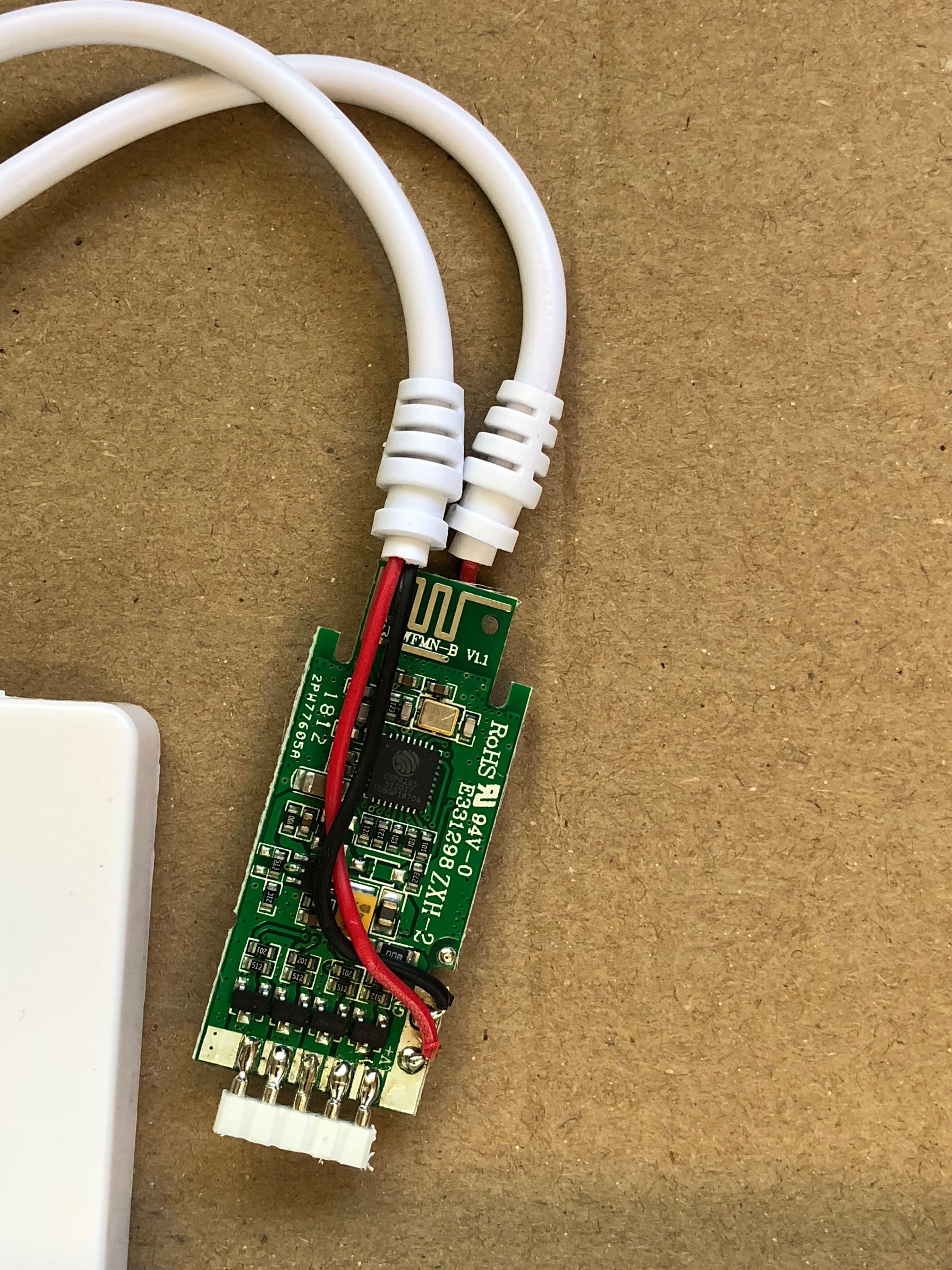
You can then access the TYWE3S (ESP) board. See here for the pinout, note that the image is the back of the board, but you need to connect to the front, so everything is swapped.
Connect to the highlighted pins as shown below. I soldered wires - but if you have pogo pins or similar, that would be a lot better.

The chip with connected wires:

Once you're connected, flash it in the usual way (remember to tie GPIO0 to ground). I used esptool.
Once it's flashed, refer to the Tasmota template repository for the current template.
Some notes for the unsupported LED string lights.
I pulled this apart, and found it had a chip labeled WB3L.
If you decide to pull one apart, don't be an idiot like me and use a knife to cut the glue, use a soldering iron or similar to melt the glue.
To pull the controller apart, I did the following:
Pop off the smaller cover over the wires. There are 2 square holes that I used a flat head screwdriver in to push it open. It was pretty tight as it was also breaking some glue holding it together, giving me this:

Next I broke the glue connecting the plastic and protecting the wires using a knife - don't do this (I cut the tracks and had to solder them again). Rather use a hot knife (or old soldering iron) to melt the glue away.
With that done, again using a screw driver I levered open the rest of the container. A couple of random points had glue, but slowly working my way around I was able to open it up.

Giving the inside of the device:

Getting the PCB out required some more fiddling to release any glue that was still holding it in place.
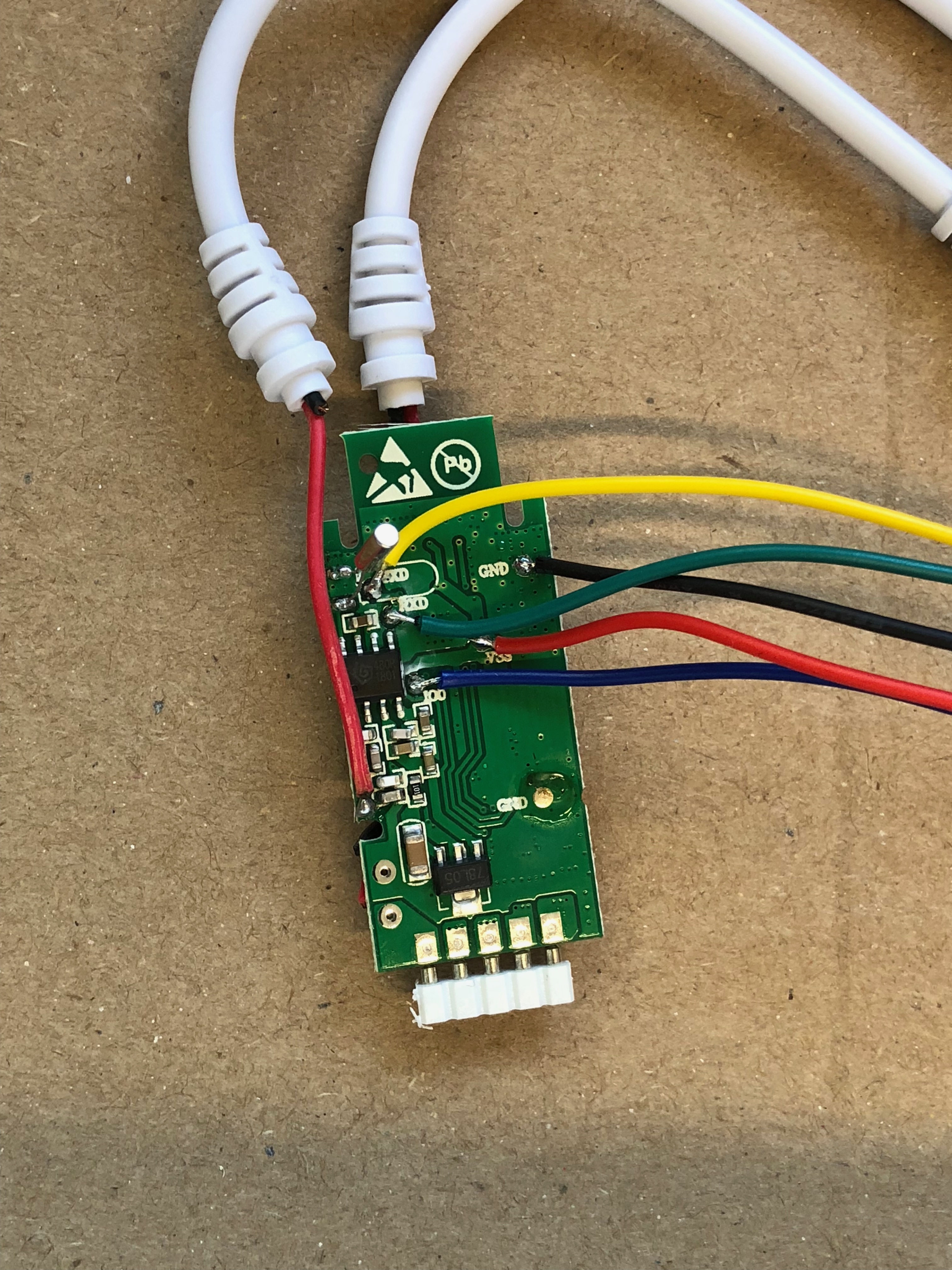
Once the main PCB is free, you can see the main controller chip and the rest of the board (this is after I repaired my cut tracks):

Notes about flashing the MakeGood 4 gang switch with Tasmota:
Use the following template:
{"NAME":"MakeGood 4 Gang","GPIO":[0,0,0,0,0,0,0,0,0,0,54,0,0],"FLAG":0,"BASE":54}
And once on the network and the template applied, run the following command:
Backlog TuyaMCU 11,1; TuyaMCU 12,2; TuyaMCU 13,3; TuyaMCU 14,4; TuyaMCU 33,104; TuyaMCU 31,103; TuyaMCU 32,102;
(From an email chain)
Trying to get my head around the planning of the LED lighting.
I’ve got the plan for the rooms:

I want to use something like these LED strips: https://www.aliexpress.com/item/DC24V-LED-Strip-5050-60LED-m-5M-IP20-IP65-LED-Flexible-strip-Light-5050-SMD-RGB/32852537610.html The question I can’t quite answer on these ones is I want the warm white, but can I get the RGB option and then be able to produce warm white from it?
And use this wif-fi controller: https://www.aliexpress.com/store/product/DC12-24V-RGB-WW-CW-LED-WIFI-Controller-4A-5Chanel-IOS-Android-Smart-Link-Timer-Music/1245436_32675853079.html
If I understand the specs of the wireless controller it should be able to run 3 strips of 40W (120W total) without too much hassle. I’m guessing that I will need to use the splitter cables on the output of the controllers to go to each of the LED strips. I’m also assuming that I can run the wiring from the power point/24V adapter for about 4m or so without too great a voltage drop that wouldn’t cause the lights to dim at the end. Thinking about the LED strips in blue in the diagram I’m expecting to run the adaptors and run all the wiring in the wall where the red x is marked’ I’ll have the gyprock off the wall in the small room so it’s nice and easy to put the wiring in there while it is off. That would make some long runs of wiring before getting to the LED strips themselves.
What do you think, am I heading down the right path or am I barking up the wrong tree?
This is working firmware we found after much messing around and completing the steps on the wiki at: https://openwrt.org/inbox/toh/netgear/netgear_stora
Not an issue, just somewhere to record some information.
A bunch of photos of the internals of the 3A smart home switch. (Purchased from ebay at https://www.ebay.com.au/itm/Smart-WiFi-Desk-Lamp-Light-Switch-Dimmer-GPO-4-Google-Home-Alexa-Voice-Control/183336271514 ). Used to help get a template for Tasmota
This is a 3A Smart Home Wi-Fi Three Gang Smart Switch, model HGZB-043.
The logic board behind the face plate includes the numbers:
120K3S_WIFI_SV5
FR4 94V0
T=1.0MM
20181011


A place for me to upload images and link them elsewhere on GitHub.


A declarative, efficient, and flexible JavaScript library for building user interfaces.
🖖 Vue.js is a progressive, incrementally-adoptable JavaScript framework for building UI on the web.
TypeScript is a superset of JavaScript that compiles to clean JavaScript output.
An Open Source Machine Learning Framework for Everyone
The Web framework for perfectionists with deadlines.
A PHP framework for web artisans
Bring data to life with SVG, Canvas and HTML. 📊📈🎉
JavaScript (JS) is a lightweight interpreted programming language with first-class functions.
Some thing interesting about web. New door for the world.
A server is a program made to process requests and deliver data to clients.
Machine learning is a way of modeling and interpreting data that allows a piece of software to respond intelligently.
Some thing interesting about visualization, use data art
Some thing interesting about game, make everyone happy.
We are working to build community through open source technology. NB: members must have two-factor auth.
Open source projects and samples from Microsoft.
Google ❤️ Open Source for everyone.
Alibaba Open Source for everyone
Data-Driven Documents codes.
China tencent open source team.