- Winget:
winget install -e --id PTRTECH.UVtools - Chocolatey:
choco install -y uvtools
Note: Winget is included on Windows 10 with recent updates and Windows 11 by default.
[ "$(command -v apt)" -a -z "$(command -v curl)" ] && sudo apt-get install -y curl
[ "$(command -v dnf)" -a -z "$(command -v curl)" ] && sudo dnf install -y curl
[ "$(command -v pacman)" -a -z "$(command -v curl)" ] && sudo pacman -S curl
[ "$(command -v zypper)" -a -z "$(command -v curl)" ] && sudo zypper install -y curl
bash -c "$(curl -fsSL https://raw.githubusercontent.com/sn4k3/UVtools/master/Scripts/install-uvtools.sh)"bash -c "$(curl -fsSL https://raw.githubusercontent.com/sn4k3/UVtools/master/Scripts/install-uvtools.sh)"# Replace x.x.x by the version you want to install
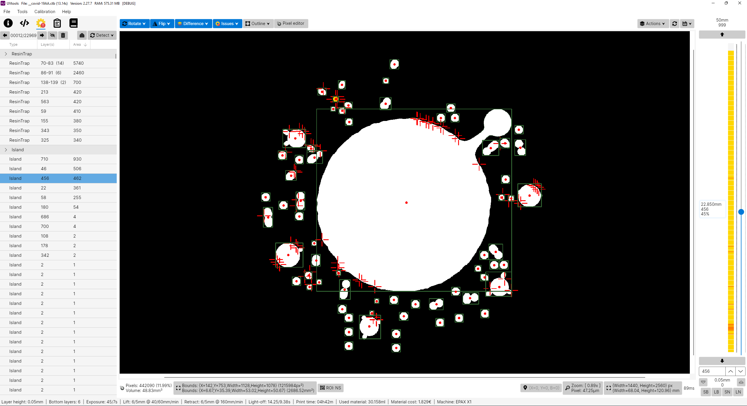
bash -c "$(curl -fsSL https://raw.githubusercontent.com/sn4k3/UVtools/master/Scripts/install-uvtools.sh)" -- x.x.xThis simple tool can give you insight of supports and find key failures.
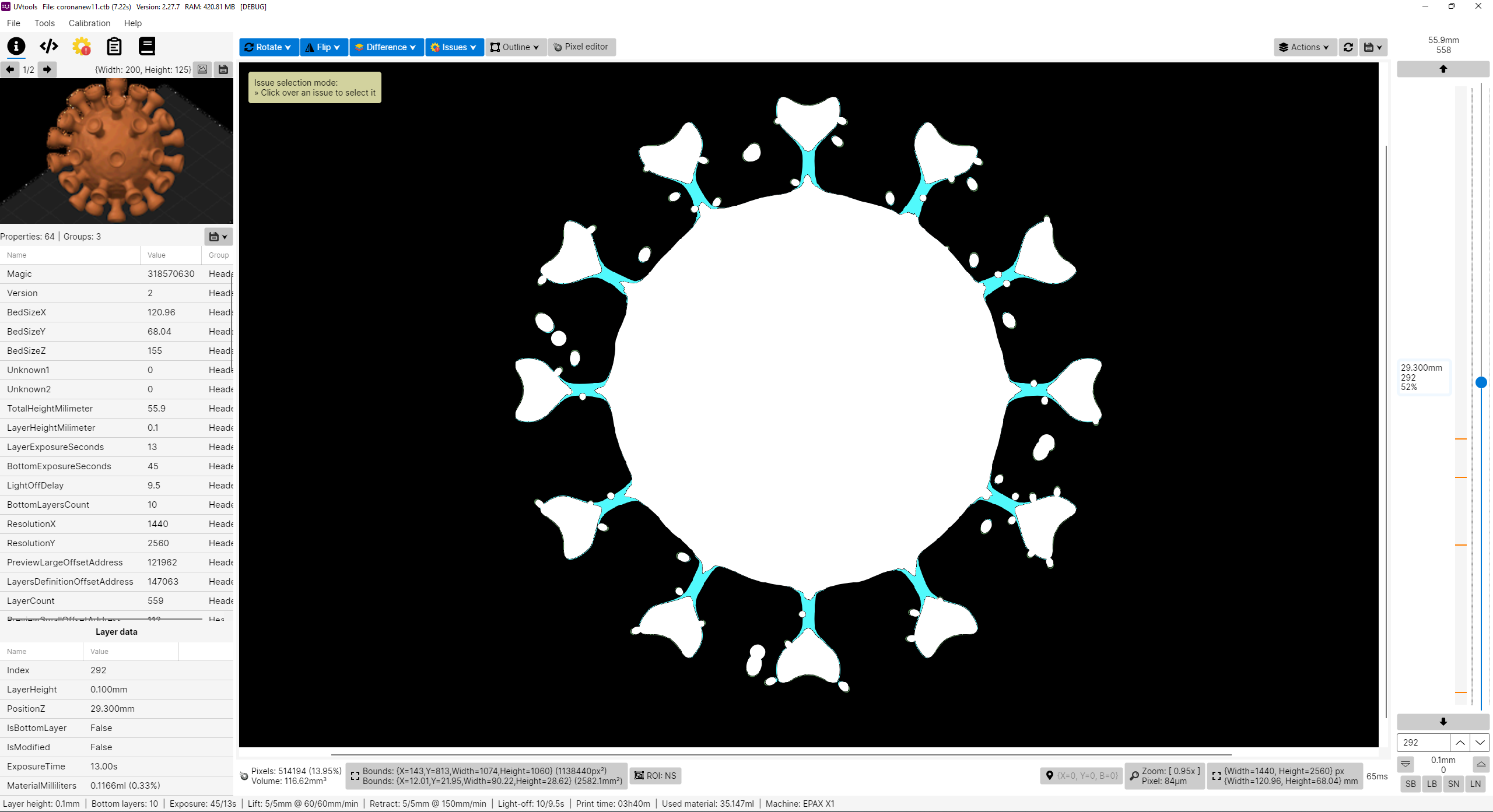
Did you forget what resin or other settings you used on a project?
This can also save you, check every setting that were used with or simply change them!
- Facebook group: https://www.facebook.com/groups/uvtools
- Discussions: https://github.com/sn4k3/UVtools/discussions
I don't own a Prusa SL1 or any other resin printer, for now I’m only a FDM user with Prusa MK3 and a Ender3. PrusaSlicer is my only choose, why? Because I think it's the best and feature more, at least for me, simple but powerful.
So why this project? Well in fact I’m looking for a resin printer and i like to study and learn first before buy, get good and don't regret, and while inspecting i found that resin printers firmwares are not as universal as FDM, too many file formats and there before each printer can use their own property file, this of course limit the software selection, for example, only PrusaSlicer can slice SL1 files. So with that in mind I'm preparing when I get a resin printer in future I can use PrusaSlicer instead of others. I've explored the other slicers and again, no one give me joy, and i feel them unstable, many users slice model on PrusaSlicer just to get those supports and export STL to load in another, that means again PrusaSlicer is on the win side, the problem is they can't slice directly on PrusaSlicer, so, in the end, my project aims to do almost that, configure a printer on PrusaSlicer, eg: EPAX X1, slice, export file, convert SL1 to native printer file and print.
Please note I don't own any resin printer! All my work is virtual and calculated, so, use experimental functions with care! Once things got confirmed a list will show. But also, I need victims for test subject. Proceed at your own risk!
- View, modify and extract layer by layer
- View, modify and extract thumbnails
- Export file to a folder
- View and edit all used properties/settings
- Many tools to mutate and filter layers
- Check for issues and repair/remove them as possible:
- Islands
- Overhangs
- Resin traps
- Suction cups
- Touching bounds
- Print height
- Empty layers
- Suggestions and auto corrections:
- Layer height
- Bottom layer count
- Wait time before cure
- Wait time after cure
- Transition layer count
- Model position
- Convert format to another format
- Calibration tests
- Portable (No installation needed)
- SL1, SL1S (PrusaSlicer)
- Photon, Photons, CBDDLP, CTB, PHZ, FDG, ZIP (Chitubox)
- PWS, PW0, PWX, DLP, DL2P, PWMO, PWMA, PWMS, PWMX, PMX2, PWMB, PWSQ, PX6S, PM3, PM3N, PM3M, PM3R, PM5, PM5S, PWC (Photon Workshop)
- JXS (GKone Slicer)
- ZCode (UnizMaker)
- ZCodex (Z-Suite)
- CWS (NovaMaker), RGB.CWS (Nova Bene4 Mono / Elfin2 Mono SE)
- XML.CWS (Wanhao Workshop)
- MDLP (Makerbase MKS-DLP v1)
- GR1 (GR1 Workshop)
- CXDLP, CXDLPV4 (Creality Box)
- GOO (Elegoo)
- LGS (Longer Orange 10), LGS30 (Longer Orange 30), LGS120 (Longer Orange 120), LGS4K (Longer Orange 4K & mono)
- Flashforge SVGX
- Anet N4, Anet N7
- QDT (Emake3D Galaxy 1)
- OSLA (Open SLA universal binary file)
- OSF (Vlare Open File Format)
- NanoDLP (Zip)
- UVJ (Vendor-neutral format for manual manipulation)
- VDT (Voxeldance Tango), VDA.ZIP (Voxeldance Additive)
- ZIP (Generic / Phrozen Zip)
- Image files (png, jpg, jpeg, jp2, tif, bmp, pbm, pgm, ras, sr)
- Installation: https://github.com/sn4k3/UVtools/wiki/Setup-PrusaSlicer
- Available printers: https://github.com/sn4k3/UVtools/tree/master/PrusaSlicer/printer
- Available profiles:
- From 0.01mm to 0.20mm
- Light, Medium and Heavy Supports
- Custom "Material Notes" and "Printer Notes" keywords:
- TransitionLayerCount_xxx: Sets the number of transition layers
- BottomLightOffDelay_xxx: Sets the bottom light off delay time in seconds
- LightOffDelay_xxx: Sets the light off delay time in seconds
- BottomWaitTimeBeforeCure_xxx: Sets the bottom wait time before cure in seconds
- WaitTimeBeforeCure_xxx: Sets the wait time before cure in seconds
- BottomWaitTimeAfterCure_xxx: Sets the bottom wait time after cure in seconds
- WaitTimeAfterCure_xxx: Sets the wait time after cure in seconds
- BottomLiftHeight_xxx: Sets the bottom lift height in millimeters
- BottomLiftSpeed_xxx: Sets the bottom lift speed in millimeters/minute
- BottomLiftHeight2_xxx: Sets the second bottom lift height in millimeters
- BottomLiftSpeed2_xxx: Sets the second bottom lift speed in millimeters/minute
- LiftHeight_xxx: Sets the lift height in millimeters
- LiftSpeed_xxx: Sets the lift speed in millimeters/minute
- LiftHeight2_xxx: Sets the second lift height in millimeters
- LiftSpeed2_xxx: Sets the second lift speed in millimeters/minute
- BottomWaitTimeAfterLift_xxx: Sets the bottom wait time after lift in seconds
- WaitTimeAfterLift_xxx: Sets the wait time after lift in seconds
- BottomRetractSpeed_xxx: Sets the bottom retract speed in millimeters/minute
- BottomRetractHeight2_xxx: Sets the second bottom retract height in millimeters
- BottomRetractSpeed2_xxx: Sets the second bottom retract speed in millimeters/minute
- RetractSpeed_xxx: Sets the retract speed in millimeters/minute
- RetractHeight2_xxx: Sets the second retract height in millimeters
- RetractSpeed2_xxx: Sets the second retract speed in millimeters/minute
- BottomLightPWM_xxx: Sets the bottom LED light power (0-255)
- LightPWM_xxx: Sets the LED light power (0-255)
- FILEVERSION_n: Sets the output file format version/revision
- FILEFORMAT_xxx: Sets the output file format extension to be auto converted once open on UVtools
- LAYERIMAGEFORMAT_xxx: Sets the layer image format required for the converted file if the format have multiple options (For Archives with PNG's)
Note that some variables will only work if the target format supports them, otherwise they will be ignored.
Replace the "xxx" by your desired value in the correct units
Usage:
  UVtoolsCmd [command] [options]

Options:
  -q, --quiet     Make output silent but exceptions error will still show
  --no-progress   Show no progress
  --dummy         Do not save alterations to file
  --core-version  Show core version information
  --version       Show version information
  -?, -h, --help  Show help and usage information

Commands:
  set-properties <input-file> <property=value>                                            Set properties in a file or to it layers with new values
  run <input-file> <classes/files>                                                        Run operations, suggestions and/or scripts
  convert <input-file> <target-type/ext> <output-file>                                    Convert input file into a output file format by a known type or extension []
  extract <input-file> <output-folder>                                                    Extract file contents to a folder []
  copy-parameters <input-file> <target-files>                                             Copy print parameters from one file to another
  set-preview, set-thumbnail <input-file> <file path|layer index|:random-layer|:heatmap>  Sets and replace thumbnail(s) in the file [default: :heatmap]
  compare <input-file-a> <input-file-b>                                                   Compare two files and output the differences
  print-issues <input-file>                                                               Detect and print issues
  print-properties <input-file>                                                           Prints available properties
  print-gcode <input-file>                                                                Prints the gcode of the file if available
  print-machines                                                                          Prints machine settings
  print-formats                                                                           Prints the available formats
Note: On each command you can use -? to see specific command help and extra options
- Open file(s):
- Syntax: UVtools <file1> [file2] [file3] ...
- Example 1: UVtools C:\model.osla
- Example 2: UVtools C:\model.zip D:\other_model.osla
- Note: When a invalid file is pass, the program will open as default.
- Redirect a command to UVtoolsCmd:
- Syntax: UVtools --cmd <commands ...>
- Example 1: UVtools --cmd convert C:\model.osla zip
- Note: This can be used when UVtoolsCmd is not directly exposed, for example if you are running via a .AppImage.
All commands will be redirected toUVtoolsCmdand the UI will not run. It still shows the terminal window.
The following commands are the old way and commands under the UI executable, they will be removed in near future, try to not use them, please prefer UVtoolsCmd.
- Convert a file into another type(s)
- Syntax: UVtools -c/--convert <input_file> <output_file1_or_ext> [output_file2_or_ext] ...
- Example 1: UVtools -c model.zip osla
- Example 2: UVtools -c model.zip model_converted.osla
- Example 3: UVtools --convert model.zip model_converted.osla model_converted.zcode
- Note: Nothing happen when providing wrong files, will quit.
- Extract a file to a folder
- Syntax: UVtools -e/--extract <input_file> [output_folder]
- Example 1: UVtools -e model.zip
- Example 2: UVtools -e model.zip mymodel
- Example 3: UVtools --extract model.zip .
- Note: Nothing happen when providing wrong files/folder, will quit.
- Export a file to a 3D mesh
- Syntax: UVtools --export-mesh <input_file> [output_mesh_file]
- Example 1: UVtools --export-mesh model.zip
- Example 2: UVtools --export-mesh model.zip model_exported.stl
- Note: Nothing happen when providing wrong files, will quit.
- Run a operation and save the file
- Syntax: UVtools --run-operation <input_file> <operation_file.uvtop>
- Example 1: UVtools --run-operation model.zip MyMorph.uvtop
- Note: Nothing happen when providing wrong files, will quit.
- Run a script and save the file
- Syntax: UVtools --run-script <input_file> <script_file.cs>
- Example 1: UVtools --run-script model.zip myScript.cs
- Note: Nothing happen when providing wrong files, will quit.
- Copy print parameters from one file to another
- Syntax: UVtools --copy-parameters <from_file> <to_file>
- Example 1: UVtools --copy-parameters model.zip otherfile.zip
- Note: Nothing happen when providing wrong files, will quit.
- Windows 7 SP1 or greater
- If on Windows 10/11 N or NK:
- Media Feature Pack must be installed
- Press Windows + R
- Type: appwiz.cpl (and press Enter key)
- Click on: Turn Windows features on or off
- Check the "Media Extensions" and click Ok
- If on Windows 10/11 N or NK:
- 8GB RAM or higher + 512MB per CPU core
- 64 bit System
- 1920 x 1080 @ 100% scale as minimum resolution
- 8GB RAM or higher + 512MB per CPU core
- 64 bit System
- 1920 x 1080 @ 100% scale as minimum resolution
Copy the following script, paste and run on a terminal:
(Required if you didn't use the auto installer or if it failed to detect and install dependencies)
[ "$(command -v apt-get)" -a -z "$(command -v curl)" ] && sudo apt-get install -y curl
[ "$(command -v pacman)" -a -z "$(command -v curl)" ] && sudo pacman -S curl
[ "$(command -v dnf)" -a -z "$(command -v curl)" ] && sudo dnf install -y curl
[ "$(command -v zypper)" -a -z "$(command -v curl)" ] && sudo zypper install -y curl
sudo bash -c "$(curl -fsSL https://raw.githubusercontent.com/sn4k3/UVtools/master/Scripts/install-dependencies.sh)"
To run UVtools open it folder on a terminal and call one of:
- Double-click
UVtoolsfile ./UVtoolsbash UVtools.shdotnet UVtools.dll[For universal package only, requires dotnet-runtime]- As a practical alternative you can create a shortcut on Desktop
If you downloaded the .AppImage package variant you must set run permissions to it before attempt to run it:

- macOS 10.15 Catalina or higher
- 8GB RAM or higher + 512MB per CPU core
- For Mac M1/M2 (ARM):
- Install via the auto installer
To run UVtools open it folder on a terminal and call one of:
- Double-click
UVtoolsfile ./UVtools.app/Contents/MacOS/UVtoolsbash UVtools.app/Contents/MacOS/UVtools.sh- As a practical alternative you can create a shortcut on Desktop
There are multiple ways to open your file in UVtools:
- Open UVtools and load your file (CTRL + O) (File -> Open)
- Open UVtools and drag and drop your file inside window
- Drag and drop file into UVtools.exe
- Set UVtools the default program to open your files
Are you a developer? This project include a .NET 6.0 library (UVtools.Core) that can be referenced in your application to make use of my work. Easy to use calls that allow you work with the formats. For more information navigate main code to see some calls.
Nuget package: https://www.nuget.org/packages/UVtools.Core
dotnet add package UVtools.CoreBuild directions
The fastest way to compile the project is by run the build/compile.bat, however if you wish to develop with visual studio follow the following steps:
- Install Visual Studio and include .NET development support
- Install the .NET 6.0 SDK if not included on previous installation
- Install the Avalonia for Visual Studio:
- Install the Wix Toolset: (Required only for MSI build, optional)
dotnet tool install --global wix- Visual Studio HeatWave extension
- Open UVtools.sln
- Build
- More file formats
- Clean up & performance (always)
- See features request under GitHub
All my work here is given for free (OpenSource), it took some hours to build, test and polish the program.
If you're happy to contribute for a better program and for my work i will appreciate the tip.
Use one of the following methods:


