This isn't an issue, but more of a call for help.
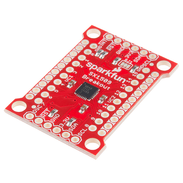
I'd like to use the Sparkfun SX1509 to control my SSD1306 DC, CS and reset lines.
Is there an easily enough way to do this? I tried my own implementation by editing ''https://github.com/adafruit/Adafruit_SSD1306" .cpp and .h, but was only able to access the SX1509 once.
/*!
 * @file Adafruit_SSD1306.h
 *
 * This is part of for Adafruit's SSD1306 library for monochrome
 * OLED displays: http://www.adafruit.com/category/63_98
 *
 * These displays use I2C or SPI to communicate. I2C requires 2 pins
 * (SCL+SDA) and optionally a RESET pin. SPI requires 4 pins (MOSI, SCK,
 * select, data/command) and optionally a reset pin. Hardware SPI or
 * 'bitbang' software SPI are both supported.
 *
 * Adafruit invests time and resources providing this open source code,
 * please support Adafruit and open-source hardware by purchasing
 * products from Adafruit!
 *
 * Written by Limor Fried/Ladyada for Adafruit Industries, with
 * contributions from the open source community.
 *
 * BSD license, all text above, and the splash screen header file,
 * must be included in any redistribution.
 *
 */
#include <SparkFunSX1509.h>  // Include SX1509 library

#ifndef _Adafruit_SSD1306_H_
#define _Adafruit_SSD1306_H_

// ONE of the following three lines must be #defined:
//#define SSD1306_128_64 ///< DEPRECTAED: old way to specify 128x64 screen
#define SSD1306_128_32 ///< DEPRECATED: old way to specify 128x32 screen
//#define SSD1306_96_16  ///< DEPRECATED: old way to specify 96x16 screen
// This establishes the screen dimensions in old Adafruit_SSD1306 sketches
// (NEW CODE SHOULD IGNORE THIS, USE THE CONSTRUCTORS THAT ACCEPT WIDTH
// AND HEIGHT ARGUMENTS).

// Uncomment to disable Adafruit splash logo
//#define SSD1306_NO_SPLASH

#if defined(ARDUINO_STM32_FEATHER)
typedef class HardwareSPI SPIClass;
#endif

#include <Adafruit_GFX.h>
#include <SPI.h>
#include <Wire.h>

#ifdef adaSX
#define adaSX
//#include <SparkFunSX1509.h>  // Include SX1509 library
#endif

#if defined(__AVR__)
typedef volatile uint8_t PortReg;
typedef uint8_t PortMask;
#define HAVE_PORTREG
#elif defined(__SAM3X8E__)
typedef volatile RwReg PortReg;
typedef uint32_t PortMask;
#define HAVE_PORTREG
#elif (defined(__arm__) || defined(ARDUINO_FEATHER52)) &&                      \
    !defined(ARDUINO_ARCH_MBED) && !defined(ARDUINO_ARCH_RP2040)
typedef volatile uint32_t PortReg;
typedef uint32_t PortMask;
#define HAVE_PORTREG
#endif

/// The following "raw" color names are kept for backwards client compatability
/// They can be disabled by predefining this macro before including the Adafruit
/// header client code will then need to be modified to use the scoped enum
/// values directly
#ifndef NO_ADAFRUIT_SSD1306_COLOR_COMPATIBILITY
#define BLACK SSD1306_BLACK     ///< Draw 'off' pixels
#define WHITE SSD1306_WHITE     ///< Draw 'on' pixels
#define INVERSE SSD1306_INVERSE ///< Invert pixels
#endif
/// fit into the SSD1306_ naming scheme
#define SSD1306_BLACK 0   ///< Draw 'off' pixels
#define SSD1306_WHITE 1   ///< Draw 'on' pixels
#define SSD1306_INVERSE 2 ///< Invert pixels

#define SSD1306_MEMORYMODE 0x20          ///< See datasheet
#define SSD1306_COLUMNADDR 0x21          ///< See datasheet
#define SSD1306_PAGEADDR 0x22            ///< See datasheet
#define SSD1306_SETCONTRAST 0x81         ///< See datasheet
#define SSD1306_CHARGEPUMP 0x8D          ///< See datasheet
#define SSD1306_SEGREMAP 0xA0            ///< See datasheet
#define SSD1306_DISPLAYALLON_RESUME 0xA4 ///< See datasheet
#define SSD1306_DISPLAYALLON 0xA5        ///< Not currently used
#define SSD1306_NORMALDISPLAY 0xA6       ///< See datasheet
#define SSD1306_INVERTDISPLAY 0xA7       ///< See datasheet
#define SSD1306_SETMULTIPLEX 0xA8        ///< See datasheet
#define SSD1306_DISPLAYOFF 0xAE          ///< See datasheet
#define SSD1306_DISPLAYON 0xAF           ///< See datasheet
#define SSD1306_COMSCANINC 0xC0          ///< Not currently used
#define SSD1306_COMSCANDEC 0xC8          ///< See datasheet
#define SSD1306_SETDISPLAYOFFSET 0xD3    ///< See datasheet
#define SSD1306_SETDISPLAYCLOCKDIV 0xD5  ///< See datasheet
#define SSD1306_SETPRECHARGE 0xD9        ///< See datasheet
#define SSD1306_SETCOMPINS 0xDA          ///< See datasheet
#define SSD1306_SETVCOMDETECT 0xDB       ///< See datasheet

#define SSD1306_SETLOWCOLUMN 0x00  ///< Not currently used
#define SSD1306_SETHIGHCOLUMN 0x10 ///< Not currently used
#define SSD1306_SETSTARTLINE 0x40  ///< See datasheet

#define SSD1306_EXTERNALVCC 0x01  ///< External display voltage source
#define SSD1306_SWITCHCAPVCC 0x02 ///< Gen. display voltage from 3.3V

#define SSD1306_RIGHT_HORIZONTAL_SCROLL 0x26              ///< Init rt scroll
#define SSD1306_LEFT_HORIZONTAL_SCROLL 0x27               ///< Init left scroll
#define SSD1306_VERTICAL_AND_RIGHT_HORIZONTAL_SCROLL 0x29 ///< Init diag scroll
#define SSD1306_VERTICAL_AND_LEFT_HORIZONTAL_SCROLL 0x2A  ///< Init diag scroll
#define SSD1306_DEACTIVATE_SCROLL 0x2E                    ///< Stop scroll
#define SSD1306_ACTIVATE_SCROLL 0x2F                      ///< Start scroll
#define SSD1306_SET_VERTICAL_SCROLL_AREA 0xA3             ///< Set scroll range

// Deprecated size stuff for backwards compatibility with old sketches
#if defined SSD1306_128_64
#define SSD1306_LCDWIDTH 128 ///< DEPRECATED: width w/SSD1306_128_64 defined
#define SSD1306_LCDHEIGHT 64 ///< DEPRECATED: height w/SSD1306_128_64 defined
#endif
#if defined SSD1306_128_32
#define SSD1306_LCDWIDTH 128 ///< DEPRECATED: width w/SSD1306_128_32 defined
#define SSD1306_LCDHEIGHT 32 ///< DEPRECATED: height w/SSD1306_128_32 defined
#endif
#if defined SSD1306_96_16
#define SSD1306_LCDWIDTH 96  ///< DEPRECATED: width w/SSD1306_96_16 defined
#define SSD1306_LCDHEIGHT 16 ///< DEPRECATED: height w/SSD1306_96_16 defined
#endif

/*!
    @brief  Class that stores state and functions for interacting with
            SSD1306 OLED displays.
*/


class Adafruit_SSD1306 : public Adafruit_GFX {
public:
  // NEW CONSTRUCTORS -- recommended for new projects
  Adafruit_SSD1306(uint8_t w, uint8_t h, TwoWire *twi = &Wire,
                   int8_t rst_pin = -1, uint32_t clkDuring = 400000UL,
                   uint32_t clkAfter = 100000UL);
  Adafruit_SSD1306(uint8_t w, uint8_t h, int8_t mosi_pin, int8_t sclk_pin,
                   int8_t dc_pin, int8_t rst_pin, int8_t cs_pin);
  Adafruit_SSD1306(uint8_t w, uint8_t h, SPIClass *spi, int8_t dc_pin,
                   int8_t rst_pin, int8_t cs_pin, uint32_t bitrate = 8000000UL);

	//EB
	void whichOne(SX1509 inQuestion);

	void Adafruit_SSD1306SX(int interface, boolean mUsing);
	SX1509 sxLive;
  	SX1509 sxL;
  	SX1509 sxR;
  	boolean startLRSX(boolean xc, byte address);
  	boolean getLRSX(boolean xc);
	boolean usingSX;
  	boolean leftOrRight;


  // DEPRECATED CONSTRUCTORS - for back compatibility, avoid in new projects
  Adafruit_SSD1306(int8_t mosi_pin, int8_t sclk_pin, int8_t dc_pin,
                   int8_t rst_pin, int8_t cs_pin);
  Adafruit_SSD1306(int8_t dc_pin, int8_t rst_pin, int8_t cs_pin);
  Adafruit_SSD1306(int8_t rst_pin = -1);

  ~Adafruit_SSD1306(void);

  bool begin(uint8_t switchvcc = SSD1306_SWITCHCAPVCC, uint8_t i2caddr = 0,
             bool reset = true, bool periphBegin = true);
  void display(void);
  void clearDisplay(void);
  void invertDisplay(bool i);
  void dim(bool dim);
  void drawPixel(int16_t x, int16_t y, uint16_t color);
  virtual void drawFastHLine(int16_t x, int16_t y, int16_t w, uint16_t color);
  virtual void drawFastVLine(int16_t x, int16_t y, int16_t h, uint16_t color);
  void startscrollright(uint8_t start, uint8_t stop);
  void startscrollleft(uint8_t start, uint8_t stop);
  void startscrolldiagright(uint8_t start, uint8_t stop);
  void startscrolldiagleft(uint8_t start, uint8_t stop);
  void stopscroll(void);
  void ssd1306_command(uint8_t c);
  bool getPixel(int16_t x, int16_t y);
  uint8_t *getBuffer(void);

protected:
  inline void SPIwrite(uint8_t d) __attribute__((always_inline));
  void drawFastHLineInternal(int16_t x, int16_t y, int16_t w, uint16_t color);
  void drawFastVLineInternal(int16_t x, int16_t y, int16_t h, uint16_t color);
  void ssd1306_command1(uint8_t c);
  void ssd1306_commandList(const uint8_t *c, uint8_t n);

  SPIClass *spi;   ///< Initialized during construction when using SPI. See
                   ///< SPI.cpp, SPI.h
  TwoWire *wire;   ///< Initialized during construction when using I2C. See
                   ///< Wire.cpp, Wire.h
  uint8_t *buffer; ///< Buffer data used for display buffer. Allocated when
                   ///< begin method is called.
  int8_t i2caddr;  ///< I2C address initialized when begin method is called.
  int8_t vccstate; ///< VCC selection, set by begin method.
  int8_t page_end; ///< not used
  int8_t mosiPin;  ///< (Master Out Slave In) set when using SPI set during
                   ///< construction.
  int8_t clkPin;   ///< (Clock Pin) set when using SPI set during construction.
  int8_t dcPin;    ///< (Data Pin) set when using SPI set during construction.
  int8_t
      csPin; ///< (Chip Select Pin) set when using SPI set during construction.
  int8_t rstPin; ///< Display reset pin assignment. Set during construction.

#ifdef HAVE_PORTREG
  PortReg *mosiPort, *clkPort, *dcPort, *csPort;
  PortMask mosiPinMask, clkPinMask, dcPinMask, csPinMask;
#endif
#if ARDUINO >= 157
  uint32_t wireClk;    ///< Wire speed for SSD1306 transfers
  uint32_t restoreClk; ///< Wire speed following SSD1306 transfers
#endif
  uint8_t contrast; ///< normal contrast setting for this device
#if defined(SPI_HAS_TRANSACTION)
protected:
  // Allow sub-class to change
  SPISettings spiSettings;
#endif
};

#endif // _Adafruit_SSD1306_H_
/*!
* @file Adafruit_SSD1306.cpp
*
* @mainpage Arduino library for monochrome OLEDs based on SSD1306 drivers.
*
* @section intro_sec Introduction
*
* This is documentation for Adafruit's SSD1306 library for monochrome
* OLED displays: http://www.adafruit.com/category/63_98
*
* These displays use I2C or SPI to communicate. I2C requires 2 pins
* (SCL+SDA) and optionally a RESET pin. SPI requires 4 pins (MOSI, SCK,
* select, data/command) and optionally a reset pin. Hardware SPI or
* 'bitbang' software SPI are both supported.
*
* Adafruit invests time and resources providing this open source code,
* please support Adafruit and open-source hardware by purchasing
* products from Adafruit!
*
* @section dependencies Dependencies
*
* This library depends on <a
* href="https://github.com/adafruit/Adafruit-GFX-Library"> Adafruit_GFX</a>
* being present on your system. Please make sure you have installed the latest
* version before using this library.
*
* @section author Author
*
* Written by Limor Fried/Ladyada for Adafruit Industries, with
* contributions from the open source community.
*
* @section license License
*
* BSD license, all text above, and the splash screen included below,
* must be included in any redistribution.
*
*/
#ifdef __AVR__
#include <avr/pgmspace.h>
#elif defined(ESP8266) || defined(ESP32) || defined(ARDUINO_ARCH_RP2040)
#include <pgmspace.h>
#else
#define pgm_read_byte(addr) \
(*(const unsigned char *)(addr)) ///< PROGMEM workaround for non-AVR
#endif
#if !defined(__ARM_ARCH) && !defined(ENERGIA) && !defined(ESP8266) && \
!defined(ESP32) && !defined(__arc__)
#include <util/delay.h>
#endif
#include "Adafruit_SSD1306.h"
#include "splash.h"
#include <Adafruit_GFX.h>
//#include <SparkFunSX1509.h> // Include SX1509 library
#ifdef adaSX
#define adaSX
#include <SparkFunSX1509.h> // Include SX1509 library
#endif
// SOME DEFINES AND STATIC VARIABLES USED INTERNALLY -----------------------
#if defined(I2C_BUFFER_LENGTH)
#define WIRE_MAX min(256, I2C_BUFFER_LENGTH) ///< Particle or similar Wire lib
#elif defined(BUFFER_LENGTH)
#define WIRE_MAX min(256, BUFFER_LENGTH) ///< AVR or similar Wire lib
#elif defined(SERIAL_BUFFER_SIZE)
#define WIRE_MAX \
min(255, SERIAL_BUFFER_SIZE - 1) ///< Newer Wire uses RingBuffer
#else
#define WIRE_MAX 32 ///< Use common Arduino core default
#endif
#define ssd1306_swap(a, b) \
(((a) ^= (b)), ((b) ^= (a)), ((a) ^= (b))) ///< No-temp-var swap operation
#if ARDUINO >= 100
#define WIRE_WRITE wire->write ///< Wire write function in recent Arduino lib
#else
#define WIRE_WRITE wire->send ///< Wire write function in older Arduino lib
#endif
//#ifdef HAVE_PORTREG
//#define SSD1306_SELECT *csPort &= ~csPinMask; ///< Device select
//#define SSD1306_DESELECT *csPort |= csPinMask; ///< Device deselect
//#define SSD1306_MODE_COMMAND *dcPort &= ~dcPinMask; ///< Command mode
//#define SSD1306_MODE_DATA *dcPort |= dcPinMask; ///< Data mode
//#else
/*
#ifdef adaSX
#define SSD1306_SELECT digitalWrite(csPin, LOW); ///< Device select
#define SSD1306_DESELECT digitalWrite(csPin, HIGH); ///< Device deselect
#define SSD1306_MODE_COMMAND digitalWrite(dcPin, LOW); ///< Command mode
#define SSD1306_MODE_DATA digitalWrite(dcPin, HIGH); ///< Data mode
#else
*/
#define SSD1306_SELECT sxLive.digitalWrite(csPin, LOW); ///< Device select //TBC
#define SSD1306_DESELECT sxLive.digitalWrite(csPin, HIGH); ///< Device deselect // Half OK
#define SSD1306_MODE_COMMAND sxLive.digitalWrite(dcPin, LOW); ///< Command mode // OK
#define SSD1306_MODE_DATA sxLive.digitalWrite(dcPin, HIGH); ///< Data mode //OK
//#endif
//#endif
#if (ARDUINO >= 157) && !defined(ARDUINO_STM32_FEATHER)
#define SETWIRECLOCK wire->setClock(wireClk) ///< Set before I2C transfer
#define RESWIRECLOCK wire->setClock(restoreClk) ///< Restore after I2C xfer
#else // setClock() is not present in older Arduino Wire lib (or WICED)
#define SETWIRECLOCK ///< Dummy stand-in define
#define RESWIRECLOCK ///< keeps compiler happy
#endif
#if defined(SPI_HAS_TRANSACTION)
#define SPI_TRANSACTION_START spi->beginTransaction(spiSettings) ///< Pre-SPI
#define SPI_TRANSACTION_END spi->endTransaction() ///< Post-SPI
#else // SPI transactions likewise not present in older Arduino SPI lib
#define SPI_TRANSACTION_START ///< Dummy stand-in define
#define SPI_TRANSACTION_END ///< keeps compiler happy
#endif
// The definition of 'transaction' is broadened a bit in the context of
// this library -- referring not just to SPI transactions (if supported
// in the version of the SPI library being used), but also chip select
// (if SPI is being used, whether hardware or soft), and also to the
// beginning and end of I2C transfers (the Wire clock may be sped up before
// issuing data to the display, then restored to the default rate afterward
// so other I2C device types still work). All of these are encapsulated
// in the TRANSACTION_* macros.
// Check first if Wire, then hardware SPI, then soft SPI:
#define TRANSACTION_START \
if (wire) { \
SETWIRECLOCK; \
} else { \
if (spi) { \
SPI_TRANSACTION_START; \
} \
SSD1306_SELECT; \
} ///< Wire, SPI or bitbang transfer setup
#define TRANSACTION_END \
if (wire) { \
RESWIRECLOCK; \
} else { \
SSD1306_DESELECT; \
if (spi) { \
SPI_TRANSACTION_END; \
} \
} ///< Wire, SPI or bitbang transfer end
// CONSTRUCTORS, DESTRUCTOR ------------------------------------------------
/*!
@brief Constructor for I2C-interfaced SSD1306 displays.
@param w
Display width in pixels
@param h
Display height in pixels
@param twi
Pointer to an existing TwoWire instance (e.g. &Wire, the
microcontroller's primary I2C bus).
@param rst_pin
Reset pin (using Arduino pin numbering), or -1 if not used
(some displays might be wired to share the microcontroller's
reset pin).
@param clkDuring
Speed (in Hz) for Wire transmissions in SSD1306 library calls.
Defaults to 400000 (400 KHz), a known 'safe' value for most
microcontrollers, and meets the SSD1306 datasheet spec.
Some systems can operate I2C faster (800 KHz for ESP32, 1 MHz
for many other 32-bit MCUs), and some (perhaps not all)
SSD1306's can work with this -- so it's optionally be specified
here and is not a default behavior. (Ignored if using pre-1.5.7
Arduino software, which operates I2C at a fixed 100 KHz.)
@param clkAfter
Speed (in Hz) for Wire transmissions following SSD1306 library
calls. Defaults to 100000 (100 KHz), the default Arduino Wire
speed. This is done rather than leaving it at the 'during' speed
because other devices on the I2C bus might not be compatible
with the faster rate. (Ignored if using pre-1.5.7 Arduino
software, which operates I2C at a fixed 100 KHz.)
@return Adafruit_SSD1306 object.
@note Call the object's begin() function before use -- buffer
allocation is performed there!
*/
Adafruit_SSD1306::Adafruit_SSD1306(uint8_t w, uint8_t h, TwoWire* twi,
int8_t rst_pin, uint32_t clkDuring,
uint32_t clkAfter)
: Adafruit_GFX(w, h), spi(NULL), wire(twi ? twi : &Wire), buffer(NULL),
mosiPin(-1), clkPin(-1), dcPin(-1), csPin(-1), rstPin(rst_pin)
#if ARDUINO >= 157
,
wireClk(clkDuring), restoreClk(clkAfter)
#endif
{
}
/*!
@brief Constructor for SPI SSD1306 displays, using software (bitbang)
SPI.
@param w
Display width in pixels
@param h
Display height in pixels
@param mosi_pin
MOSI (master out, slave in) pin (using Arduino pin numbering).
This transfers serial data from microcontroller to display.
@param sclk_pin
SCLK (serial clock) pin (using Arduino pin numbering).
This clocks each bit from MOSI.
@param dc_pin
Data/command pin (using Arduino pin numbering), selects whether
display is receiving commands (low) or data (high).
@param rst_pin
Reset pin (using Arduino pin numbering), or -1 if not used
(some displays might be wired to share the microcontroller's
reset pin).
@param cs_pin
Chip-select pin (using Arduino pin numbering) for sharing the
bus with other devices. Active low.
@return Adafruit_SSD1306 object.
@note Call the object's begin() function before use -- buffer
allocation is performed there!
*/
Adafruit_SSD1306::Adafruit_SSD1306(uint8_t w, uint8_t h, int8_t mosi_pin,
int8_t sclk_pin, int8_t dc_pin,
int8_t rst_pin, int8_t cs_pin)
: Adafruit_GFX(w, h), spi(NULL), wire(NULL), buffer(NULL),
mosiPin(mosi_pin), clkPin(sclk_pin), dcPin(dc_pin), csPin(cs_pin),
rstPin(rst_pin) {}
/*!
@brief Constructor for SPI SSD1306 displays, using native hardware SPI.
@param w
Display width in pixels
@param h
Display height in pixels
@param spi_ptr
Pointer to an existing SPIClass instance (e.g. &SPI, the
microcontroller's primary SPI bus).
@param dc_pin
Data/command pin (using Arduino pin numbering), selects whether
display is receiving commands (low) or data (high).
@param rst_pin
Reset pin (using Arduino pin numbering), or -1 if not used
(some displays might be wired to share the microcontroller's
reset pin).
@param cs_pin
Chip-select pin (using Arduino pin numbering) for sharing the
bus with other devices. Active low.
@param bitrate
SPI clock rate for transfers to this display. Default if
unspecified is 8000000UL (8 MHz).
@return Adafruit_SSD1306 object.
@note Call the object's begin() function before use -- buffer
allocation is performed there!
*/
Adafruit_SSD1306::Adafruit_SSD1306(uint8_t w, uint8_t h, SPIClass* spi_ptr,
int8_t dc_pin, int8_t rst_pin, int8_t cs_pin,
uint32_t bitrate)
: Adafruit_GFX(w, h), spi(spi_ptr ? spi_ptr : &SPI), wire(NULL),
buffer(NULL), mosiPin(-1), clkPin(-1), dcPin(dc_pin), csPin(cs_pin),
rstPin(rst_pin) {
#ifdef SPI_HAS_TRANSACTION
spiSettings = SPISettings(bitrate, MSBFIRST, SPI_MODE0);
#endif
}
/*!
@brief DEPRECATED constructor for SPI SSD1306 displays, using software
(bitbang) SPI. Provided for older code to maintain compatibility
with the current library. Screen size is determined by enabling
one of the SSD1306_* size defines in Adafruit_SSD1306.h. New
code should NOT use this.
@param mosi_pin
MOSI (master out, slave in) pin (using Arduino pin numbering).
This transfers serial data from microcontroller to display.
@param sclk_pin
SCLK (serial clock) pin (using Arduino pin numbering).
This clocks each bit from MOSI.
@param dc_pin
Data/command pin (using Arduino pin numbering), selects whether
display is receiving commands (low) or data (high).
@param rst_pin
Reset pin (using Arduino pin numbering), or -1 if not used
(some displays might be wired to share the microcontroller's
reset pin).
@param cs_pin
Chip-select pin (using Arduino pin numbering) for sharing the
bus with other devices. Active low.
@return Adafruit_SSD1306 object.
@note Call the object's begin() function before use -- buffer
allocation is performed there!
*/
Adafruit_SSD1306::Adafruit_SSD1306(int8_t mosi_pin, int8_t sclk_pin,
int8_t dc_pin, int8_t rst_pin, int8_t cs_pin)
: Adafruit_GFX(SSD1306_LCDWIDTH, SSD1306_LCDHEIGHT), spi(NULL), wire(NULL),
buffer(NULL), mosiPin(mosi_pin), clkPin(sclk_pin), dcPin(dc_pin),
csPin(cs_pin), rstPin(rst_pin) {}
/*!
@brief DEPRECATED constructor for SPI SSD1306 displays, using native
hardware SPI. Provided for older code to maintain compatibility
with the current library. Screen size is determined by enabling
one of the SSD1306_* size defines in Adafruit_SSD1306.h. New
code should NOT use this. Only the primary SPI bus is supported,
and bitrate is fixed at 8 MHz.
@param dc_pin
Data/command pin (using Arduino pin numbering), selects whether
display is receiving commands (low) or data (high).
@param rst_pin
Reset pin (using Arduino pin numbering), or -1 if not used
(some displays might be wired to share the microcontroller's
reset pin).
@param cs_pin
Chip-select pin (using Arduino pin numbering) for sharing the
bus with other devices. Active low.
@return Adafruit_SSD1306 object.
@note Call the object's begin() function before use -- buffer
allocation is performed there!
*/
Adafruit_SSD1306::Adafruit_SSD1306(int8_t dc_pin, int8_t rst_pin, int8_t cs_pin)
: Adafruit_GFX(SSD1306_LCDWIDTH, SSD1306_LCDHEIGHT), spi(&SPI), wire(NULL),
buffer(NULL), mosiPin(-1), clkPin(-1), dcPin(dc_pin), csPin(cs_pin),
rstPin(rst_pin) {
#ifdef SPI_HAS_TRANSACTION
spiSettings = SPISettings(8000000, MSBFIRST, SPI_MODE0);
#endif
}
/*!
@brief DEPRECATED constructor for I2C SSD1306 displays. Provided for
older code to maintain compatibility with the current library.
Screen size is determined by enabling one of the SSD1306_* size
defines in Adafruit_SSD1306.h. New code should NOT use this.
Only the primary I2C bus is supported.
@param rst_pin
Reset pin (using Arduino pin numbering), or -1 if not used
(some displays might be wired to share the microcontroller's
reset pin).
@return Adafruit_SSD1306 object.
@note Call the object's begin() function before use -- buffer
allocation is performed there!
*/
Adafruit_SSD1306::Adafruit_SSD1306(int8_t rst_pin)
: Adafruit_GFX(SSD1306_LCDWIDTH, SSD1306_LCDHEIGHT), spi(NULL), wire(&Wire),
buffer(NULL), mosiPin(-1), clkPin(-1), dcPin(-1), csPin(-1),
rstPin(rst_pin) {}
/*!
@brief Destructor for Adafruit_SSD1306 object.
*/
Adafruit_SSD1306::~Adafruit_SSD1306(void) {
if (buffer) {
free(buffer);
buffer = NULL;
}
}
// LOW-LEVEL UTILS ---------------------------------------------------------
// Issue single byte out SPI, either soft or hardware as appropriate.
// SPI transaction/selection must be performed in calling function.
/*!
@brief Write a single byte to the SPI port.
@param d
Data byte to be written.
@return void
@note See HAVE_PORTREG which defines if the method uses a port or bit-bang
method
*/
inline void Adafruit_SSD1306::SPIwrite(uint8_t d) {
if (spi) {
(void)spi->transfer(d);
}
else {
for (uint8_t bit = 0x80; bit; bit >>= 1) {
#ifdef HAVE_PORTREG
if (d & bit)
*mosiPort |= mosiPinMask;
else
*mosiPort &= ~mosiPinMask;
*clkPort |= clkPinMask; // Clock high
*clkPort &= ~clkPinMask; // Clock low
#else
digitalWrite(mosiPin, d & bit);
digitalWrite(clkPin, HIGH);
digitalWrite(clkPin, LOW);
#endif
}
}
}
/*!
@brief Issue single command to SSD1306, using I2C or hard/soft SPI as
needed. Because command calls are often grouped, SPI transaction and
selection must be started/ended in calling function for efficiency. This is a
protected function, not exposed (see ssd1306_command() instead).
@param c
the command character to send to the display.
Refer to ssd1306 data sheet for commands
@return None (void).
@note
*/
void Adafruit_SSD1306::ssd1306_command1(uint8_t c) {
if (wire) { // I2C
wire->beginTransmission(i2caddr);
WIRE_WRITE((uint8_t)0x00); // Co = 0, D/C = 0
WIRE_WRITE(c);
wire->endTransmission();
}
else { // SPI (hw or soft) -- transaction started in calling function
sxLive.digitalWrite(dcPin, LOW);
//SSD1306_MODE_COMMAND
SPIwrite(c);
}
}
/*!
@brief Issue list of commands to SSD1306, same rules as above re:
transactions. This is a protected function, not exposed.
@param c
pointer to list of commands
@param n
number of commands in the list
@return None (void).
@note
*/
void Adafruit_SSD1306::ssd1306_commandList(const uint8_t* c, uint8_t n) {
if (wire) { // I2C
wire->beginTransmission(i2caddr);
WIRE_WRITE((uint8_t)0x00); // Co = 0, D/C = 0
uint16_t bytesOut = 1;
while (n--) {
if (bytesOut >= WIRE_MAX) {
wire->endTransmission();
wire->beginTransmission(i2caddr);
WIRE_WRITE((uint8_t)0x00); // Co = 0, D/C = 0
bytesOut = 1;
}
WIRE_WRITE(pgm_read_byte(c++));
bytesOut++;
}
wire->endTransmission();
}
else { // SPI -- transaction started in calling function
sxLive.digitalWrite(dcPin, LOW);
//SSD1306_MODE_COMMAND
while (n--)
SPIwrite(pgm_read_byte(c++));
}
}
// A public version of ssd1306_command1(), for existing user code that
// might rely on that function. This encapsulates the command transfer
// in a transaction start/end, similar to old library's handling of it.
/*!
@brief Issue a single low-level command directly to the SSD1306
display, bypassing the library.
@param c
Command to issue (0x00 to 0xFF, see datasheet).
@return None (void).
*/
void Adafruit_SSD1306::ssd1306_command(uint8_t c) {
TRANSACTION_START
ssd1306_command1(c);
TRANSACTION_END
}
// ALLOCATE & INIT DISPLAY -------------------------------------------------
/*!
@brief Allocate RAM for image buffer, initialize peripherals and pins.
@param vcs
VCC selection. Pass SSD1306_SWITCHCAPVCC to generate the display
voltage (step up) from the 3.3V source, or SSD1306_EXTERNALVCC
otherwise. Most situations with Adafruit SSD1306 breakouts will
want SSD1306_SWITCHCAPVCC.
@param addr
I2C address of corresponding SSD1306 display (or pass 0 to use
default of 0x3C for 128x32 display, 0x3D for all others).
SPI displays (hardware or software) do not use addresses, but
this argument is still required (pass 0 or any value really,
it will simply be ignored). Default if unspecified is 0.
@param reset
If true, and if the reset pin passed to the constructor is
valid, a hard reset will be performed before initializing the
display. If using multiple SSD1306 displays on the same bus, and
if they all share the same reset pin, you should only pass true
on the first display being initialized, false on all others,
else the already-initialized displays would be reset. Default if
unspecified is true.
@param periphBegin
If true, and if a hardware peripheral is being used (I2C or SPI,
but not software SPI), call that peripheral's begin() function,
else (false) it has already been done in one's sketch code.
Cases where false might be used include multiple displays or
other devices sharing a common bus, or situations on some
platforms where a nonstandard begin() function is available
(e.g. a TwoWire interface on non-default pins, as can be done
on the ESP8266 and perhaps others).
@return true on successful allocation/init, false otherwise.
Well-behaved code should check the return value before
proceeding.
@note MUST call this function before any drawing or updates!
*/
bool Adafruit_SSD1306::begin(uint8_t vcs, uint8_t addr, bool reset,
bool periphBegin) {
if ((!buffer) && !(buffer = (uint8_t*)malloc(WIDTH * ((HEIGHT + 7) / 8))))
return false;
clearDisplay();
#ifndef SSD1306_NO_SPLASH
if (HEIGHT > 32) {
drawBitmap((WIDTH - splash1_width) / 2, (HEIGHT - splash1_height) / 2,
splash1_data, splash1_width, splash1_height, 1);
}
else {
drawBitmap((WIDTH - splash2_width) / 2, (HEIGHT - splash2_height) / 2,
splash2_data, splash2_width, splash2_height, 1);
}
#endif
vccstate = vcs;
// Setup pin directions
if (wire) { // Using I2C
// If I2C address is unspecified, use default
// (0x3C for 32-pixel-tall displays, 0x3D for all others).
i2caddr = addr ? addr : ((HEIGHT == 32) ? 0x3C : 0x3D);
// TwoWire begin() function might be already performed by the calling
// function if it has unusual circumstances (e.g. TWI variants that
// can accept different SDA/SCL pins, or if two SSD1306 instances
// with different addresses -- only a single begin() is needed).
if (periphBegin)
wire->begin();
}
else { // Using one of the SPI modes, either soft or hardware
sxLive.pinMode(dcPin, OUTPUT); // Set data/command pin as output
sxLive.pinMode(csPin, OUTPUT); // Same for chip select
#ifdef HAVE_PORTREG
dcPort = (PortReg*)portOutputRegister(digitalPinToPort(dcPin));
dcPinMask = digitalPinToBitMask(dcPin);
csPort = (PortReg*)portOutputRegister(digitalPinToPort(csPin));
csPinMask = digitalPinToBitMask(csPin);
#endif
sxLive.digitalWrite(csPin, HIGH);
//SSD1306_DESELECT
if (spi) { // Hardware SPI
// SPI peripheral begin same as wire check above.
if (periphBegin)
spi->begin();
}
else { // Soft SPI
sxLive.pinMode(mosiPin, OUTPUT); // MOSI and SCLK outputs
sxLive.pinMode(clkPin, OUTPUT);
#ifdef HAVE_PORTREG
mosiPort = (PortReg*)portOutputRegister(digitalPinToPort(mosiPin));
mosiPinMask = digitalPinToBitMask(mosiPin);
clkPort = (PortReg*)portOutputRegister(digitalPinToPort(clkPin));
clkPinMask = digitalPinToBitMask(clkPin);
*clkPort &= ~clkPinMask; // Clock low
#else
digitalWrite(clkPin, LOW); // Clock low
#endif
}
}
// Reset SSD1306 if requested and reset pin specified in constructor
if (reset && (rstPin >= 0)) {
Serial.println("1 HERE Called: Pin: " + String(rstPin));
sxLive.pinMode(rstPin, OUTPUT);
sxLive.digitalWrite(rstPin, HIGH);
delay(2000); // VDD goes high at start, pause for 1 ms
Serial.println("2 HERE Called: Pin: " + String(rstPin));
sxLive.digitalWrite(rstPin, LOW); // Bring reset low
delay(2000); // Wait 10 ms
sxLive.digitalWrite(rstPin, HIGH); // Bring out of reset
Serial.println("3 HERE Called: Pin: " + String(rstPin));
}
TRANSACTION_START
// Init sequence
static const uint8_t PROGMEM init1[] = {SSD1306_DISPLAYOFF, // 0xAE
SSD1306_SETDISPLAYCLOCKDIV, // 0xD5
0x80, // the suggested ratio 0x80
SSD1306_SETMULTIPLEX
}; // 0xA8
ssd1306_commandList(init1, sizeof(init1));
ssd1306_command1(HEIGHT - 1);
static const uint8_t PROGMEM init2[] = {SSD1306_SETDISPLAYOFFSET, // 0xD3
0x0, // no offset
SSD1306_SETSTARTLINE | 0x0, // line #0
SSD1306_CHARGEPUMP
}; // 0x8D
ssd1306_commandList(init2, sizeof(init2));
ssd1306_command1((vccstate == SSD1306_EXTERNALVCC) ? 0x10 : 0x14);
static const uint8_t PROGMEM init3[] = {SSD1306_MEMORYMODE, // 0x20
0x00, // 0x0 act like ks0108
SSD1306_SEGREMAP | 0x1,
SSD1306_COMSCANDEC
};
ssd1306_commandList(init3, sizeof(init3));
uint8_t comPins = 0x02;
contrast = 0x8F;
if ((WIDTH == 128) && (HEIGHT == 32)) {
comPins = 0x02;
contrast = 0x8F;
}
else
if ((WIDTH == 128) && (HEIGHT == 64)) {
comPins = 0x12;
contrast = (vccstate == SSD1306_EXTERNALVCC) ? 0x9F : 0xCF;
}
else
if ((WIDTH == 96) && (HEIGHT == 16)) {
comPins = 0x2; // ada x12
contrast = (vccstate == SSD1306_EXTERNALVCC) ? 0x10 : 0xAF;
}
else {
// Other screen varieties -- TBD
}
ssd1306_command1(SSD1306_SETCOMPINS);
ssd1306_command1(comPins);
ssd1306_command1(SSD1306_SETCONTRAST);
ssd1306_command1(contrast);
ssd1306_command1(SSD1306_SETPRECHARGE); // 0xd9
ssd1306_command1((vccstate == SSD1306_EXTERNALVCC) ? 0x22 : 0xF1);
static const uint8_t PROGMEM init5[] = {
SSD1306_SETVCOMDETECT, // 0xDB
0x40,
SSD1306_DISPLAYALLON_RESUME, // 0xA4
SSD1306_NORMALDISPLAY, // 0xA6
SSD1306_DEACTIVATE_SCROLL,
SSD1306_DISPLAYON
}; // Main screen turn on
ssd1306_commandList(init5, sizeof(init5));
TRANSACTION_END
return true; // Success
}
// DRAWING FUNCTIONS -------------------------------------------------------
/*!
@brief Set/clear/invert a single pixel. This is also invoked by the
Adafruit_GFX library in generating many higher-level graphics
primitives.
@param x
Column of display -- 0 at left to (screen width - 1) at right.
@param y
Row of display -- 0 at top to (screen height -1) at bottom.
@param color
Pixel color, one of: SSD1306_BLACK, SSD1306_WHITE or
SSD1306_INVERSE.
@return None (void).
@note Changes buffer contents only, no immediate effect on display.
Follow up with a call to display(), or with other graphics
commands as needed by one's own application.
*/
void Adafruit_SSD1306::drawPixel(int16_t x, int16_t y, uint16_t color) {
if ((x >= 0) && (x < width()) && (y >= 0) && (y < height())) {
// Pixel is in-bounds. Rotate coordinates if needed.
switch (getRotation()) {
case 1:
ssd1306_swap(x, y);
x = WIDTH - x - 1;
break;
case 2:
x = WIDTH - x - 1;
y = HEIGHT - y - 1;
break;
case 3:
ssd1306_swap(x, y);
y = HEIGHT - y - 1;
break;
}
switch (color) {
case SSD1306_WHITE:
buffer[x + (y / 8) * WIDTH] |= (1 << (y & 7));
break;
case SSD1306_BLACK:
buffer[x + (y / 8) * WIDTH] &= ~(1 << (y & 7));
break;
case SSD1306_INVERSE:
buffer[x + (y / 8) * WIDTH] ^= (1 << (y & 7));
break;
}
}
}
/*!
@brief Clear contents of display buffer (set all pixels to off).
@return None (void).
@note Changes buffer contents only, no immediate effect on display.
Follow up with a call to display(), or with other graphics
commands as needed by one's own application.
*/
void Adafruit_SSD1306::clearDisplay(void) {
memset(buffer, 0, WIDTH * ((HEIGHT + 7) / 8));
}
/*!
@brief Draw a horizontal line. This is also invoked by the Adafruit_GFX
library in generating many higher-level graphics primitives.
@param x
Leftmost column -- 0 at left to (screen width - 1) at right.
@param y
Row of display -- 0 at top to (screen height -1) at bottom.
@param w
Width of line, in pixels.
@param color
Line color, one of: SSD1306_BLACK, SSD1306_WHITE or SSD1306_INVERSE.
@return None (void).
@note Changes buffer contents only, no immediate effect on display.
Follow up with a call to display(), or with other graphics
commands as needed by one's own application.
*/
void Adafruit_SSD1306::drawFastHLine(int16_t x, int16_t y, int16_t w,
uint16_t color) {
bool bSwap = false;
switch (rotation) {
case 1:
// 90 degree rotation, swap x & y for rotation, then invert x
bSwap = true;
ssd1306_swap(x, y);
x = WIDTH - x - 1;
break;
case 2:
// 180 degree rotation, invert x and y, then shift y around for height.
x = WIDTH - x - 1;
y = HEIGHT - y - 1;
x -= (w - 1);
break;
case 3:
// 270 degree rotation, swap x & y for rotation,
// then invert y and adjust y for w (not to become h)
bSwap = true;
ssd1306_swap(x, y);
y = HEIGHT - y - 1;
y -= (w - 1);
break;
}
if (bSwap)
drawFastVLineInternal(x, y, w, color);
else
drawFastHLineInternal(x, y, w, color);
}
/*!
@brief Draw a horizontal line with a width and color. Used by public
methods drawFastHLine,drawFastVLine
@param x
Leftmost column -- 0 at left to (screen width - 1) at right.
@param y
Row of display -- 0 at top to (screen height -1) at bottom.
@param w
Width of line, in pixels.
@param color
Line color, one of: SSD1306_BLACK, SSD1306_WHITE or
SSD1306_INVERSE.
@return None (void).
@note Changes buffer contents only, no immediate effect on display.
Follow up with a call to display(), or with other graphics
commands as needed by one's own application.
*/
void Adafruit_SSD1306::drawFastHLineInternal(int16_t x, int16_t y, int16_t w,
uint16_t color) {
if ((y >= 0) && (y < HEIGHT)) { // Y coord in bounds?
if (x < 0) { // Clip left
w += x;
x = 0;
}
if ((x + w) > WIDTH) { // Clip right
w = (WIDTH - x);
}
if (w > 0) { // Proceed only if width is positive
uint8_t* pBuf = &buffer[(y / 8) * WIDTH + x], mask = 1 << (y & 7);
switch (color) {
case SSD1306_WHITE:
while (w--) {
*pBuf++ |= mask;
};
break;
case SSD1306_BLACK:
mask = ~mask;
while (w--) {
*pBuf++ &= mask;
};
break;
case SSD1306_INVERSE:
while (w--) {
*pBuf++ ^= mask;
};
break;
}
}
}
}
/*!
@brief Draw a vertical line. This is also invoked by the Adafruit_GFX
library in generating many higher-level graphics primitives.
@param x
Column of display -- 0 at left to (screen width -1) at right.
@param y
Topmost row -- 0 at top to (screen height - 1) at bottom.
@param h
Height of line, in pixels.
@param color
Line color, one of: SSD1306_BLACK, SSD1306_WHITE or SSD1306_INVERSE.
@return None (void).
@note Changes buffer contents only, no immediate effect on display.
Follow up with a call to display(), or with other graphics
commands as needed by one's own application.
*/
void Adafruit_SSD1306::drawFastVLine(int16_t x, int16_t y, int16_t h,
uint16_t color) {
bool bSwap = false;
switch (rotation) {
case 1:
// 90 degree rotation, swap x & y for rotation,
// then invert x and adjust x for h (now to become w)
bSwap = true;
ssd1306_swap(x, y);
x = WIDTH - x - 1;
x -= (h - 1);
break;
case 2:
// 180 degree rotation, invert x and y, then shift y around for height.
x = WIDTH - x - 1;
y = HEIGHT - y - 1;
y -= (h - 1);
break;
case 3:
// 270 degree rotation, swap x & y for rotation, then invert y
bSwap = true;
ssd1306_swap(x, y);
y = HEIGHT - y - 1;
break;
}
if (bSwap)
drawFastHLineInternal(x, y, h, color);
else
drawFastVLineInternal(x, y, h, color);
}
/*!
@brief Draw a vertical line with a width and color. Used by public method
drawFastHLine,drawFastVLine
@param x
Leftmost column -- 0 at left to (screen width - 1) at right.
@param __y
Row of display -- 0 at top to (screen height -1) at bottom.
@param __h height of the line in pixels
@param color
Line color, one of: SSD1306_BLACK, SSD1306_WHITE or
SSD1306_INVERSE.
@return None (void).
@note Changes buffer contents only, no immediate effect on display.
Follow up with a call to display(), or with other graphics
commands as needed by one's own application.
*/
void Adafruit_SSD1306::drawFastVLineInternal(int16_t x, int16_t __y,
int16_t __h, uint16_t color) {
if ((x >= 0) && (x < WIDTH)) { // X coord in bounds?
if (__y < 0) { // Clip top
__h += __y;
__y = 0;
}
if ((__y + __h) > HEIGHT) { // Clip bottom
__h = (HEIGHT - __y);
}
if (__h > 0) { // Proceed only if height is now positive
// this display doesn't need ints for coordinates,
// use local byte registers for faster juggling
uint8_t y = __y, h = __h;
uint8_t* pBuf = &buffer[(y / 8) * WIDTH + x];
// do the first partial byte, if necessary - this requires some masking
uint8_t mod = (y & 7);
if (mod) {
// mask off the high n bits we want to set
mod = 8 - mod;
// note - lookup table results in a nearly 10% performance
// improvement in fill* functions
// uint8_t mask = ~(0xFF >> mod);
static const uint8_t PROGMEM premask[8] = {0x00, 0x80, 0xC0, 0xE0,
0xF0, 0xF8, 0xFC, 0xFE
};
uint8_t mask = pgm_read_byte(&premask[mod]);
// adjust the mask if we're not going to reach the end of this byte
if (h < mod)
mask &= (0XFF >> (mod - h));
switch (color) {
case SSD1306_WHITE:
*pBuf |= mask;
break;
case SSD1306_BLACK:
*pBuf &= ~mask;
break;
case SSD1306_INVERSE:
*pBuf ^= mask;
break;
}
pBuf += WIDTH;
}
if (h >= mod) { // More to go?
h -= mod;
// Write solid bytes while we can - effectively 8 rows at a time
if (h >= 8) {
if (color == SSD1306_INVERSE) {
// separate copy of the code so we don't impact performance of
// black/white write version with an extra comparison per loop
do {
*pBuf ^= 0xFF; // Invert byte
pBuf += WIDTH; // Advance pointer 8 rows
h -= 8; // Subtract 8 rows from height
} while (h >= 8);
}
else {
// store a local value to work with
uint8_t val = (color != SSD1306_BLACK) ? 255 : 0;
do {
*pBuf = val; // Set byte
pBuf += WIDTH; // Advance pointer 8 rows
h -= 8; // Subtract 8 rows from height
} while (h >= 8);
}
}
if (h) { // Do the final partial byte, if necessary
mod = h & 7;
// this time we want to mask the low bits of the byte,
// vs the high bits we did above
// uint8_t mask = (1 << mod) - 1;
// note - lookup table results in a nearly 10% performance
// improvement in fill* functions
static const uint8_t PROGMEM postmask[8] = {0x00, 0x01, 0x03, 0x07,
0x0F, 0x1F, 0x3F, 0x7F
};
uint8_t mask = pgm_read_byte(&postmask[mod]);
switch (color) {
case SSD1306_WHITE:
*pBuf |= mask;
break;
case SSD1306_BLACK:
*pBuf &= ~mask;
break;
case SSD1306_INVERSE:
*pBuf ^= mask;
break;
}
}
}
} // endif positive height
} // endif x in bounds
}
/*!
@brief Return color of a single pixel in display buffer.
@param x
Column of display -- 0 at left to (screen width - 1) at right.
@param y
Row of display -- 0 at top to (screen height -1) at bottom.
@return true if pixel is set (usually SSD1306_WHITE, unless display invert
mode is enabled), false if clear (SSD1306_BLACK).
@note Reads from buffer contents; may not reflect current contents of
screen if display() has not been called.
*/
bool Adafruit_SSD1306::getPixel(int16_t x, int16_t y) {
if ((x >= 0) && (x < width()) && (y >= 0) && (y < height())) {
// Pixel is in-bounds. Rotate coordinates if needed.
switch (getRotation()) {
case 1:
ssd1306_swap(x, y);
x = WIDTH - x - 1;
break;
case 2:
x = WIDTH - x - 1;
y = HEIGHT - y - 1;
break;
case 3:
ssd1306_swap(x, y);
y = HEIGHT - y - 1;
break;
}
return (buffer[x + (y / 8) * WIDTH] & (1 << (y & 7)));
}
return false; // Pixel out of bounds
}
/*!
@brief Get base address of display buffer for direct reading or writing.
@return Pointer to an unsigned 8-bit array, column-major, columns padded
to full byte boundary if needed.
*/
uint8_t* Adafruit_SSD1306::getBuffer(void) {
return buffer;
}
// REFRESH DISPLAY ---------------------------------------------------------
/*!
@brief Push data currently in RAM to SSD1306 display.
@return None (void).
@note Drawing operations are not visible until this function is
called. Call after each graphics command, or after a whole set
of graphics commands, as best needed by one's own application.
*/
void Adafruit_SSD1306::display(void) {
TRANSACTION_START
static const uint8_t PROGMEM dlist1[] = {
SSD1306_PAGEADDR,
0, // Page start address
0xFF, // Page end (not really, but works here)
SSD1306_COLUMNADDR, 0
}; // Column start address
ssd1306_commandList(dlist1, sizeof(dlist1));
ssd1306_command1(WIDTH - 1); // Column end address
#if defined(ESP8266)
// ESP8266 needs a periodic yield() call to avoid watchdog reset.
// With the limited size of SSD1306 displays, and the fast bitrate
// being used (1 MHz or more), I think one yield() immediately before
// a screen write and one immediately after should cover it. But if
// not, if this becomes a problem, yields() might be added in the
// 32-byte transfer condition below.
yield();
#endif
uint16_t count = WIDTH * ((HEIGHT + 7) / 8);
uint8_t* ptr = buffer;
if (wire) { // I2C
wire->beginTransmission(i2caddr);
WIRE_WRITE((uint8_t)0x40);
uint16_t bytesOut = 1;
while (count--) {
if (bytesOut >= WIRE_MAX) {
wire->endTransmission();
wire->beginTransmission(i2caddr);
WIRE_WRITE((uint8_t)0x40);
bytesOut = 1;
}
WIRE_WRITE(*ptr++);
bytesOut++;
}
wire->endTransmission();
}
else { // SPI
sxLive.digitalWrite(dcPin, HIGH);
//SSD1306_MODE_DATA
while (count--)
SPIwrite(*ptr++);
}
TRANSACTION_END
#if defined(ESP8266)
yield();
#endif
}
// SCROLLING FUNCTIONS -----------------------------------------------------
/*!
@brief Activate a right-handed scroll for all or part of the display.
@param start
First row.
@param stop
Last row.
@return None (void).
*/
// To scroll the whole display, run: display.startscrollright(0x00, 0x0F)
void Adafruit_SSD1306::startscrollright(uint8_t start, uint8_t stop) {
TRANSACTION_START
static const uint8_t PROGMEM scrollList1a[] = {
SSD1306_RIGHT_HORIZONTAL_SCROLL, 0X00
};
ssd1306_commandList(scrollList1a, sizeof(scrollList1a));
ssd1306_command1(start);
ssd1306_command1(0X00);
ssd1306_command1(stop);
static const uint8_t PROGMEM scrollList1b[] = {0X00, 0XFF,
SSD1306_ACTIVATE_SCROLL
};
ssd1306_commandList(scrollList1b, sizeof(scrollList1b));
TRANSACTION_END
}
/*!
@brief Activate a left-handed scroll for all or part of the display.
@param start
First row.
@param stop
Last row.
@return None (void).
*/
// To scroll the whole display, run: display.startscrollleft(0x00, 0x0F)
void Adafruit_SSD1306::startscrollleft(uint8_t start, uint8_t stop) {
TRANSACTION_START
static const uint8_t PROGMEM scrollList2a[] = {SSD1306_LEFT_HORIZONTAL_SCROLL,
0X00
};
ssd1306_commandList(scrollList2a, sizeof(scrollList2a));
ssd1306_command1(start);
ssd1306_command1(0X00);
ssd1306_command1(stop);
static const uint8_t PROGMEM scrollList2b[] = {0X00, 0XFF,
SSD1306_ACTIVATE_SCROLL
};
ssd1306_commandList(scrollList2b, sizeof(scrollList2b));
TRANSACTION_END
}
/*!
@brief Activate a diagonal scroll for all or part of the display.
@param start
First row.
@param stop
Last row.
@return None (void).
*/
// display.startscrolldiagright(0x00, 0x0F)
void Adafruit_SSD1306::startscrolldiagright(uint8_t start, uint8_t stop) {
TRANSACTION_START
static const uint8_t PROGMEM scrollList3a[] = {
SSD1306_SET_VERTICAL_SCROLL_AREA, 0X00
};
ssd1306_commandList(scrollList3a, sizeof(scrollList3a));
ssd1306_command1(HEIGHT);
static const uint8_t PROGMEM scrollList3b[] = {
SSD1306_VERTICAL_AND_RIGHT_HORIZONTAL_SCROLL, 0X00
};
ssd1306_commandList(scrollList3b, sizeof(scrollList3b));
ssd1306_command1(start);
ssd1306_command1(0X00);
ssd1306_command1(stop);
static const uint8_t PROGMEM scrollList3c[] = {0X01, SSD1306_ACTIVATE_SCROLL};
ssd1306_commandList(scrollList3c, sizeof(scrollList3c));
TRANSACTION_END
}
/*!
@brief Activate alternate diagonal scroll for all or part of the display.
@param start
First row.
@param stop
Last row.
@return None (void).
*/
// To scroll the whole display, run: display.startscrolldiagleft(0x00, 0x0F)
void Adafruit_SSD1306::startscrolldiagleft(uint8_t start, uint8_t stop) {
TRANSACTION_START
static const uint8_t PROGMEM scrollList4a[] = {
SSD1306_SET_VERTICAL_SCROLL_AREA, 0X00
};
ssd1306_commandList(scrollList4a, sizeof(scrollList4a));
ssd1306_command1(HEIGHT);
static const uint8_t PROGMEM scrollList4b[] = {
SSD1306_VERTICAL_AND_LEFT_HORIZONTAL_SCROLL, 0X00
};
ssd1306_commandList(scrollList4b, sizeof(scrollList4b));
ssd1306_command1(start);
ssd1306_command1(0X00);
ssd1306_command1(stop);
static const uint8_t PROGMEM scrollList4c[] = {0X01, SSD1306_ACTIVATE_SCROLL};
ssd1306_commandList(scrollList4c, sizeof(scrollList4c));
TRANSACTION_END
}
/*!
@brief Cease a previously-begun scrolling action.
@return None (void).
*/
void Adafruit_SSD1306::stopscroll(void) {
TRANSACTION_START
ssd1306_command1(SSD1306_DEACTIVATE_SCROLL);
TRANSACTION_END
}
// OTHER HARDWARE SETTINGS -------------------------------------------------
/*!
@brief Enable or disable display invert mode (white-on-black vs
black-on-white).
@param i
If true, switch to invert mode (black-on-white), else normal
mode (white-on-black).
@return None (void).
@note This has an immediate effect on the display, no need to call the
display() function -- buffer contents are not changed, rather a
different pixel mode of the display hardware is used. When
enabled, drawing SSD1306_BLACK (value 0) pixels will actually draw
white, SSD1306_WHITE (value 1) will draw black.
*/
void Adafruit_SSD1306::invertDisplay(bool i) {
TRANSACTION_START
ssd1306_command1(i ? SSD1306_INVERTDISPLAY : SSD1306_NORMALDISPLAY);
TRANSACTION_END
}
/*!
@brief Dim the display.
@param dim
true to enable lower brightness mode, false for full brightness.
@return None (void).
@note This has an immediate effect on the display, no need to call the
display() function -- buffer contents are not changed.
*/
void Adafruit_SSD1306::dim(bool dim) {
// the range of contrast to too small to be really useful
// it is useful to dim the display
TRANSACTION_START
ssd1306_command1(SSD1306_SETCONTRAST);
ssd1306_command1(dim ? 0 : contrast);
TRANSACTION_END
}
///------------------------------------------------------------------------------------EB
void Adafruit_SSD1306::Adafruit_SSD1306SX(int interface, boolean mUsing) {
//Set SX1509 flag if using sx1509
if(mUsing) {
usingSX = mUsing;
}
}
bool Adafruit_SSD1306::startLRSX(boolean mLR, byte addr)
{
if(sxLive.begin(addr)) {
Serial.print("SX ");
Serial.print("0");
Serial.print(addr, HEX);
Serial.println(" Started OK!");
}
else {
Serial.print("SX ");
Serial.print("0");
Serial.print(addr, HEX);
Serial.println(" Started FAIL............!");
}
/*if(mLR) {
sxL.begin(addr);
Serial.println("SX LEFT Started OK!");
}
else {
sxR.begin(addr);
Serial.println("SX RIGHT Started OK!");
}*/
}
bool Adafruit_SSD1306::getLRSX(boolean mLR)
{
if(mLR) {
leftOrRight = mLR;
}
else {
leftOrRight = !mLR;
}
}
void Adafruit_SSD1306::whichOne(SX1509 inQuestion) {
sxLive = inQuestion;
}
Using this arrangement, I can manually control the pins of the SX1509, but unable to make it work for the DC, or CS lines... (spent hours trying different things, I am self taught..)
Also, I am using two SSD1306, so this is what the left/right sxL/sxR refer to.