Giter VIP home page Giter VIP logo

tg9541 / stm8ef-modbus Goto Github PK

View Code? Open in Web Editor NEW
31.0 5.0 12.0 125 KB

A lightweight framework for MODBUS RTU nodes in STM8 eForth that can do more than just I/O

Home Page: https://github.com/TG9541/stm8ef/wiki/Board-C0135

License: MIT License

Makefile 12.62% Forth 10.96% Shell 2.39% Assembly 18.93% RenderScript 21.96% C++ 33.14%
modbus rtu stm8s eforth c0135 stm8s103-relay-board forth home-automation

stm8ef-modbus's Introduction

stm8ef-modbus

Build

This repository provides a lightweight MODBUS-RTU implementation based on STM8 eForth for, e.g., lab or home automation. It targets low-cost STM8S 8bit µCs like the STM8S003F3P6 with 8K Flash and 1K RAM which powers certain budget relay boards. With minor adaptations the code can be used for any STM8 µC.

Using STM8 Forth for MODBUS has advantages over C or assembler implementations. It's not just very compact but it also gives applications access to nifty features like "background I/O-logic" or a CLI (command line interface) for interactive testing. For simple applications it can even take the role of a MODBUS-RTU client (or "automation controller").

The CLI is, in fact, a Forth compiler/interpreter that's at the same time the operating system of the MODBUS node. It's even possible to change code while MODBUS communication is active.

The MODBUS-RTU implementation covers basic MODBUS FCs, i.e., a subset of MODBUS V1.1b commonly used for simple I/O nodes. It's easy to strip the MODBUS server down to a smaller set of FCs, or implement other FCs in a range of FC1 to FC24. It's also easy to implement "local logic" for robust, reactive and resilient automation (i.e., more than what's possible with a central controller and "dumb nodes").

STM8EF-MODBUS Demo

In the Forth2020 #24 June 2022 User-Group meeting, the author held a talk "A Modular MODBUS Server With STM8 eForth". In the video general ideas about the architecture are explained and an example for interactive feature development and testing is given.

Forth2020 Zoom Meeting 2022 # 24

Code used in the demo, and further instructions, are in this GitHub Gist.

Binary Release

This project provides a binary release. This means that a cheap ST-Link dongle for programming the STM8 chip is all you need to use it. The volatile release contains the latest (unstable) development binary.

Supported Boards

C0135 4-Relay Board

The MODBUS I/O Node implementation for the low-cost C0135 4-Relay RTU module is the default target. It also serves as a demonstrator. In GitHub Releases you'll find the ready-to-use binary (out/C0135/C135-forth.ihx in stm8ef-bin.zip).

c0135-small

You can simply transfer the ready-made binary to your board with a cheap "ST-LINK V2" dongle, or run make to flash the STM8 eForth C0135 code. After flashing you need to hold the board key S2 (the one next to the power connector) while pressing the reset key S1. The LED next to S1 flashing confirms that the Node-ID is now 1 and the baud rate 9600 baud.

After that you should be ready to test the MODBUS connection (here is an example using QModMaster:

image

This project doesn't just provide a better MODBUS RTU firmware for the relay board but it also turns it into something more: using a diode and a cheap USB-TTL dongle you can get a console. This means the MODBUS node is a computer, a bit like the console of a VIC20 in the old days.

image

Using the Forth programming language and the STM8 eForth Background Task it's easy to program local control features, e.g. a window blinds controller that reacts on local inputs without noticable lag and that communicates with a home-automation controller through "holding" registers. This way robust and safe home-automation is easier to achieve.

STM8S001J3RS485 Mini MODBUS Board

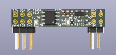
The STM8S001J3RS485 board is a tiny MODBUS node based on the STM8S001J3M3 "Low Density Value Line" STM8S µC in a SO8 package.

STM8S001J3RS485

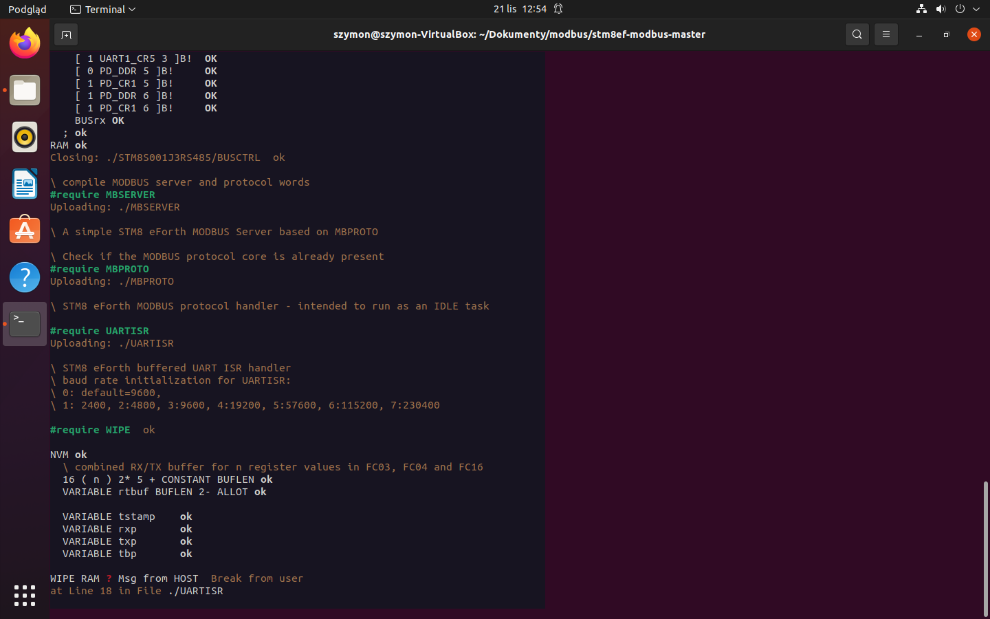
The code can be built and transferred to the devide by running make -f forth.mk BOARD=STM8S001J3RS485 flash. After flashing, the BUSCTRL file in the board configuration folder should be transferred using e4thcom and a 2-wire connection through PC5. After that, STM8S001J3RS485/board.fs can be transferred with #include.

MINDEV STM8S103F3 Breakout Board

It's easy to build custom targets, e.g. using the $0.80 MINDEV board, a cheap relay board, and an RS485 break-out board.

MINDEV

When using PB5 for RS485 direction control (-> BUSCTRL) the C0135 binary can be used right away (refer to the C0135 STM8 eForth Wiki page).

Supported MODBUS Function Codes

MBSERVER contains MODBUS function plug-ins with the following function codes (FC):

FC Description Support
1 Read Coils implemented
2 Read Discrete Inputs implemented
3 Read Holding Registers implemented
4 Read Input Registers implemented
5 Write Single Coil implemented
6 Write Single (Holding) Register implemented
15 Write Multiple Coils implemented
16 Write Multiple Registers implemented

Other FCs can be added (e.g., FC22 .. FC24).

A ready-to-use implementation for the C0135 relay board is implemented in C0135/board.fs. An example that shows how to develop minimal servers with FC handlers from scratch using the Forth console is in main.fs and, for different FCs, in the folder test.

Note that there is an experimental mapping of holding registers: holding register addresses from 60000 are mapped to the EEPROM. The mapping can be changed in the future. Community input on how to deal with MODBUS style register mapping is welcome.

For FC03, FC06 and FC15 the MODBUS address mapping is as follows:

MB address register MODBUS Forth
0 holding 1 holding
1 .. 59999 holding 2 holding 2+
60000 node ID $4000
60001 baud rate $4002
60002 .. 60319 user EEPROM $4004 - $43FE STM8S EEPROM

Installation

You can either use the binary release or build your own binary. This project uses the STM8 eForth "Modular Build" feature: make depend fetches the STM8 eForth release defined in the Makefile.

On a Linux system common dependencies are e.g. GAWK, MAKE and Python. SDCC needs to be installed. It's also possible to use tg9541/docker-sdcc in a Docker container (see details in the GitHub build workflow or refer to the Installation Instructions in the STM8EF-MODBUS Wiki).

The Getting Started section in the STM8 eForth Wiki provides an introduction to flashing STM8 eForth to a target µC.

Console

The STM8S UART is used by UARTISR for MODBUS RTU communication. The Forth console communicates through a half-duplex simulated RS232 two-wire interface on the PD1/SWIM GPIO pin. For communication with a standard USB-TTL converter only a diode is needed. Other CLI communication options are easy to implment, e.g. using simulated full-duplex RxD-TxD lines (e.g. using PA1 and PA2 after removing the C0135 8MHz crystal). It's also possible to use an STM8S High Density device with two UARTs, e.g. the STM8S207RBT6.

Please refer to the STM8 eForth Wiki to learn more about half-duplex CLI communication options and preferred terminal programs.

Architecture

The software architecture separates hardware abstraction and application in simple layers:

Layer Source file Description
6 main.fs or {BOARD}/board.fs configuration and application layer
5 MBSERVER MODBUS FC plug-ins (optional)
4 MBPROTO MODBUS protocol layer
3 UARTISR buffered UART communication
2 BUSCTRL bus access (i.e. RS485 direction control)
1 STM8 eForth lightweight interactive multi-tasking OS

The different concerns are separeted in the code and FC handlers can be changed through the CLI without restarting the application!

The code is organized in the following execution domains:

  • interrupt service routines for buffered MODBUS communication
  • fixed-rate background task for I/O logic (asynchronous to MODBUS)
  • foreground "idle mode" MODBUS protocol handler
  • foreground command line interface (CLI) through independent COM port provided by STM8 eForth
  • handlers for MODBUS I/O: mbpre for input, mbact for output actions

Please refer to the how-to in the wiki and don't hesitate to open an issue if you have questions!

stm8ef-modbus's People

Contributors

bademux avatar tg9541 avatar

Stargazers

 avatar  avatar  avatar  avatar  avatar  avatar  avatar  avatar  avatar  avatar  avatar  avatar  avatar  avatar  avatar  avatar  avatar  avatar  avatar  avatar  avatar  avatar  avatar  avatar  avatar  avatar  avatar  avatar  avatar  avatar  avatar

Watchers

 avatar  avatar  avatar  avatar  avatar

stm8ef-modbus's Issues

change node-id and baud without console

I have C0135 4-Relay Board.
Now i flash out/C0135/C135-forth.ihx with ST-LINK V2 and linux stm8flash.
Now have Node-ID 1 and 9600 baud.

I need change baud 19200 and Node-ID 4
If i send via USB to RS485 dongle 01 06 40 00 00 04 9D C9, then board reply 01 06 40 00 00 04 9D C9, bud Node ID is 1.
I try change baud to 19200, send 01 06 20 00 00 02 03 CB and reply is 01 06 20 00 00 02 03 CB. Baud is still 9600.

I try 01 06 00 00 00 04 88 09 bud Node-ID is not change.
How i change node id and baud without forth console?

Thanks

First transmission after reset may release the bus too early

While working on #44 it turned out that, under certain conditions, a MODBUS Server releases the bus after the second to last byte. The last byte won't be sent on the bus.

The following trace shows the UART TX in D1 and the RS485 transceiver direction in D2:

image

Support board "modbus_relay8"

A MODBUS board with the name "modbus_relay8 v1.2" arrived a few days ago:
image
It has an STM8S103K3T6C, an LM2596-5V switching power supply (7..30V, 2-3A), 8 relays and 8 insulated inputs. The usual price is at $15.

I made a Gist with Forth code for I/O based on SWIMCOM. GPIOs for I/O are documented in the code.

Other GPIOs traced so far are:

GPIO usage
PA1 Q (crystal not populated)
PA2 Q (crystal not populated)
PB6 S2 (key)
PB7 LED (not populated)
PD7 RS485 direction

New issue with modbus on STM8S103F3.

@TG9541 It is me again. I don't know how to reopen last issue so I created the new one. I sucessfully downloaded STM8S001J3.ihx as you recommended on my STM8S103F3 board. Then I wanted to upload modbus protocol from STM8S001J3RS485 file using halfduplex on PD5 pin but during compilation it stops on uploading WIPE RAM at line 18 in UARTISR file and I dont know why. Firstly I uploaded BUSCTRL and console shows ok. After #include STM8S001J3RS485/board.fs I have some problems. My purpose is to download modbus protocol on my board and then add temperature sensor and read temperature by modbus. Do you have any advice? Thank you very much in advance.
issue2

Improve FC>XT for some FC codes > FC16

Improve the implementation of FC>XT so that FC23 ("Read/Write Multiple Registers") and FC24 ("Read FIFO Queue") can be mapped into the 16 word FC-XT table. This shall be done with a simple hash that subtracts 11 from any FC number > 16.

The result is the following mapping which allows implementing all FCs customary in MODBUS-RTU (but not all at once):

FC Function FC-XT Table Index
1 Read Coils 0
2 Read Discrete Inputs 1
3 Read Multiple Holding Registers 2
4 Read Input Registers 3
5 Write Single Coil 4
6 Write Single Holding Register 5
7 Read Exception Status 6
8 Diagnostic 7
(9) invalid 8
(10) invalid 9
11 Get Com Event Counter 10
12 Get Com Event Log 11
(13) invalid 12
(14) invalid 13
15 Write Multiple Coils 14
16 Write Multiple Holding Registers 15
17 Report Server ID 6
(18) invalid 7
(19) invalid 8
20 Read File Record 9
21 Write File Record 10
22 Mask Write Register 11
23 Read/Write Multiple Registers 12
24 Read FIFO Queue 13

If needed FC43 (both "Read Device Identification" and "Encapsulated Interface Transport") can be implemented with the default handler

Use one buffer for receive and send

The MODBUS protocol is half duplex. This means that there is no need to have a dedicated transmit buffer. The RAM space is better used for one big buffer.

Update to STM8 eForth 2.2.27.pre2

STM8 eForth 2.2.27 version makes creating downstream projects a bit easier.

The most recent release uses Python3 for simload.sh and codeload.py.

Support MODBUS ASCII encoding

Some application require ASCII encoded MODBUS communication (e.g. MODBUS through telnet).
A MODBUS FC01 "Read Coils" request produced by a jamod test looks like this:

:010100020010EC<CR>

After this request, the receive buffer has the following content (hex):

3A 30 31 30 31 30 30 30 32 30 30 31 30 45 43 0D

Note that the MODBUS over Serial Line specification requires communication events to be terminated by <CR><LF>. The implementation should at least support <CR> but preferably also <CR><LF>.

Problems with uploading modbus files on STM8S103F3 board.

I am trying to do similar project like STM8S001JRS485 with modbus but using STM8S103F3 board and I can't upload modbus files on my board. I already downloaded on my board MINDEV.ihx using stm8flash but when I am uploading files in terminal some errors appear.
251473754_301563005126267_2181958665072965252_n
And this is my hardware:
254693199_279210360636572_1720134847936959929_n
Do you have any ideas how can I fix this ?
Thank you very much in advance.

Use bitfield addressing to improve FC-1 and FC-2

Bitfield read BF@ for Little Endian (LE, MODBUS) and write for BF! Big Endian (BE, STM8) was introduced in #19.

Generalize this to BF@ .,. BF! (BE) and LEBF@ ... LEBF! (LE) and use it for FC-1 (Read Coils) and FC-2 (Read Discrete Inputs).

Relays not switching

Hi Thomas,

I know pretty much next to nothing when it comes to eForth. I did not know what it was until a couple of days ago when I was trying to see if there would be a better firmware for the 4 relay board (it seems the newer ones have a "DAT" pin next to "SWIM" pin and are labelled "v1.2", mine has an STM8S003F3 on it).

Kudos for all the great work!

Now to my problem:
I have flashed the device and loaded the modbus files of this repo successfully after doing that diode mod.
My terminal application on the PC can talk to the device via a USB-RS485 adapter, but the "Write Single Coil" function is not activating the relays. Is there anything extra that needs to be done after the "make load" to get them working?

I don't think I will be diving too deep into eForth, I just needed a good reliable firmware that would respect the timings of modbus RTU the original firmware was completely ignoring.

Any ideas?

Remove obsolete files

Remove some obsolete files from the main branch:

  • improved versions of BF! an BF@ are now in the STM8 eForth lib/ folder
  • UARTASCISR will be removed (reopen issue #7 if there is demand for ASC transport)

Add C0135 Inputs

A simple implementation for reading C0135 inputs is needed. Like the original firmware, inputs should be low side (e.g. for reading NO switches or NPN proximity sensors).

Better implementation for "holding" register access

FC16 accesses holding registers in RAM from index 0 on. FC03 and FC06 act on EEPROM values from index 0 to 1023 and the holding variable in RAM from 1024 on. This needs to be fixed.

A MODBUSish way of doing things is using address ranges as a multiple of 10000. I guess that using holding registers in RAM (= process values) from 0 on and EEPROM from 10000 on (or higher) would be reasonable.

Add full board support for the STM8S001J3RS485 board

My intention now is to make the stm8s001rs485 hardware operate normally according to the modbus protocol you introduced. How do I proceed? Is there any related video operation that is helpful to me, thank you

use C0135 key "S2" for reset-to-defaults

Holding C0135 key "S2" during start-up or reset should set the EEPROM values for Node-ID and baud rate to default values:

  • Node-ID in EE_NODE ($4000) to 1 (holding register 0)
  • Baud rate in EE_BAUD ($4002) to 0 (default rate 9600, holding register 1)

Hint: the holding register addresses for EEPROM values are currently 0..n

Use DEFER-able dummy BUSCTRL as the default

The C0135 "4-Relay-Board" GPIOs were used as a default RS485 bus access. Implement a dummy bus access that can either be replaced in a "board configuration" or a default DEFER can be redirected with IS to a board specific routine.

FC05 addressing off-by-one

I finally noticed that FC05 encodes the address of "Coil 173" with "AC (Hex)". This means that my musings in #19 are factually wrong. Easy enough to fix, we're still in "alpha".

Allow configuration of µC variant and buffer size in UARTISR

Both µC variant and buffer size should be configurable and not hard coded in UARTISR. Take into account that e4thcom applies \res MCU: to a session, not to a file.

  • pre-defining BUFLEN should be possible (but it must stay within the "zero page" for now
  • use generic UART register names and make loading \res MCU: STM8S103 optional

Implement a minimal MODBUS-RTU Client

A review showed that implementing a very basic "MODBUS Client" based on UARTISR. The use case is application programming oriented and is thus very similar to writing application oriented MODBUS Servers (e.g., as described in the like in the README.md and sketched in the test folder).

The software architecture shall re-use the hardware layers and add just the minimum necessary for sending FC requests to a MODBUS server and receive and error-check the response. The application is responsible for implementing the required MODBUS Client FC encoders and decoders. An example application implementing reading and writing "Holding Registers" shall be provided.

The Architecture shall be as follows:

Layer Source file Description
6 clientapp.fs or {BOARD}/board.fs configuration and application layer
5 clientfc.fs MODBUS Client FC encoders and decoders
4 CLPROTO MODBUS Client protocol base
3 UARTISR buffered UART communication
2 BUSCTRL bus access (i.e. RS485 direction control)
1 STM8 eForth lightweight interactive multi-tasking OS

Recommend Projects

  • React photo React

    A declarative, efficient, and flexible JavaScript library for building user interfaces.

  • Vue.js photo Vue.js

    🖖 Vue.js is a progressive, incrementally-adoptable JavaScript framework for building UI on the web.

  • Typescript photo Typescript

    TypeScript is a superset of JavaScript that compiles to clean JavaScript output.

  • TensorFlow photo TensorFlow

    An Open Source Machine Learning Framework for Everyone

  • Django photo Django

    The Web framework for perfectionists with deadlines.

  • D3 photo D3

    Bring data to life with SVG, Canvas and HTML. 📊📈🎉

Recommend Topics

  • javascript

    JavaScript (JS) is a lightweight interpreted programming language with first-class functions.

  • web

    Some thing interesting about web. New door for the world.

  • server

    A server is a program made to process requests and deliver data to clients.

  • Machine learning

    Machine learning is a way of modeling and interpreting data that allows a piece of software to respond intelligently.

  • Game

    Some thing interesting about game, make everyone happy.

Recommend Org

  • Facebook photo Facebook

    We are working to build community through open source technology. NB: members must have two-factor auth.

  • Microsoft photo Microsoft

    Open source projects and samples from Microsoft.

  • Google photo Google

    Google ❤️ Open Source for everyone.

  • D3 photo D3

    Data-Driven Documents codes.