| Board | Support Status |
|---|---|
| ESP32-S3-BOX | NO |
| ESP32-S3-BOX-Lite | NO |
| ESP32-S3-BOX-3 | YES |
This project is developed based on Espressif's ESP32-S3-BOX-3 and ESP32-S3-USB-Bridge, aiming to create an open-source project that caters to both gaming controllers and remote control for model aircraft.
This guide will assist you in quickly getting started with ESP-JoyStick and provide all the detailed information about the project.
More information is on ESP32-S3-BOX-3-JoyStick.
This guide includes the following sections:
- Project Overview
- Hardware Reference
- Application Development
- Related Documentation
The ESP-JoyStick hardware system comprises the ESP32-S3-BOX-3 development board, JoyStick controller, and ESP32-S3-USB-Bridge receiver. The ESP32-S3-BOX-3 serves as the main controller, connecting to the JoyStick controller and ESP32-S3-USB-Bridge receiver through a PCIe interface. The system operates in "Game Mode" and "RC Remote Control Mode." In Game Mode, it supports USB-HID and BLE-HID protocols for computer gaming control, as well as an NES emulator mode. In RC Remote Control Mode, it utilizes the ESP-NOW wireless communication protocol to pair with ESP32-S3-USB-Bridge(Purchase link: TaoBao or Aliexpress) and other Espressif development boards(where the ESP32-S3-USB-Bridge or other Espressif development boards act as the model aircraft receiver), enabling wireless control of RC cars and ESP-Drone quadcopters.

ESP-JoyStick Overall Physical Diagram
- Game Mode:
- USB-HID Mode: Connect to the computer using a Type-C data cable, control computer games through the USB-HID protocol, and customize joystick and button functions.
- BLE-HID Mode: In this mode, the JoyStick is connected to the computer via Bluetooth using the BLE-HID protocol, enabling control of computer games with customizable joystick and button functions.
- NES Emulator Mode: In this mode, games from the NES emulator can be displayed on the screen of ESP32-S3-BOX-3.

ESP-JoyStick control computer games
- RC Remote Control Mode: ESP-JoyStick establishes a paired connection through the ESP-NOW wireless communication protocol with other Espressif official development boards (receivers) such as ESP32-S3-USB-Bridge. This enables wireless remote control for RC cars, ESP-Drone quadcopters, and other model aircraft.
ESP-JoyStick remote control the ESP-Drone
ESP-JoyStick control the RC car
To ensure that ESP-JoyStick has a comfortable grip, this project has optimized the PCB board shape and designed a matching 3D enclosure for it.
The following is a map of the main components of the ESP-JoyStick.

ESP-JoyStick Front
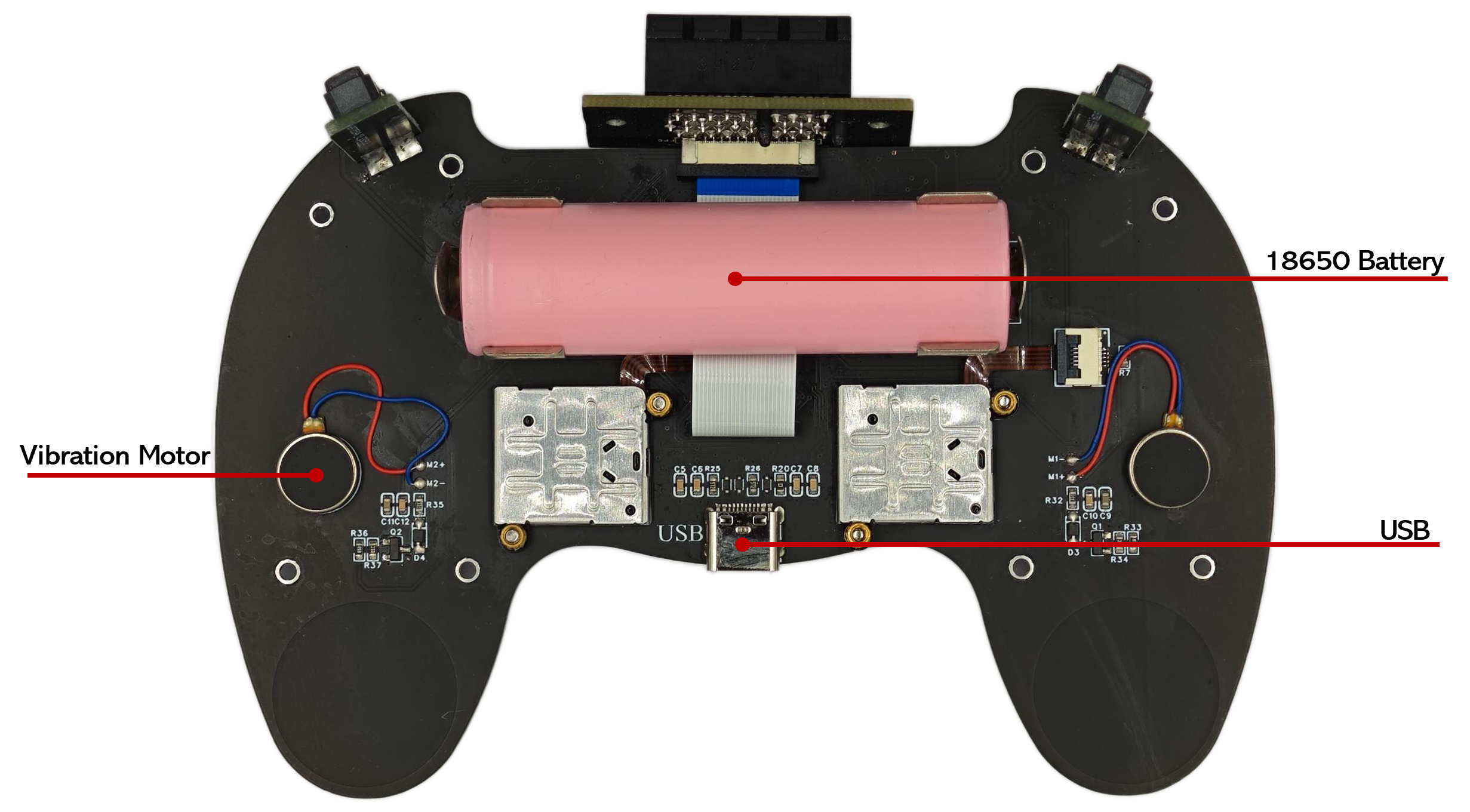
ESP-JoyStick Back
ESP-JoyStick has two joysticks. Each joystick, functioning similarly to a variable resistor, has varying resistance values at different positions. Utilizing the series voltage divider principle, the joystick's position can be inferred by detecting the voltage value. To capture the attitude, two ADC channels are used for each joystick. In addition to this, each joystick has a membrane button that developers can utilize.
ESP-JoyStick has a total of 16 physical buttons. Each button operates with a high logic level when not pressed and a low logic level when pressed. Due to the limited number of IO ports available on ESP32-S3-BOX-3, this project employs two 74HC165D parallel-to-serial shift registers. Developers can simulate SPI communication using three IO ports to read the status of all the buttons.
The vibration motor is controlled through a transistor (S8050). Developers simply need to configure one IO port as an output mode. When the port outputs a high logic level, the motor vibrates, and when it outputs a low logic level, the motor does not vibrate.
For specific pin assignments, please refer to the schematic diagram of ESP-JoyStick.
-
Schematic and PCB Source File:
