- Project details
- Compatibility
- Programming
- Operating instructions
- Frequently asked questions
- Building the firmware
- Translations
- Creating a .ioc file from scratch
- Additional Documentation
- Pending or non working features
If you liked the firmware, you can send me a beer with PAYPAL 🙂
Video of operation here: (Project in active development, the features will change continuously)
- This project started by forking PTDreamer's firmware. Since then it became a separate project.
- Developed on STM32Cube IDE. Basic configuration is easily done in CubeMx (Included in STM32Cube IDE).
- Unified codebase, different hardware support based on profiles, very few files need to be changed.
- Supports all display modes: I2C, SPI, software and hardware+DMA (When connected to hardware pins).
- Uses u8g2 graphics library.
- Dynamic screen loading to save RAM resources.
- Extremely customizable, lots of options available.
- Code highly optimized to avoid wasting cpu power, slow devices still run great.
The actual requirements are 10KB RAM and 64KB (*) flash.
(*) Currently the firmware has surpassed the 64KB limit, and uses the additional undocumented 64KB flash block.
(*) All 64KB devices have 128KB, with the 2nd 64KB block untested from the factory, so not guaranteed to work.
(*) To date, I have found zero issues. Original KSGER firmware also does this.
(*) ST-Link checks the written data, and the firmware uses checksums to protect the settings, any error will be detected.
CLONES Some controllers began to put stm32 clones due the chip shortage.
CKS32 works well, but MM32 and CH32 doesn't!
The CH32 almost works but the ADC makes strange things.
The MM32 is cortex-M0, but KSGER originally used STM32F10x (Cortex-M3), that's what this firmware uses, so it won't work at all.
If your board came with MM32 or CH32, replace it with a STM32F101/102/103.
The BOARDS folder has the board code profile, schematics and/or board pictures for quickly identify your hardware.
Currently supported controllers (Click to download the latest build):
- Quicko T12-072 : For STM32F072 variant. Current build is broken for this model, use this one.
- Quicko T12-103 For STM32F103 variant.
- KSGER v1.5 : Profile for STM32F103 (There are no other known CPUs used in this board).
- KSGER v2.x, JCD T12, T12-955, Handskit : Profile compatible with all STM32F101/2/3xx models.
- KSGER v3.x, T12-958 : Profile compatible with all STM32F101/2/3xx models.
For KSGER v2/v3: As long as use the correct firmware, any STM32 variant (101/102/103/C8/R8/CB/RB) will work.
Check Releases for downloads.
Actually, the easiest way to quickly identify your KGSER version is by looking at the Oled screen connection:
- 4 pin (I2C) = v2.x
- 6 pin (SPI) = v3.x
Also keep in mind that you can't trust the version shown in the original firmware to identify your board.
Go to BOARDS/... schematics folder and compare the pictures.
There are several compatible/cloned boards in the market that will work fine with Ksger profiles.
T12-951, T12-952, T12-956, T12-959 use STC mcu, not supported by this firmware.
First, make sure to read the Operating instructions!
You can check the commit history to see what have been changed between builds.
The original firmwares are available [HERE]
Some KSGER firmwares require an activation code which can be generated [HERE] [Alternative link]
Be warned, usually the MCU will be read-protected, so you won't be able to read its contents, only erase it.
The simplest way to not loose the original FW is actually to buy a new MCU, replace it, and store the original MCU in a safe place.
Any difference in the pinout will require firmware tuning, although one of the main proposits of this firmware is easing that.
There are some hacks / vulnerabilities that can be used to backup protected firmware, more details here:
STM32 power glitching timing attack
If the display has right/left line like this picture: Go to System menu / Offset and adjust the value until it's centered.

By default, never modify any PWM / Delay settings in the Iron menu. Doing so may cause such issues.
Also, new tips are often unstable, leading to temperature jumps.
Don't try to calibrate the tip in this state, neither set a high temperature, because it could go under control.
They usually settle after some burning time. It's recommended to set a medium temperature (250-300ºC) and leave like that for 15-20 minutes until it stabilizes.
If the temps are still unstable, try increasing the Iron/Delay option, allowing more time for the temp signal to settle.
A damaged, loose or defective connection in the handle will also cause this issues. Ensure the contacts are clean.
There have been problems with some board/stations like:
- Noisy power supply
- Broken / badly soldered capacitors
- Bad Op-Amp
- Bad 3v3 Regulator
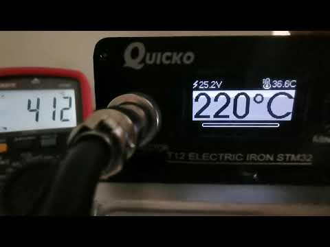
Buying a cheap high temperature meter is highly recommended!
These boards can have pretty different readings and tolerances. Even between T12 tips.
So the factory calibration is intentionally set lower than real, to avoid possible overheating problems.
Once you set the firmware, go to calibration and set there the real temperature measured with the external probe.
Ensure to read Calibration menu first!.
To calibrate, go into Calibration / Start.
Attach the temperature probe before proceeding!
If the difference between measured and real is higher than 50ºC, the calibration will be aborted, telling you to go into Calibration / Settings and manually adjust the values.
The calibration settings menu has 3 calibration steps: Zero set, 250 and 400°C.
When you edit 250/400ºC value, the power will be enabled and the value applied in real time, so be careful!
The power will be removed when no settings are being edited.
Adjust each value until it's close to the target temperature. Repeat for each step and save.
This values are only used by the calibration process, to prevent burning the tip if your board reads too low.
After adjusting, repeat calibration, this time it should work correctly.
The calibration results for the current tip can be seen in the tip settings menu.
Tip settings menu calibration values aren't meant to be another calibration menu, only for viewing (Ex. reporting calibration results) and for backup/restore purposes.
In the case you lose, wipe or reset the data, you can go back into that menu and adjust the values based on previous calibration results.
Zero calibration can't be manually restored, but it only takes few seconds to adjust.
Some amplifiers can introduce a small voltage offset that will translate into the cold tip reading 30-50°C higher than ambient temperature.
To fix that, enter the Calibration menu, insert a completely cold tip, enter Settings, adjust Zero set calibration and save.
After that, the offset will be compensated and the cold temperature will be normal.
It's highly recommended to recalibrate after changing this value.
Some KSGER controllers use a linear regulator to convert 24V to 3.3V, which is a very bad design and generates a lot of heat.
With the oled displays, each pixel turned on consumes more power, and this firmware uses much larger numbers for the display.
Thus, this firmware uses some more power. The design is so bad that the regulator will overload and shut down, resetting the board.
There're some options to fix this:
- Lower the display brightness to reduce the power consumption.
- Put a 100-150Ω 2W resistor in series with the regulator (24V->Resistor->LDO input). The resistor will drop part of the voltage and reduce the stress on the regulator.
- Replace the LDO with a better one, or modify the board, adding a LDO that accepts a small heatsink to take away the heat.
- Use a small DC/DC step-down module to convert 24V to 5V, and feed 5V to the 3.3V LDO (best option, barely makes any heat).
After fully reading the documentation, if you still have problems or doubts, please ask in the EEVblog thread:
https://www.eevblog.com/forum/reviews/stm32-oled-digital-soldering-station-for-t12-handle/
Video of building steps:

There's a new automated build script for Windows (_Building_script.bat) that allows a simple and fast way of copying and building the desired profile.
With it, all you need is to have CubeIDE installed in C:\ST... (It's the default installation folder), it will search and execute the tools without requiring any user intervention.
Just open it, choose your profile, and if you want to build it or not.
The compiled binaries will be placed in their respective BOARDS/... folders.
If you want to build your own, clone or download the source.
The source is stripped from ST own libraries and unnecesary stuff, only includes the very basic code owning to the project.
CubeMX will add the STM32 and CMSIS libraries automatically after a code generation.
Open the BOARDS folder, find your board (or take any to work with) and copy all the contents to the root of the project.
Open STM32CUBE IDE, click on Import/Existing project and select the project folder.
Important: Disable "Search for nested projects", select only the project in the root of the folder.
After that, double-click on [STM32SolderingStation.ioc] file:

CubeMX will open, then click on generate code:

After this, it'll be ready for compiling, click in the right arrow of the build button (Hammer icon) and select [Release]:

After a while you'll have the compiled bin/hex files inside Release folder.
If the build fails with files no found or undeclared functions errors, check the Include search path:
Right click on project -> [Properties] -> [C/C++ Build] -> [Settings] -> [Tool Settings] -> [MCU GCC Compiler] -> [Include paths]
Select [All configurations] in [Configuration] dropdown menu.
Now ensure these are present:
  /Core/Inc
  /Core/Src
  /Drivers/generalIO
  /Drivers/graphics
  /Drivers/graphics/gui
  /Drivers/graphics/gui/screens
  /Drivers/graphics/u8g2
  /Drivers/STM32Fxxx_HAL_Driver/Inc
  /Drivers/STM32Fxxx_HAL_Driver/Inc/Legacy
  /Drivers/CMSIS/Device/ST/STM32Fxxx/Include
  /Drivers/CMSIS/Include
(STM32Fxxx matches your current mcu family, ex. STM32F0xx, STM32F1xx)
If any is missing, click on Add... Select Workspace and select the missing ones.
You can make multiple selection while holding the Control key:

At some point, the firmware might not fit into the flash when compiling for debugging, as it'll skip optimizations, and use much more space.
In that case, you'll need to force some optimization level, starting with "Optimize for debug" (Og), and going to higher levels if still being too big (O1,O2,Osize).
The settings can be changed in project Properties / Build / Settings / MCU GCC Compiler / Optimizations.
However, when debugging, it's desirable to completely disable optimizations to see the program flow clearly.
If you had to enable any level of global optimizations, you can still selectively disable build optimizations for any function.
A line of code can be found at the start of main.h:
attribute((optimize("O0")))
Copy that line before a function to disable optimization, like this:
attribute((optimize("O0"))) void ThisFunctionWillNotBeOptimized(...)
If you want to retarget the project, avoid mixing different profile files.
Run the included script "Clean_Profile.bat", or manually delete these files:
/Core/Inc/*stm32*
/Core/Src/*stm32*
/Core/Src/system_stm32*
/Core/Startup/*
And then copy the board profile files overwriting any existing files.
If you use an existing project template and modify it, the changes must be reflected in /Core/Inc/board.h.
All the project code takes the data from there. The file it's pretty much self-explaining.
So, any changes you make in CubeMX, ex. use PWM timer6 intead timer2, or SPI1 instead SPI2...all that should be configured in their respective define.
As long as the GPIO names are called the same way, no further changes are needed.
For adding new languages, you have to modify these files:
- Src/settings.h
LANGUAGE_COUNT, lang_english,lang_xxxx in system_types enum - Drivers/gui/gui_strings.c
strings_t strings, Langs[LANGUAGE_COUNT]
For adding new characters to the existing fonts symbols, there're some instructions here:
- Drivers/graphics/u8g2/tools/font/bdfconv/Notes.txt
- I2C eeprom. Some boards have it, some doesn't. So internal flash storage is used for all.
Also, the current settings don't fit in the commonly used 24C08 memory. - RTC clock. There's very little space in the screen. Use it for what matters, instead for showing a clock!
- Dreamcat4 has made a great research and documentation of T12 and STM32 related stuff:
- Dreamcat4 documentation repo
- Backup of original PTDreamer Blog


