Giter VIP home page Giter VIP logo

voron-switchwire's Introduction

Voron Switchwire

CLICK HERE TO DOWNLOAD

The above link includes the stealthburner toolhead files which are compatible with several of the printers in the Voron lineup. To keep things organized, StealthBurner’s files are maintained separately. the Stealthburner Repository can be browsed by clicking HERE

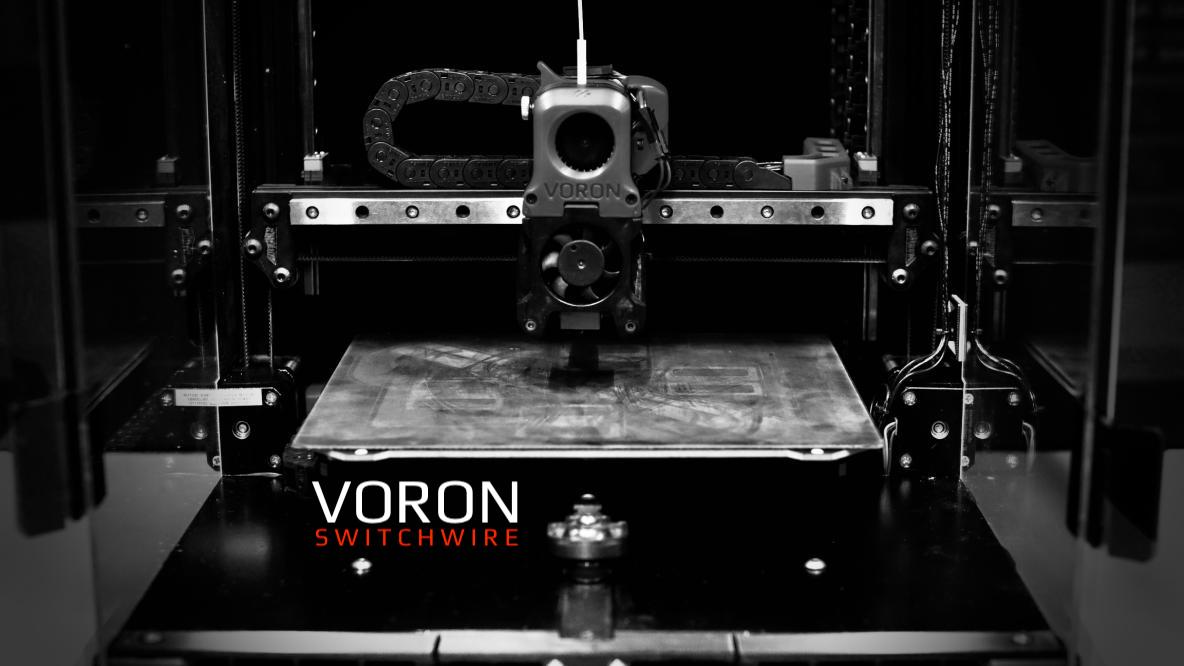
Image of Voron Switchwire

The official release of the Voron Switchwire 3d printer. You can find the BOM and any other relevant information at the Voron Design website.

Voron Logo

voron-switchwire's People

Stargazers

 avatar  avatar  avatar  avatar  avatar  avatar  avatar  avatar  avatar  avatar  avatar  avatar  avatar  avatar  avatar  avatar  avatar  avatar  avatar  avatar  avatar  avatar  avatar  avatar  avatar  avatar  avatar  avatar  avatar  avatar  avatar  avatar  avatar  avatar  avatar  avatar  avatar  avatar  avatar  avatar  avatar  avatar  avatar  avatar  avatar  avatar  avatar  avatar  avatar  avatar  avatar  avatar  avatar  avatar  avatar  avatar  avatar  avatar  avatar  avatar  avatar  avatar  avatar  avatar  avatar  avatar  avatar  avatar  avatar  avatar  avatar  avatar  avatar  avatar  avatar  avatar  avatar  avatar  avatar  avatar  avatar  avatar  avatar  avatar  avatar  avatar  avatar  avatar  avatar  avatar  avatar  avatar  avatar  avatar  avatar  avatar  avatar  avatar  avatar  avatar

Watchers

 avatar  avatar  avatar  avatar  avatar  avatar  avatar  avatar  avatar  avatar  avatar  avatar  avatar  avatar  avatar  avatar  avatar  avatar  avatar  avatar  avatar  avatar  avatar  avatar  avatar  avatar  avatar  avatar  avatar  avatar  avatar  avatar  avatar  avatar  avatar  avatar  avatar  avatar  avatar  avatar  avatar  avatar  avatar  avatar

voron-switchwire's Issues

Number of USB Cable A-male B-male

The BOM indicates

USB Cable A-male B-male QTY: 2

The sourcing guide indicates

USB Cable A-male Mini B-male (Included with SKR Mini) QTY: 1

latch_shuttle.stl needs an [a] tag

This part is red in the CAD and also in the V2.4 manual, it doesn't really matter in the end since it's not visible, but I figured I'd let y'all know anyway.

Incorrect / Old Klipper Configs.

After a full month of testing and fine tuning i made a Correct fysetc spider printer.cfg.
The old firmware are a very old Klipper config. Also extruder settings are incorrect. That is causing extreme heat Extruder Motor.
Here is my Printer.cfg for the fysetc spider

https://pastebin.com/VuUeXtPq

#####################################################################

Printer settings

#####################################################################
[mcu]
serial: /dev/ttyAMA0
restart_method: command

[printer]
kinematics: corexz
max_velocity: 200
max_accel: 4000
max_accel_to_decel: 4000
max_z_velocity: 50
max_z_accel: 1000
square_corner_velocity: 4.0

[input_shaper]
shaper_freq_x: 52
shaper_freq_y: 54.5
shaper_type: mzv

[stepper_x]
step_pin: PE11
dir_pin: !PE10
enable_pin: !PE9
endstop_pin: ^PB14
position_endstop: 250
position_min: 0
position_max: 250
homing_speed: 70
homing_positive_dir: true
rotation_distance: 40
full_steps_per_rotation: 200
microsteps: 16

[tmc2209 stepper_x]
uart_pin: PE7
run_current: 0.5
hold_current: 0.3
interpolate: True
stealthchop_threshold: 250

[stepper_y]
step_pin: PD8
dir_pin: !PB12
enable_pin: !PD9
endstop_pin: ^PB13
position_endstop: 250
position_min: 0
position_max: 250
homing_speed: 70
homing_positive_dir: true
rotation_distance: 40
full_steps_per_rotation: 200
microsteps: 16

[tmc2209 stepper_y]
uart_pin: PE15
run_current: 0.6
hold_current: 0.4
interpolate: True
stealthchop_threshold: 250

[stepper_z]
step_pin: PD14
dir_pin: !PD13
enable_pin: !PD15
endstop_pin: probe:z_virtual_endstop
position_max: 235
homing_speed: 40
position_min: -3.0
rotation_distance: 40
full_steps_per_rotation: 200
microsteps: 16

[tmc2209 stepper_z]
uart_pin: PD10
run_current: 0.5
hold_current: 0.3
interpolate: True
stealthchop_threshold: 250

[bed_mesh]
speed: 150
horizontal_move_z: 10
mesh_min: 25,35.0
mesh_max: 225.0,220
probe_count: 6,6
algorithm: bicubic
fade_start: 1
fade_end: 10
fade_target: 0

[probe]
pin: PA3
x_offset: 0.0
y_offset: 25.0
#z_offset: 0
speed: 40.0

[homing_override]
axes: z
set_position_z: 0
gcode:
G90
G0 Z5 F500
G28 X0 Y0
G0 X125 Y100 F9000
G28 Z0
G0 Z5 F500

#####################################################################

Extruder

#####################################################################

E0 on MCU X/Y

[extruder]
max_extrude_only_distance: 1000.0
step_pin: PD5
dir_pin: !PD6
enable_pin: !PD4

Update value below when you perform extruder calibration

If you ask for 100mm of filament, but in reality it is 98mm:

rotation_distance = <previous_rotation_distance> * <actual_extrude_distance> / 100

22.6789511 is a good starting point

rotation_distance: 22.225372078 #Bondtech 5mm Drive Gears

Update Gear Ratio depending on your Extruder Type

Use 50:17 for Afterburner/Clockwork (BMG Gear Ratio)

Use 80:20 for M4, M3.1

gear_ratio: 50:17 #BMG Gear Ratio
microsteps: 16
full_steps_per_rotation: 200 #200 for 1.8 degree, 400 for 0.9 degree
nozzle_diameter: 0.400
filament_diameter: 1.75
heater_pin: PB15

Validate the following thermistor type to make sure it is correct

sensor_type: ATC Semitec 104GT-2
sensor_pin: PC0
min_temp: 10
max_temp: 270
max_power: 1.0
min_extrude_temp: 170
control = pid
pid_kp = 26.213
pid_ki = 1.304
pid_kd = 131.721

Try to keep pressure_advance below 1.0

pressure_advance: 0.05

Default is 0.040, leave stock

pressure_advance_smooth_time: 0.040

E0 on MCU X/Y

Make sure to update below for your relevant driver (2208 or 2209)

[tmc2209 extruder]
uart_pin: PD7
interpolate: false
run_current: 0.45
hold_current: 0.30
sense_resistor: 0.110
stealthchop_threshold: 0

#####################################################################

END Extruder

#####################################################################

#####################################################################

Probe Settings

#####################################################################

Textured Bed

#[probe]
#z_offset = 4.910

Flat Bed

[probe]
z_offset = 4.740

#####################################################################

End Probe Settings

#####################################################################

[heater_bed]
heater_pin: PB4
sensor_type: NTC 100K MGB18-104F39050L32
sensor_pin: PC3
control = pid
pid_kp = 60.695
pid_ki = 1.073
pid_kd = 858.069
min_temp: 0
max_temp: 130

#######################################

Enclosure Temp Sensor Section

#######################################
[temperature_sensor enclosure_temp]
sensor_type: NTC 100K beta 3950
sensor_pin: PC1
min_temp: 0
max_temp: 100
gcode_id: C

#######################################

Raspberry Temp Sensor Section

#######################################
[temperature_sensor Pi]
sensor_type: rpi_temperature
min_temp: 0
max_temp: 90

[fan]
pin: PB2

thermally controlled hotend fan

[heater_fan my_nozzle_fan]
pin: PB1
max_power: 1.0
kick_start_time: 0.100
heater: extruder
heater_temp: 50.0
fan_speed: 1.0

[virtual_sdcard]
path: ~/gcode_files

#####################################################################

Displays

#####################################################################

[display]

mini12864 LCD Display

lcd_type: uc1701
cs_pin: PC11
a0_pin: PD2
rst_pin: PC10
encoder_pins: ^PC6,^PC7
click_pin: ^!PA8
contrast: 63
#spi_bus: spi1
spi_software_mosi_pin: PA7
spi_software_miso_pin: PA6
spi_software_sclk_pin: PA5

[neopixel fysetc_mini12864]

To control Neopixel RGB in mini12864 display

pin: PC12
chain_count: 3
chain_count: 60
initial_RED: 0.1
initial_GREEN: 0.5
initial_BLUE: 0.0
color_order: RGB

Set RGB values on boot up for each Neopixel.

Index 1 = display, Index 2 and 3 = Knob

[delayed_gcode setdisplayneopixel]
initial_duration: 1
gcode:
SET_LED LED=fysetc_mini12864 RED=1 GREEN=0 BLUE=0 INDEX=1 TRANSMIT=0
SET_LED LED=fysetc_mini12864 RED=1 GREEN=0 BLUE=0 INDEX=2 TRANSMIT=0
SET_LED LED=fysetc_mini12864 RED=1 GREEN=0 BLUE=0 INDEX=3

#####################################################################

LED Control

#####################################################################

Chamber Lighting

[output_pin caselight]
pin: PB3
#max_power: 1.0
#kick_start_time: 0.5
pwm: true
shutdown_value: 0
value: 100
cycle_time: 0.01
scale: 100

Lighting Control

[gcode_macro lights_off]
gcode:
SET_PIN PIN=caselight VALUE=0

[gcode_macro lights_on]
gcode:
SET_PIN PIN=caselight VALUE=100

#####################################################################

End LED Control

#####################################################################

#####################################################################

Macros

#####################################################################
[display_status]

[pause_resume]

[gcode_macro CANCEL_PRINT]
rename_existing: BASE_CANCEL_PRINT
gcode:
M107
TURN_OFF_HEATERS
DISABLE_MOTORS
CLEAR_PAUSE
SDCARD_RESET_FILE
BASE_CANCEL_PRINT

[gcode_macro PAUSE]
rename_existing: BASE_PAUSE
gcode:
SAVE_GCODE_STATE NAME=PAUSE_state
BASE_PAUSE
G91
G1 E-1.7 F2100
G90
_PARK_HEAD

[gcode_macro RESUME]
rename_existing: BASE_RESUME
gcode:
G91
G1 E1.7 F2100
G91
RESTORE_GCODE_STATE NAME=PAUSE_state MOVE=1
BASE_RESUME

[gcode_macro DISABLE_MOTORS]
gcode:
M18

[gcode_macro PRINT_START]
gcode:
lights_on
M117 Homing...
M140 S{BED_TEMP} ; set bed final temp
M104 S{EXTRUDER_TEMP} ; set extruder final temp
M190 S{BED_TEMP} ; wait for bed final temp
M109 S{EXTRUDER_TEMP} ; wait for extruder final temp
BED_MESH_CLEAR

G21 ; set units to millimeters
G90 ; use absolute coordinates
M83 ; use relative distances for extrusion
G28 ; home all axes
G1 Z20 F3000                   ; move nozzle away from bed
BED_MESH_CALIBRATE
G92 E0
G90
G0 X13 Y13 F6000
G0 Z0.4
G91
G1 X120 E30 F1200
G1 Y1
G1 X-120 E30 F1200
G92 E0
G90
G1 Z20.0 F3000
G92 E0
M117 Printing....

[gcode_macro PRINT_END]

Use PRINT_END for the slicer ending script - please customise for your slicer of choice

gcode:
M400 ; wait for buffer to clear
G92 E0 ; zero the extruder
G1 E-1.0 F3600 ; retract filament
G91 ; relative positioning
G0 Z1.00 X20.0 Y20.0 F20000 ; move nozzle to remove stringing
TURN_OFF_HEATERS
M107 ; turn off fan
G1 Z50 F3000 ; move nozzle up 20mm
G90 ; absolute positioning
G0 X0 Y220 F3600 ; park nozzle at rear
BED_MESH_CLEAR
M117 Finished!
lights_off

#####################################################################

End Macros

#####################################################################

## <---------------------- SAVE_CONFIG ---------------------->
#
# DO NOT EDIT THIS BLOCK OR BELOW. The contents are auto-generated.
#*#

Filler text on manual page 120

In the PDF docs on page 120, in a caption about premade cables there is filler text instead of a description of the cables.

The filler text is

Uptis velicatur sequam sunte
voloresed magnisit inihit,
ommodicia vit ad quis maio.

Y-CARRIAGE

where are you find y carriage cad file ?

Build guide of some sorts?

Maybe I'm blind but i've searched for build guides or how to's or anything close to that and i couldn't find one? is it still on the to-do?

Purge line g code causing issue during print start.

Using the switchwire skr mini e3 v3 config file and superslicer with PRINT_START in the start gcode after print start having the Purge Line Gcode uncommented I get error:
Extruder not hot enough: If I manually preheat before PRINT_START I do not get this line.
7:15 AM
Move out of range: 5.000 5.000 3.000 [0.000]
7:15 AM
Move out of range: 5.000 5.000 3.000 [0.000]
If I comment it out it prints normally.
Uncommenting This..
##Purge Line Gcode
G92 E0;
G90
G0 X5 Y5 F6000
G0 Z0.4
G91
G1 X120 E30 F1200;
G1 Y1
G1 X-120 E30 F1200;
G92 E0;
G90
klippy.log

Manual only shows Probe Signal Wire Connection, Website is also unclear

The Switchwire manual shows the diode and signal wire connection but just shows the positive and negative probe wires going to nothing.
Screenshot from 2022-03-08 16-31-28

The website could be more clear as well.
https://docs.vorondesign.com/build/electrical/sw_miniE3_v20_wiring.html
Says...
Plug Probe GND and Signal (with BAT85 diode) in to Z-STOP
Connect Probe +V to VIN in terminal next to HB

Sound Say...
Plug Probe Ground (Blue Wire) to Z-STOP GND and Signal (Black Wire) with BAT85 diode (black band facing away from connector) in to Z-STOP PC2
Connect Probe Positive (Brown Wire) to POWER 12/24V (The one just to the Left of BED)

Wich configuration for Swichtwire withg SKR 1.3

Hi there,

so i bought a used switchwire with an skr 1.3 and a pi 4 b.

The problem is the printer has no firmware on the sd card of the skr.

So i tought taht seeting it up completly new would solve this.

But i am stuck at the point of the voron instructions for selecting the software config out of the three ones.

My skr 1.3 board is not listed ?

Would be awsome if someone could help.

Thanks for your time.

Inconsistencies between BOM and Sourcing Guide

There are inconsistencies between the sourcing guide https://vorondesign.com/sourcing_guide?model=VS and the BOM available on the https://vorondesign.com/voron_switchwire page

Under the Misc section in the sourcing guide there is
BMG Extruder Hardware Kit
In the downloadable BOM this is listed in the Motion section as
BMG Extruder Componnets Kit

Under the Motion section in the sourcing guide there is
Key-bak Super48 13oz
this is listed in the Misc section in the downloadable BOM as
Key-Bak Super 48 Retractable Keychain
(I think this description is clearer as to what the item is)

Bearing block for SW unnecessary?

[a]_x_bearing_block_SW_beta0.stl is only used for SW, but the V2/Trident MGN12 carriage can mount to the same rail without this extra piece.

I suggest changing the SW carriage to mount directly to the rail, the same as V2/Trident. This would save an extra part, 4 screws, and 4 heat set inserts. I was able to redesign the original SW carriage in this way and have used it without issues.

Maybe I am missing an advantage of the extra block, but I suspect it exists simply because it was designed first. When Trident was designed, a better way to make the carriage was discovered.

Update printer to remove endstop_position from [stepper z]

20201213: It is not valid to specify a Z "position_endstop" when using "probe:z_virtual_endstop". An error will now be raised if a Z "position_endstop" is specified with "probe:z_virtual_endstop". Remove the Z "position_endstop" definition to fix the error.

about MOS for sw

It says you need two MOSs in BoM, but it's not written in the sourcing guide. Do I have to buy MOS? How can I connect if I need MOS or not?

Several files have been updated but there's no new release

I'm currently building a Switchwire and downloaded the latest Release from 28 of August in 2020. While printing the parts, I realized that an old version of the Afterburner is included in this release. A closer look into the repository unveiled that several STLs have been updated after this release. I think there should be a "Switchwire 1.1" or "Switchwire 1.0.1" release for that. At least the update of the Afterburner would have been worth it after all. People have been downloading an outdated release to build the switchwire for a year and a half now....

Assembly Manual repeats

In the Assembly manual, pages 74 and 75 for the Clockwork assembly are repeated, overwriting the instructions for the guidler and latch install.

The connector cover on directfeed is incompatiable with generic steppers

I'm not sure which connector cover in the afterburner repo is the one in switchwire.

I got this wacky stepper motor from Taobao. With this motor, the following issues would occur:

  • The cable cover will break in the installation
  • The 20mm screws are to be too short to reach the threads
  • The threaded insert on the clockwork can't be used to secure the cable cover since it's further away.

The image below is the stepper:
IMG_3633

BOM Electronics vs Sourcing Guide Electronics

The downloadable BOM has an Electronics section with 20 items.

The sourcing guide has an an Electronics section with 13 items.

The sourcing guide has a "Controller" section with 6 items which the downloadable BOM does not have
some of these items can be found in the Electronics section of the dowloadable BOM
for example
SKR Mini E3 V2
but others are not listed in the BOM at all for example
MicroSD Card

New printhead

hello,i'll like to use a Biqu H2 extruder on this,but cannot find a mount plate compatible

Belt clamp Switchwire orientation

I think the orientation of the [a]_Belt_Clamp_SW_x2.STL is wrong and should be rotated the same as the [a]_xz_belt_clip_x2.stl in the Switchwire-github.

Recommend Projects

  • React photo React

    A declarative, efficient, and flexible JavaScript library for building user interfaces.

  • Vue.js photo Vue.js

    🖖 Vue.js is a progressive, incrementally-adoptable JavaScript framework for building UI on the web.

  • Typescript photo Typescript

    TypeScript is a superset of JavaScript that compiles to clean JavaScript output.

  • TensorFlow photo TensorFlow

    An Open Source Machine Learning Framework for Everyone

  • Django photo Django

    The Web framework for perfectionists with deadlines.

  • D3 photo D3

    Bring data to life with SVG, Canvas and HTML. 📊📈🎉

Recommend Topics

  • javascript

    JavaScript (JS) is a lightweight interpreted programming language with first-class functions.

  • web

    Some thing interesting about web. New door for the world.

  • server

    A server is a program made to process requests and deliver data to clients.

  • Machine learning

    Machine learning is a way of modeling and interpreting data that allows a piece of software to respond intelligently.

  • Game

    Some thing interesting about game, make everyone happy.

Recommend Org

  • Facebook photo Facebook

    We are working to build community through open source technology. NB: members must have two-factor auth.

  • Microsoft photo Microsoft

    Open source projects and samples from Microsoft.

  • Google photo Google

    Google ❤️ Open Source for everyone.

  • D3 photo D3

    Data-Driven Documents codes.