Giter VIP home page Giter VIP logo

lilygo-t-sim7000g's Introduction

LilyGo SIM7000G

Two main versions of the LilyGo SIM7000G have been released with the current board having better power management than the old board.

Version 20200415

This board is an improvement of the original with fixes added that where recommended from feedback.

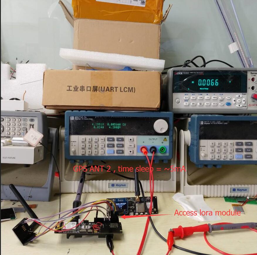
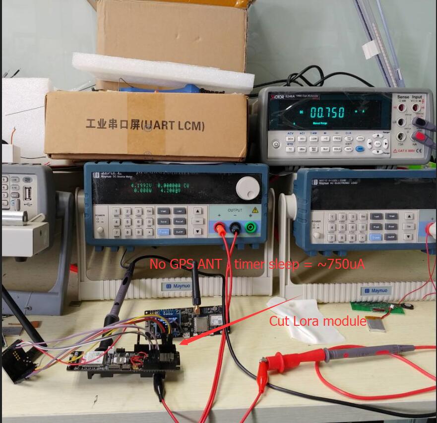
  1. Added active GPS antenna power control, when the module GPIO4 is not turned on the antenna consumes only the static current of the LDO.
  2. Replaced TP4056 with CN3065 for solar charge input management.
  3. Added reverse battery protection
  4. Added battery overcharge protection
  5. Added battery over-discharge protection

Version 20191227

First board release,Sales have been stopped.

Product 📷:

Examples Product Link Schematic Status
Version 20200415 (点击查看) Aliexpress/Amazon USA/FR/DE New Version
Version 20191227 (点击查看) Obsolete Old Version

Notes for new Users

  1. SIM7000/SIM707G does not support 4G network. Please ensure that the USIM card you use supports 2G(GSM)/NB-IOT access,SIM7070 positioning and cellular cannot be used simultaneously. Please disconnect the network when positioning, and turn off GPS when connecting to the network

  2. pin VIN is a USB input, if a battery is being used to power the device there will be no voltage output from VIN meaning 3.3v is the only power output.

  3. When using the built-in battery pack the on/off switch will function as normal, supplying/cutting off power to the board, However, if an external battery pack is used and attached to the VBAT pin the on/off switch will be bypassed meaning the only way to shut off will be to disconnect the batteries.

  4. On/off switch is for battery use only, it will not function when plugged into USB.

  5. Battery voltage can not be read when plugged into USB using the onboard BAT ADC(35)

  6. Recommended solar panels are 4.4v to 6v DO NOT EXCEED OR BOARD MAY BE DAMAGED

  7. When an SD card in you can not upload software in Arduino IDE since the SD card uses IO2 as CS, the SD card must be removed when uploading a new sketch.

  8. On Version 20200415, When using GPS the SIM7000G(GPIO4)/SIM7070G(GPIO5)(Physical pin number 48) needs to be set to HIGH to enable the antenna modem.sendAT("+CGPIO=0,48,1,1"); once finished the pin can be set LOW modem.sendAT("+CGPIO=0,48,1,0"); to prevent power leaking to the GPS antenna, This will make help battery life. If using USB or battery life is not a concern, it can be left HIGH.

  9. If you are unable to access the network, please try <examples/Arduino_NetworkTest>, which will test the network connection. There are also binary files in the firmware directory, you can use the Flash Download Tools to download.

  10. How to change the connection method?

  • For example, the Arduino_TinyGSM/AllFunctions.ino , you only need to change modem.setNetworkMode(38); to the corresponding number, and your network access speed depends on the carrier of the SIM card you use. Before using it, you can communicate with the operator of your SIM card.
  • The effect is as follows:
  1. The initial network registration may be slow. Please be patient. You can configure the locked band as shown in the following figure.

  2. How to update firmware?

  1. When the onboard USB bridge cannot be downloaded, you can use the external USB bridge to upload the sketch

lilygo-t-sim7000g's People

Contributors

lewisxhe avatar lilygo avatar mr-haleya avatar

Stargazers

 avatar  avatar  avatar  avatar  avatar  avatar  avatar  avatar  avatar  avatar  avatar  avatar  avatar  avatar  avatar  avatar  avatar  avatar  avatar  avatar  avatar  avatar  avatar  avatar  avatar  avatar  avatar  avatar  avatar  avatar  avatar  avatar  avatar  avatar  avatar  avatar  avatar  avatar  avatar  avatar  avatar  avatar  avatar  avatar  avatar  avatar  avatar  avatar  avatar  avatar  avatar  avatar  avatar  avatar  avatar  avatar  avatar  avatar  avatar  avatar  avatar  avatar  avatar  avatar  avatar  avatar  avatar  avatar  avatar  avatar  avatar  avatar  avatar  avatar  avatar  avatar  avatar  avatar  avatar  avatar  avatar  avatar  avatar  avatar  avatar  avatar  avatar  avatar  avatar  avatar  avatar  avatar  avatar  avatar  avatar  avatar  avatar  avatar  avatar  avatar

Watchers

 avatar  avatar  avatar  avatar  avatar  avatar  avatar  avatar  avatar  avatar  avatar  avatar  avatar  avatar  avatar  avatar  avatar  avatar  avatar  avatar  avatar  avatar  avatar  avatar  avatar  avatar  avatar  avatar

lilygo-t-sim7000g's Issues

Use Cat-M1?

So it appears that all the examples use GPRS?
We couldn't find any examples using 4G, LTE, or Cat-M1.
From what I have read and been told GPRS is 2g (or sometimes called 2.5G). Our State is ending all 2G support very soon and 3G will follow quickly after. We have been trying to find a way to use Cat-M1 with the TTGO sim7000g but could not find any documents explaining how. The SIM7000G documentation shows that it supports the Cat-M1 protocol.

Is a special sim card required to use Cat-M1? How do you know if you are connected over Cat-M1 and not 2G? Is this even supported by any available libraries?

Any help with this would be greatly appreciated.

We posted this and an issue because we are having issues with getting it to work and found no examples using it.

Fail to Attach service

Hi Team,

First of all I am new in LilyGO-T-SIM7000G / Arduino world.

Unfortunately I am unable to use the board. I am getting the following error: "Fail to Attach service".
I would like to know if this a network operator error or I am doing something wrong?

I am charging the board at USB. The green and blue leds are always opened while the red led is blinking.

Thanks in advance!
Adrian
error

SIM7000 nRESET overvoltage protection

The nRESET pin on the SIM7000 has a maximum input voltage of slightly over 2 volts. The GPIO5 pin from the ESP32 can go as high as 3.3 volts. Several options exist. The first is to put a diode between the SIM7000 RESET pin and the rest of the circuit. The second is to simply disconnect the pin completely from the circuit. The SIM7000 hardware manual states "Note: This function is only used as an emergency reset. The RESET pin will be ineffectiveness in the power off mode.". I've been testing several SIM7000 modules without ever needing to use the reset feature. The third option is to leave the circuit as-is but state BOLDLY to configure the ESP32 GPIO5 as OUT_OPEN_DRAIN!
Personally I prefer option 2. And it frees up a pin on the ESP32 which could possibly be used to switch power on & off to the GPS antenna circuit. See my entry in the "Deep sleep power consumption" thread.

Zener protection diode for U13.

U13 (CN3065) has a rated max voltage of 6v (and an absolute max of 6.5v). D3, the zener protection diode for it is 6.8v. Will that be updated to a 5.6v 5% or 10% zener?

What are the different types????

Ok so now I have 3 different boards that have shown up at my house... I have a 20191211 a 20191227 and a 20-4-15. WHATS THE DIFFERENCES???? and why is there no documentation showing different types and new/removed futures???

Seriously post some documentation explaining these! or even explain it to me and ill make a PR idc but people need to know this stuff. also, (issue #22) schematics and dimensions are different so that needs to be updated as well.

@lewisxhe @nikil511 @ROSW6341 You three seem like the best to answer this question...

ttgo sim7000g does not go to sleep

Hello, I am trying to sent the ttgo to sleep, here is my code.

int i = 10;
	while (i) {
		SerialGSM.println("AT+CGNSPWR=0");																				//GNSS Power on
		delay(500);
		if (SerialGSM.available()) {
			String r = SerialGSM.readString();
			Serial.println(r);
			if ( r.indexOf("OK") >= 0 ) break;;
		}
		delay(500);
		i--;
	}																													Serial.println("internal GPS power DOWN");
	
	i = 10;
	while (i) {
		SerialGSM.println("AT+SGPIO=0,4,1,0");														Serial.println("GNSS pin DOWN");
		delay(500);
		if (SerialGSM.available()) {
			String r = SerialGSM.readString();
			Serial.println(r);
			if ( r.indexOf("OK") >= 0 ) break;;
		}
		delay(500);
		i--;
	}
	
	
	//delay(1000);
	
	
	digitalWrite(PIN_DTR, HIGH);																						Serial.println("MODEM DOWN");
	delay(1000);
	
	
	i = 10;
	while (i) {
		SerialGSM.println("AT+CSCLK=1");																				//modem power down
		delay(500);
		if (SerialGSM.available()) {
			String r = SerialGSM.readString();
			Serial.println(r);
			if ( r.indexOf("OK") >= 0 ) break;;
		}
		delay(500);
		
		i--;
	}


	digitalWrite(EXTERNAL_PWR_PIN, LOW);																				Serial.println("External Sensor DOWN");
																														Serial.println("GOING to SLEEP NOW");
    
    
	esp_deep_sleep_start();

I Expect this to send the system to draw less than 10 mA current. However, the Modem lights both stay on (the network activity light flashes some times), and i draws more than 40 mA, or sometimes even 200 mA current.

What am I doing wrong?

Does not recover after battery dies

I am using the latest version of the board and have an external battery pack of 18650s that are wired in series attached to the vbat pin and ground. I am using in mppt solar charger to charge the battery pack that is attached because the onboard solar charger has too tight of voltage tolerance.

I have been using it without any problems for months, during the day the charger charges the batteries and at night the batteries keep everything going.

Anyways, I wanted to do a test to see what would happen if the solar panel got covered in dirt or if it rained for a week. I disattached the solar panel and let the batteries drain until the board shut off. When I measure the battery's voltage they were at 1.7 volts which I expected they would be lower than the 2.5 volt cut off because I have an external sensor attached that can draw voltage all the way down to 1.7 volts... I then reattached the solar panel and left it charging in the sun. After about six hours I was getting suspicious since I had not seen any new data up here on my graphs. I went outside and check the voltage of the batteries and they were at 3.7 volts but the SIM 7000 status LEDs were off.

The blue LED was on and solid. my sketch shuts the blue LED off after boot to save some power. No other LEDs were on except the blue one. I press the power button and nothing happened I was only able to get it to recover by pressing the reboot button.

I need these boards to be able to recover after batteries died and are recharged. Is this a known issue? could it be caused because I am using an external battery pack connected to the vbat pin and gnd instead of the positive / negative terminal of the battery connector that is on the back of the board? Does the board have any kind of circuitry that is supposed to have it recover such incidents? Or can it be added?

New version of hardware discussion

In the previous version of SIM800L, many customers have put forward many good suggestions, so in the 7XXX version, the schematics are released first. Please give suggestions. We will adopt good comments in the new version of SIM7XXX series. Whether the chip is 7000G or 7600G, I will choose which one is the main chip in the following two replies.

Major changes regarding the new version:

  1. Add TP4056 as the main power chip and as a solar charge management chip
  2. Change the lithium battery to 18650 battery
  3. Add SD card slot

Welcome to make suggestions, thanks
SIM7000X.pdf

Modem of module not responding on AT commands

Hello,
I bought this module for tests and at the beginning everything was fine : network connection, gps data etc.

After two days of tests I lost connection with modem. I can't get any response on AT commands.
It may be possible that firmware was broken or SIM7000G died..?
Can I upload default firmware for this device and bring my module back to life?

Timed out waiting for packet header

I have the new board and I am getting this annoying issue when I try to upload. I google it and all the answers say to press the boot button, but I see on the board PWR and RST buttons. I pressed each one separately and also both of them in the same time, but nothing helped.

esptool.py v2.6
Serial port COM5
Connecting........_____....._____....._____....._____....._____....._____.....____An error occurred while uploading the sketch

A fatal error occurred: Failed to connect to ESP32: Timed out waiting for packet header

error
error_board

T-SIM7000 evaluation and improvements

I have been playing with T-SIM7000 since December last year. We got some beta hardware, slightly different to the one on sale today.

I can confirm that everything works as it should, including NBIoT with PSM sleep (~1mA)
So overall very nice module, low power, connects to network even with battery at 2.8v.

Issues found so far:

  1. was missing 100k resistor from BAT voltage divider (this could be because of beta hardware)

  2. SOLAR input +/- marking is under the plug, thus not visible. Also its better to reverse the plug to be seeed-studio solar panel polarity compatible (in my point of view). Keep in mind that a solar bellow 1W will not charge the battery. (1W@5V = 80x100mm). Would be nice to start charging from 0.5W for use-cases that TSIM is not uploading very frequently or when there are clouds.

  3. battery drain auto-boot seems ok but not perfect. It only pulls 35μΑ at 2.7V and everything is turned off (ESP32 and 3v3 line off). However, when solar power is provided and the battery has recovered, sometimes ESP32 boots in to "download mode" so it is working, but still needs a reset button :-( Some kind of reset supervisor or battery cut off protector should be used to make sure that ESP32 boots properly when power is recovered slowly via solar.

  4. SIM socket adapter is easy to brake, replace with a better one.
    We have x10 T-CALLs on the field (same sim adapter) and some of them broke during attempts to replace sim cards. I think the sockets that you slide the sim-card inside are safer more robust. (also they could be used a JTAG debugger )

sim7000g unable to connect when sun is in shadow

When connected to solar panel (5v, 100ma) and the sun is in shadow sim7000g is unable to connect to network.
If i turn solar panel upside down(solar vcc is close to 0) or when strong sunlight it will connect and work.
With solar panel disconnected it also works well
This is old model Version 20191227.
I have tried with 470 capacitor GND VBAT with no success.

I can help wil LilyGo SIM7000G development

You can call my WhatsApp for chatting about real-time firmware needed as with
"LilYGo SIM7000G"
my phone +972544500635 call me with WhatsApp
I offer you to move to ESP32 IDF ASAP. Andrino may mess your code.
Use xTaskCreate as much as passable.
demo:
xTaskCreate(&reset_every_1H, "reset_every_1H", configMINIMAL_STACK_SIZE, NULL, 5, NULL);
vTaskDelay(2000 / portTICK_PERIOD_MS);

-Dr. Nissim Zur

Ring indicator pin not connected

Hello,
Will there be a new revision of the 7000 with the RI (Ring indicator, pin 4) pin available? This is a must-have for low power applications. I was disappointed to see it not connected on the 800 version, and yet again disappointed to see it left unused in this board as well.

Charging Li-Ion battery below freezing temperature

According to many articles (e.g. https://batteryuniversity.com/learn/article/charging_at_high_and_low_temperatures), charging a Li-Ion battery below freezing temperatures will permanently damage the battery and can even be dangerous (explosion).

Does the solar charging circuit disable charging below freezing temperatures, or is there any other way to disable it, e.g. if I add a temperature sensor and if temperature drops near freezing could disable charging of the battery?
Since I'm using this microcontroller together with a Li-Ion 18650 battery which are charged from a 250mA solar panel to measure the level in a diesel tank, I really want to avoid an explosion!

Further source of information?

Hya,
I’m about to upgrade a project from the T-Call to this T-SIM.
There is a lot of information available on the web for the T-Call, not so much for the T-SIM, because it so new.
Has anyone else found a website with more info than that is on here??
TIA

Use external battery...

Ok, so I desoldered the battery-pack that is on the board and was trying to use one that has 3 x 18650 in parallel just for more capacity.
How do you connect this correctly? do I need to solder my backs terminals to the + - tabs on the back of the PCB or can I use the Vbat pin and gnd?

I tried using the Vbat pin connected to my batteries + and gnd connected to the - and it would flash the blue LED then turn off (I think it was off but my script shuts it off as soon as it boots so idk) none of the other listed turned on ( I only kept the battery in for ~3 sec to hopefully not kill it if I was doing it wrong) I toggled the power switch and pressed the PWR button and nothing happened...

Sadly, I tried to flip the battery to see if that was the problem and I got Magic Blue Smoke from the TCS9208 so that is dead now... I have 5 more boards but I don't want to do that again so I am asking here

Comments for the next revision

I tested on the hardware of T-SIM 20191211 version and got the following results

All tests use a timer to wake up from sleep.

  1. Use GPS antenna (No. 1), remove LORA module, sleep current is about 12mA

GPS1

  1. Use GPS antenna (No. 1), connect to LORA module, sleep current is about 5.6mA (the unit of ammeter in the upper right corner is A)
    GPS2

  2. No GPS antenna, no LORA module, sleep current is about 750uA (the ammeter unit in the upper right corner is uA)
    NANT

  3. No GPS antenna is used, there is a LORA module, and the sleep current is about 2mA (the unit of the ammeter in the upper right corner is A)

NANT_LORA

Based on this, provide feedback to the LilyGo team as a reference for the next revision

  1. Remove SIM7000 NRESET, release GPIO5, will be used in Lora expansion board
  2. Reset the GPIO Pin to release the HIGH SPEED SPI Pin
  3. GPS active antenna has leakage current during deep sleep, increasing power control, this part of the circuit can be closed when GPS is not used
  4. Add power monitoring IC DIO6809S
  5. ADC power monitoring plus Mos tube control P-FET solution
  6. Use the new pin layout:

1

  1. Add GPIO0 as an external button, you can manually download when the automatic download circuit fails
  2. To reduce external noise, connect a 0.1uF capacitor in parallel with the ADC pin
  3. Change the power supply to PMIC, the specific selection must also consider

Voltage dividers for solar & battery

What is the tolerance for the voltage divider resistors R62, R63, R64 & R65? After compensation for the ADC non-linearity the voltages are about 5% low. I installed and external divider using 1% resistors between 3.3v & ground. That voltage is read accurately (less than 1% off).

Sleep whole board?

I try to send my board to deep sleep (with wakeup by timer and external pin) using following code:

   // GPS
   modem.disableGPS();
   // Set SIM7000G GPIO4 HIGH ,Close GPS power
   // CMD:AT+SGPIO=0,4,1,0
   modem.sendAT("+SGPIO=0,4,1,0"); 

   //GSM
   modem.poweroff();

   esp_sleep_enable_ext0_wakeup(GPIO_NUM_33,1);
   esp_sleep_enable_timer_wakeup(100000*uS_TO_S_FACTOR); // sleep for 1.15 days
   esp_deep_sleep_start();

But after that a green LED near the SIM-socket is still lit and a red one right beside it still flashes. What is missing here, what do I need to turn off? The "all functions" example shows only one LED at GPIO 12.

Thanks :-)

GPS not Working (20200415)

I have been having this problem for a long time but I wanted to get #16 fixed first. I am using the antenna that is provided.

I use the TinyGSM example sketch and it never gives me the location it just keeps writing getGPS [timexxx] in the serial.

    // Set SIM7000G GPIO4 HIGH ,Open GPS power
    // CMD:AT+SGPIO=0,4,1,1
    // Only in version 20200415 is there a function to control GPS power
    modem.sendAT("+SGPIO=0,4,1,1");

    modem.enableGPS();
    float lat,  lon;
    while (1) {
        if (modem.getGPS(&lat, &lon)) {
            Serial.printf("lat:%f lon:%f\n", lat, lon);
            break;
        } else {
            Serial.print("getGPS ");
            Serial.println(millis());
        }
        delay(2000);
    }
    modem.disableGPS();

    // Set SIM7000G GPIO4 HIGH ,Close GPS power
    // CMD:AT+SGPIO=0,4,1,0
    // Only in version 20200415 is there a function to control GPS power
    modem.sendAT("+SGPIO=0,4,1,0");

AllFunctions example not working, getting brownout triggers

Just got my t-sim7000g board, wanted to give it a simple test, but I'm failing on running the AllFunctions example from this repo.

Strange thing - I got modem info returning data only once.

Console output:
[15528] ### Unhandled: �f`f�
[15528] ### TinyGSM Version: 0.10.5
[15528] ### TinyGSM Compiled Module:  TinyGsmClientSIM7000
[15843] ### Modem: SIMCOM SIM7000G
[15870] Modem Name: SIMCOM SIM7000G
[15876] Modem Info: SIM7000G R1529
[16882] ### Unhandled: OK
[18383] ### Unhandled: OK
[18883] Waiting for network...
[29307] ### Unhandled: �f`f�
[48161] ### Unhandled: �f`f�
[67538] ### Unhandled: �f`f�
[89055] Waiting for network...
[101103] ### Unhandled: �f`f�
[117336] ### Unhandled: �f`f�
[135141] ### Unhandled: �f`f�
[160480] Waiting for network...

Brownout detector was triggered

ets Jun  8 2016 00:22:57

rst:0xc (SW_CPU_RESET),boot:0x13 (SPI_FAST_FLASH_BOOT)
configsip: 0, SPIWP:0xee
clk_drv:0x00,q_drv:0x00,d_drv:0x00,cs0_drv:0x00,hd_drv:0x00,wp_drv:0x00
mode:DIO, clock div:1
load:0x3fff0018,len:4
load:0x3fff001c,len:1216
ho 0 tail 12 room 4
load:0x40078000,len:9720
ho 0 tail 12 room 4
load:0x40080400,len:6352
entry 0x400806b8
SDCard MOUNT FAIL
[2044] Wait...
[5044] Initializing modem...
[15045] ### Unhandled: �f`f�
[15045] Failed to restart modem, delaying 10s and retrying
[16045] Modem Name: SIMCom SIM7000
[17045] Modem Info: 
[24045] ### Unhandled: �f`f�
[30047] Waiting for network...
[39112] ### Unhandled: �f`f�
[55084] ### Unhandled: �f`f�
[76820] ### Unhandled: �f`f�
[102160] Waiting for network...

Brownout detector was triggered

.... and so on

I have the same situation when using http client example from tinyGsm repo:
https://github.com/vshymanskyy/TinyGSM/blob/master/examples/HttpClient/HttpClient.ino

Console output:

Initializing modem...
[17445] ### Unhandled: �f`f�
Modem Info: 

Brownout detector was triggered

ets Jun  8 2016 00:22:57

rst:0xc (SW_CPU_RESET),boot:0x13 (SPI_FAST_FLASH_BOOT)
configsip: 0, SPIWP:0xee
clk_drv:0x00,q_drv:0x00,d_drv:0x00,cs0_drv:0x00,hd_drv:0x00,wp_drv:0x00
mode:DIO, clock div:1
load:0x3fff0018,len:4
load:0x3fff001c,len:1216
ho 0 tail 12 room 4
load:0x40078000,len:9720
ho 0 tail 12 room 4
load:0x40080400,len:6352
entry 0x400806b8
Wait...
Initializing modem...

Any ideas? I also have t-sim800l board, and I didn't have such issues.

(Re)Setting power of SIM-module has no effect

Hi,

in example code here from GitHub for initialisation following sequence can be found:

#define PWR_PIN     4

    pinMode(PWR_PIN, OUTPUT);
    digitalWrite(PWR_PIN, HIGH);
    delay(300);
    digitalWrite(PWR_PIN, LOW);
    delay(3000);

Next the GSM modem is initialised and used. From what can be seen in code, one could assume digitalWrite(PWR_PIN, HIGH) turns off the power for the modem and digitalWrite(PWR_PIN,LOW) turns it back on. But it seems this has absolutely no effect: when first setting it to LOW and then to HIGH (which should be power off), no difference can be noticed, the modem initialises in the same way as before.

So what is wrong here? Is it possible switching the power does not work at all? Or is the wrong pin defined for power?

mqtt publish problem

Hi,
can someone verify mqtt publish works with either DFRobot or TinyGSM?
Im unable to publish with both.

I can connect to host but when doing publish nothing happens.
Im using GRPS mode and not NB.

from the server log:
1583473025: New connection from xx.xx.xx.xx on port 1883.
1583473025: New client connected from xx.xx.xx as T-Call-1 (p2, c1, k15, xxxx').
1583473025: No will message specified.
1583473025: Sending CONNACK to T-Call-1 (0, 0)
1583473047: Client T-Call-1 has exceeded timeout, disconnecting.

Q10 Failure

One of my LilyGO-T-SIM7000G has failed. It used to work from battery power and charging battery from USB. I never user solar charging port. Now it do not work from battery anymore while it is still operational while powered from USB. Also there is no VBAT voltage on pin 1 expansion header.
VCC_BAT is OK, so I'm suspecting Q10 failure. Please investigate design, it would be a drag if such failure will be occurring while board is in mass production. Thank you!

Very bad GPS signal on new version 20200415 when was perfect in old version 20191227

Hi, I bought 25x LilyGO-T-SIM7000G Version 20200415, but before that I bought 5x Version 20191227.
I made a lot of tests with the old Version 20191227 and everything was working perfect, so I decided to buy 25 of new version to make production tests before buy more 150 boards.

Unfortunately in this new version is very hard to getting the GPS signal, including in the middle of the road.

My program is very simple, it does:

set the baudrate to 115200
wait for +CPIN: READY
AT+CFUN=1
AT+CGDCONT=1,"IP","orangeworld"
AT+CIPSHUT
AT+CGATT=1
AT+SAPBR=3,1,"CONTYPE","GPRS"
AT+SAPBR=3,1,"APN","orangeworld"
AT+CSTT="orangeworld"
AT+SAPBR=1,1
AT+CIICR
AT+CGNSPWR=1
AT+CGNSMOD=1,1,1,1
After all this sequence correct, waiting for the OKs, I have a loop every second calling AT+CGNSINF to get gps data.

In the old version it's very fast to start to receive valid data, but in this new version the gps data never is valid. Or just a few time I got some valid data.

Can you please help me with this problem?

Is it possible to buy the old version boards yet?

Tks

No GSM network functionality - waitForNetwork() never succeeds

I'm initialising all the GSM-stuff based on the code out of the all-functions-example. Unfortunately this does not work, waitForNetwork() never returns with true. When calling modem.getSignalQuality() right before waiting for the network, it shows me a signal quality of 99. What I already have tried:

  • the board is battery-backed, so there should be enough power
  • the SIM card is verified to work (done with an Android device)
  • I tried a second antenna as replacement for the original one
  • I added a call modem.sendAT("+CFUN=1") right after modem.restart() to ensure radio is powered

All this did not help. So: what could be the reason for the troubles? What could I try in order to get it working?

GND to ground

Hya,

Does anyone know if all GND are to be connected to ground? Or will this cause ground loops?

TIA

Status LED / Status Signal

It will be very useful to have SIM7000 status signal connected to ESP32 gpio and to remove status LED.
Booth measures will improve battery life.

It's possible to restart SIM7000G?

After many time (about 24h) running one of my boards stop to respond to AT commands.
Is it possible to restart the SIM7000G?

I already tryed:

#define FONA_PWRKEY 4
#define FONA_RST 5

void reset()
{
	digitalWrite(FONA_RST, HIGH);
	delay(10);
	digitalWrite(FONA_RST, LOW);
	delay(100);
	digitalWrite(FONA_RST, HIGH);
}

void powerOn() 
{
	digitalWrite(FONA_PWRKEY, LOW);
	delay(100); // For SIM7000
	digitalWrite(FONA_PWRKEY, HIGH);

	delay(100);
	reset();
}

General question about solar

what is the operating voltages of the solar panel? I have 5 volt panels, 6 volt panels and 12 volt panels. What is the recommended voltage and wattage?

Green and red leds are ON at same time, what's wrong?

Hi,
I have 5 boards testing an kind of GPS Tracker.
One of those board are not working well, AT commands are slow to answer and green and red led are ON.
Please can you tell me what could be wrong with the board and if I can do something to repair it?
Thanks,
Joao

EDIT: I already tried other battery. But the board only keep ON when connected to the USB.

WhatsApp Image 2020-06-26 at 15 17 56

Questions about board (20200415)

So I hooked a battery to the vbat pin and gnd backwards and this component exploded....

What is it? Why did it? isn't there supposed to be backwards battery protection or is that only if you use the socket on the back?

IMG_20200710_031843.jpg

Questions and maybe some requests

@lewisxhe
As I said in a previous issue post, My team and I are looking to buy 100+ of these boards.

I would really really like an improved solar charger because even with the solar charger that is in it right now I'm using an independent solar charger because it is very hard to find large solar panels that stay within the charging range. I'm using 10-watt 12-volt panels. I tried a 6-volt 5-watt panel but each panel was plus or minus 5% of that voltage and some of them were frying the boards charging circuit because they were spiking up to 7.4 volts and if the battery was already charged that voltage couldn't go anywhere and would fry the battery charger. I understand improving this would add cost but it is a very necessary cost because the solar charger is not very useful in large applications it's only useful in very small garden panels for testing in your window as if it's not very robust.

I see that there is not much room left on the PCB without either switching components to the bottom or increasing the size of the PCB. It looks like some resistors could be moved to the left side of the left and right of the esp32 and the sim7000g Gould be moved down ~3mm. That would make some room for additional voltage control hardware that would greatly improve usability.

We use an mppt that has a 28v range with a 3.7v output to charge our 18650s
https://www.aliexpress.com/item/32862470804.html?spm=a2g0s.13010208.99999999.321.189c3c003qqGg6
image

Send mail over smtp and battery deep discharge protection

Hi everybody,
I can not send email over smtp, failure 65. Witch the same code on SIM808 is all ok. Has anyone tried this yet?

Is it correct that the module did no battery deep discharge protection? What is the simplest solution?

Power question

If I hook a battery to Vbat and GND so that is being powered, Do I need to remove the battery before plugging into USB? I have plugged into USB with battery in the socket on the back but never with an external battery. I don't want to fry another board...

Network setup and TinyGSM AT command sketch

I have not been able to set the network registration correctly to lock the board to NB-IoT mode. It seems to prefer 2G with the default sketches.

I want to set up:
AT+COPS=1,2,”24202" (Norway teleoperator settings)

On previous boards(Sim7000 development boards) I have used the AT debug example within TinyGSM to set this up. I am not able to make this sketch work, even with adaptions. Any help on that would be appreciated.

I tried implementing the AT command directly to the TinyGSM Sim7000 library, but I receive only error back. Therefore I am now not sure how I should proceed to get my network setup correct.

Test functionality problem

hi I'm trying the "AllFunctions" script but the device doesn't seem to connect, the serial minitor keeps showing "waiting for network ...". Also trying with the ATdebug script I can't use the GPS: the command AT + CGPS =? returns ERROR.

Recommend Projects

  • React photo React

    A declarative, efficient, and flexible JavaScript library for building user interfaces.

  • Vue.js photo Vue.js

    🖖 Vue.js is a progressive, incrementally-adoptable JavaScript framework for building UI on the web.

  • Typescript photo Typescript

    TypeScript is a superset of JavaScript that compiles to clean JavaScript output.

  • TensorFlow photo TensorFlow

    An Open Source Machine Learning Framework for Everyone

  • Django photo Django

    The Web framework for perfectionists with deadlines.

  • D3 photo D3

    Bring data to life with SVG, Canvas and HTML. 📊📈🎉

Recommend Topics

  • javascript

    JavaScript (JS) is a lightweight interpreted programming language with first-class functions.

  • web

    Some thing interesting about web. New door for the world.

  • server

    A server is a program made to process requests and deliver data to clients.

  • Machine learning

    Machine learning is a way of modeling and interpreting data that allows a piece of software to respond intelligently.

  • Game

    Some thing interesting about game, make everyone happy.

Recommend Org

  • Facebook photo Facebook

    We are working to build community through open source technology. NB: members must have two-factor auth.

  • Microsoft photo Microsoft

    Open source projects and samples from Microsoft.

  • Google photo Google

    Google ❤️ Open Source for everyone.

  • D3 photo D3

    Data-Driven Documents codes.