###Additional information and document update here on my site: pcf8575 Article.
###If you need less pins here you can find pcf8574 discrete 8bit version of the IC.
Library to use i2c analog IC with arduino and esp8266. Can read and write digital value with only 2 wire (perfect for ESP-01).
- 01/02/2024: v1.1.2 Add the possibility to insert address at begin() function and return status of begin operation
- 10/07/2023: v1.1.1 Add support for Arduino UNO R4
- 16/02/2023: v1.1.0
- Fix STM32 support and add support for Raspberry Pi Pico and other rp2040 boards
- Add support for custom SERCOM interface of Arduino SAMD devices. Force SDA SCL to use GPIO numeration for STM32 bug (https://www.mischianti.org/forums/topic/compatible-with-stm32duino/).
- Force SDA SCL to use GPIO numeration (https://www.mischianti.org/forums/topic/cannot-set-sda-clk-on-esp8266/).
- Fix the SDA SCL type #58 and add basic support for SAMD device.
- 06/04/2022: v1.0.3 Fix package size
Tutorial:
To download. click the DOWNLOADS button in the top right corner, rename the uncompressed folder PCF8575. Check that the PCF8575 folder contains PCF8575\\.cpp and PCF8575.h. Place the DHT library folder your <arduinosketchfolder>/libraries/ folder. You may need to create the libraries subfolder if its your first library. Restart the IDE.
I try to simplify the use of this IC, with a minimal set of operation.
PCF8575 address map 0x20 default
Constructor: you must pas the address of i2c (to check the adress use this guide I2cScanner)
PCF8575(uint8_t address);for esp8266 if you want specify SDA e SCL pin use this:
PCF8575(uint8_t address, uint8_t sda, uint8_t scl);You must set input/output mode:
	pcf8575.pinMode(P0, OUTPUT);
	pcf8575.pinMode(P1, INPUT);
	pcf8575.pinMode(P2, INPUT);
then IC as you can see in the image have 8 digital input/output:

So to read all analog input in one trasmission you can do (even if I use a 10millis debounce time to prevent too much read from i2c):
	PCF8575::DigitalInput di = PCF8575.digitalReadAll();
	Serial.print(di.p0);
	Serial.print(" - ");
	Serial.print(di.p1);
	Serial.print(" - ");
	Serial.print(di.p2);
	Serial.print(" - ");
	Serial.println(di.p3);
To follow a request (you can see It on issue #5) I create a define variable to work with low memori device, if you decomment this line on .h file of the library:
// #define PCF8575_LOW_MEMORYEnable low memory props and gain about 7byte of memory, and you must use the method to read all like so:
   byte di = pcf8575.digitalReadAll();
   Serial.print("READ VALUE FROM PCF: ");
   Serial.println(di, BIN);
where di is a byte like 11100011110001, so you must do a bitwise operation to get the data, operation that I already do in the "normal" mode, here an example:
   p0 = ((di & bit(0))>0)?HIGH:LOW;
   p1 = ((di & bit(1))>0)?HIGH:LOW;
   p2 = ((di & bit(2))>0)?HIGH:LOW;
   p3 = ((di & bit(3))>0)?HIGH:LOW;
   p4 = ((di & bit(4))>0)?HIGH:LOW;
   p5 = ((di & bit(5))>0)?HIGH:LOW;
   p6 = ((di & bit(6))>0)?HIGH:LOW;
   p7 = ((di & bit(7))>0)?HIGH:LOW;
if you want read a single input:
int p1Digital = PCF8575.digitalRead(P1); // read P1If you want write a digital value you must do:
PCF8575.digitalWrite(P1, HIGH);or:
PCF8575.digitalWrite(P1, LOW);You can also use interrupt pin: You must initialize the pin and the function to call when interrupt raised from PCF8575
	// Function interrupt
void keyPressedOnPCF8575();

// Set i2c address
PCF8575 pcf8575(0x39, ARDUINO_UNO_INTERRUPT_PIN, keyPressedOnPCF8575);
Remember you can't use Serial or Wire on interrupt function.
The better way is to set only a variable to read on loop:
void keyPressedOnPCF8575(){
// Interrupt called (No Serial no read no wire in this function, and DEBUG disabled on PCF library)
keyPressed = true;
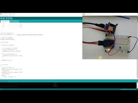
}For the examples I use this wire schema on breadboard: