babbleberry / rpi4-osdev Goto Github PK
View Code? Open in Web Editor NEWTutorial: Writing a "bare metal" operating system for Raspberry Pi 4
Home Page: https://www.rpi4os.com
License: Creative Commons Zero v1.0 Universal
Tutorial: Writing a "bare metal" operating system for Raspberry Pi 4
Home Page: https://www.rpi4os.com
License: Creative Commons Zero v1.0 Universal


For part 14, is there a reason you choose to use the ENC28J60 Ethernet LAN as compared with the built in ethernet or wifi? Are you theoretically able to do the same things usings the builtin parts of the raspberry pi?
The enum in io.c (part14-spi-ethernet) of pull up pull down register is the wrong way around.
Current implementation:
enum {
Pull_None = 0,
Pull_Down = 1, // Are down and up the right way around?
Pull_Up = 2
};
Correct implementation:
enum {
Pull_None = 0,
Pull_Down = 2,
Pull_Up = 1
};
source:

page 74 of bcm2711 ARM Peripherals
Hello!
I have been jumping into the world of OSDev and stumbled across your amazing write ups.
I am on step two creating the make file and I keep getting the error:
(.text.boot+0x34): undefined reference to 'main'
make: *** [Makefile:15: kernel18.img] Error 1
I am trying to figure out if the issue is in my linker.ld file or the Makefile itself. It seems to properly make the boot.o and kernel.o files but fails when trying to link them into one file.
I have checked multiple times my linker.ld file matches yours as well as the Makefile (minus the file path to the cross compiler).
Any suggestions of what I can try? Thanks for your help and for taking the time to make these tutorials!


Hi,
I am actually testing DMA with a wav file (unsigned 8bit, stereo, 44.1kHz). I saw this in config.txt (risc os):
ramfsfile=CMOS
ramfsaddr=0x508000
After some tests, I did this (address above 8F0 0000 will not work):
ramfsfile=audio.wav
ramfsaddr=0x1C0000
Because wav files (and header) are not so magic, I read the data like this (for DMA):
char * data = (char *) 0x1C0000;
unsigned size = *((unsigned *) (0x1C0000+40));
data += 44;
for (unsigned i=0; i<size; i++) *(safe+i) = *(data+i);
If someone wants to split sound and kernel, this would be a nice option ;-)
Links:
Minor point, which might be of use to others (possibly)...
I found that I had to change a line in the Makefile (on Catalina - may apply to others), setting the path for LLVMPATH:
#LLVMPATH = /opt/homebrew/opt/llvm/bin
LLVMPATH = /usr/local/opt/llvm/bin
I may also have had to run (but I'm not convinced that it was absolutely necessary):
export LDFLAGS="-L/usr/local/opt/llvm/lib -Wl,-rpath, /usr/local/opt/llvm/lib"
export CPPFLAGS="-I/usr/local/opt/llvm/include"
export LDFLAGS="-L/usr/local/opt/llvm/lib"
echo 'export PATH="/usr/local/opt/llvm/bin:$PATH"' >> ~/.zshrc
. ~/.zshrc
This last batch of commands was advised by the output of
brew install llvm
so I ran them just in case.
I was a bit confused about the PERIPHERAL_BASE being set to 0xFE000000 in these examples as the BCM2711 doc is listing a different base address in the docs. Then I stumbled over this sentence in the beginning of the docs:
So a peripheral described in this document as being at legacy address 0x7Enn_nnnn is available in the
35-bit address space at 0x4_7Enn_nnnn, and visible to the ARM at 0x0_FEnn_nnnn if Low Peripheral
mode is enabled.
So I'm assuming you are using this Low Peripheral mode? The docs say you need to specifically enable it though but do not seem to talk further about it. Where are you enabling this mode or is the wording confusing and its always enabled by default?
Also what is the use of it?
Nice tutorial, but please say a bit more about the bare minimum of files and config.txt
I need on my card this minimum for the UART example:
bxm2711-rpi-4-b.dtb (46.5 kB)config.txt (125 byte)kernel8.img (1.9 KB)start4.elf (2.2 MB) = GPU firmwareThe minimal content of config.txt:
[all]
core_freq_min=500
gpu_mem=128
A different gpu_mem like 64, 32 or 16 seams not to start the kernel (?)
Using WSL for emulating ubuntu, I downloaded and unpacked the latest x86_64 Linux hosted cross compilers (gcc-arm-10.3-2021.07-x86_64-aarch64-none-elf.tar.xz). After editing the makefile from part 2-building to point to my compiler directory, I got the following error:
/bin/rm kernel8.elf *.o *.img > /dev/null 2> /dev/null || true
../gcc-arm-10.3-2021.07-x86_64-aarch64-none-elf/bin/aarch64-none-elf-gcc -Wall -O2 -ffreestanding -nostdinc -nostdlib -nostartfiles -c boot.S -o boot.o
../gcc-arm-10.3-2021.07-x86_64-aarch64-none-elf/bin/aarch64-none-elf-gcc -Wall -O2 -ffreestanding -nostdinc -nostdlib -nostartfiles -c kernel.c -o kernel.o
../gcc-arm-10.3-2021.07-x86_64-aarch64-none-elf/bin/aarch64-none-elf-ld -nostdlib -nostartfiles boot.o kernel.o -T link.ld -o kernel8.elf
../gcc-arm-10.3-2021.07-x86_64-aarch64-none-elf/bin/aarch64-none-elf-ld: Error: unable to disambiguate: -nostartfiles (did you mean --nostartfiles ?)
make: *** [makefile:15: kernel8.img] Error 1
Changing -nostartfiles to --nostartfiles on the ld command resulted in unrecognized option '--nostartfiles'
Removing -nostartfiles resulted in a successful build, but I have not yet executed the image. Should this tag option be removed?
Thank you for your help and guidance!
A little note to this very well-done and useful tutorial series: in https://github.com/isometimes/rpi4-osdev/tree/master/part3-helloworld#connecting-the-cable you write:
The diagram below shows where you need to make connections. The BLACK connecter hooks over Ground (Pin 6), the WHITE over TXD (GPIO 14/Pin 8) and the GREEN over RXD (GPIO 15/Pin 10). As we are powering the RPi4 using a dedicated power supply, make sure you don't connect the RED connector.
For those of us that use a different Serial-to-USB cable, I think it would be useful to mention the connectors not (only) by color, by also by name, especially since according to what I read in other tutorials on connecting a Raspberry via UART, it's necessary to cross RXD and TXD, i.e. connect RXD to TXD and vice versa.
In part 8, The line towards the bottom, under Connecting to our Breakout controller from the Raspberry Pi, reads (the emphasis is mine to highlight the location):
gatttoolandhcitoolon Raspbian turned out to be very my good friends!
should be
gatttoolandhcitoolon Raspbian turned out to be my very good friends!
"my" and "very" are transposed.
Note that I am referring to the online tutorial on rps4os.com...
In part 3 it states:
Do you remember that, back in the first tutorial, I had to edit the config.txt file on the SD card to get Raspbian up on my TV screen? Now we need to add a line to ensure that our UART connection will be reliable.
However, the first mention of config.txt is actually in part 2 (not "back in the first tutorial") , and only in reference to running in 64 bit mode:
We’ll now copy our kernel8.img onto the SD card. This name is meaningful and it signals to the RPi4 that we want it to boot in 64-bit mode. We can also force this by setting
arm_64bitto a non-zero value in config.txt. Booting our OS into 64-bit mode will mean that we can take advantage of the larger memory capacity available to the RPi4.
So, where is the part about the TV screen? Is that missing from part 1? Or is it missing from part 2? The former seems most likely, although its being missing in part 2 would also make sense as that is where the screen is referred to (and expected to be black).
Please could you correct the online guide so that the edit to config.txt TV screen is shown and explained in which ever part each should be mentioned... and that the backreference to that (in part 3) is also accurate..?
Note that I haven't yet tried running any of the compiles or make files, nor made any code. I'm just reading and following your excellent (and interesting) guide - actually I've just started, and the above issue made me stop and scratch my head...
Many thanks.
Hi, I'm loving this tutorial! But I find myself wondering how I could have figured any of this out without a tutorial. Where did you get all this information? I mean things about the fundamental protocols you have to keep to to run code on the Pi 4. Like that the file has to be called kernel8.img, how the SD card has to be formatted, or like the actual format that the .img file should have (i.e. how to put the linker script together, the correct objcopy commands, etc).
Is this stuff even documented officially anywhere? All I can find are forum posts linking to more forum posts with shreds of information.
Hello! I've been following your tutorial, but when I copied the Makefile.gcc.windows, I renamed it just Makefile so I can type "make". But when I did that,, if gave me this error. I don't know if I'm using the wrong version of GCC or not. I made sure I had the ARM version.
del kernel8.elf *.o *.img /bin/sh: line 1: del: command not found make: *** [Makefile:22: clean] Error 127 PS E:\Repos\KemyonOS\KemyonOS\KemyonOS>
Are there any plans about MMU and physic & virtual memory management?
On part 14, you state:
Through a bit of trial & error I discovered that when GPIO08 is clear, the device is selected, and when it’s set, the device is deselected. If you can explain this to me, I’d love to hear from you - frankly, I was just pleased to get it working, so I moved on!
This is because the Chip Select pin on the ENC28J60 is active LOW, so the board, upon which the IC is placed ,just brings this pin out, without using an invertor (to save costs). You can see that the ENC28J60 is active LOW by looking at the datasheet of the ENC28J60: Note the /CS pin - the bar denotes active LOW. Hence GPIO08 must be LOW to enable the IC.
Hi, I’m not so sure if I’m doing this right and if my question is an issue at all, but just in case I’m leaving it here. I have read your code and I have enough knowledge to understand most part of it and actually get what is doing, but I would love to implement a kernel in cpp. Somehow I’m assuming at first that it will be connected to the compiler and compilation process, but I wouldn’t know how it should actually go.
In your excellent tutorials you mention you pursued BLE as USB was much more difficult. Could you sketch out the steps, as you see it, even if from a high level, on how to go about adding USB support to this Kernel?
I note you added the HCD file from the bluetooth firmware to your kernel. Is there a similar firmware we can leverage for the USB chip on these boards? Presumably this is a client server architecture (or host, client)?
Edit : I found this, is this any use? >> https://github.com/hathach/tinyusb
part 14's next link points to a 404ed https://www.rpi4os.com/part15-tcpip
the working url is https://www.rpi4os.com/part15-tcpip-webserver/
I wanted to build this project to test it on QEMU instead of having to switch back and forth between raspberry pi sd cards. I was wondering if you would give me a hand with it?
Hello,
I was having trouble getting UART1 to respond on my raspi 400, so I tried your code to check if I was missing something obvious; but there is still no output. :-(
Some things I checked:
/proc/iomem in raspbian to verify that the raspi 400 does list its UART at the same memory locations as the raspi 4.part5-framebuffer example to verify that the kernel does boot up and does execute the relevant instructions (the framebuffer output was visible).core_freq_min=500 and enable_uart=1 were included in the config.txtIt's possible that there is some other obscure difference between the raspi 4 and raspi 400, so I am considering splashing out on a raspi 4B to test with....
I wonder if you have any ideas?
Thanks for the write up!
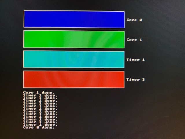
I tried out part 13, which worked as expected, other than the "Timer 3" bar never filled on my Raspberry Pi 400.

Perhaps this is ok, but since it differs from your screenshot I thought I'd let you know. Feel free to close if this isn't an issue.
This is using latest raspberry pi firmware (commit 93d3f791a28ab369a62d2baf06035fc533b00864) and my config.txt looks like:
core_freq_min=500
disable_commandline_tags=1
kernel_old=1
arm_64bit=1
hdmi_group=1
hdmi_mode=16
Hi,
Thanks for putting together this tutorial. I have a RPi 1 from 2012 with 512 MB RAM and wanted to follow your tutorial on it. Just wondering if it might work?
Hi,
Are you interested in writing a demo showing the pictures captured by the camera module.
That way it's easy to find the page from Github
Hi! first of all, thank you for writing this guide.
I followed everything in part 2-building and wrote my own kernel.c due to I have no UART connector.
// kernel.c
#define BCM2711_PERI_BASE_ADDR 0xFE000000
#define GPIO_BASE_ADDR BCM2711_PERI_BASE_ADDR + 0x200000

#define OUT_PIN 21

volatile unsigned *m_pGPIO;

void setGPIOModeInput(int pin)
{
    const int reg = pin / 10;
    const int shift = (pin % 10) * 3;
    *(m_pGPIO + reg) = ((*(m_pGPIO + reg) & ~(7 << shift)) | (0 << shift));
}

void setGPIOModeOutput(int pin)
{
    setGPIOModeInput(pin);
    const int reg = pin / 10;
    const int shift = (pin % 10) * 3;
    *(m_pGPIO + reg) = ((*(m_pGPIO + reg) & ~(7 << shift)) | (1 << shift));
}

inline __attribute__((always_inline)) void setGPIO(int pin)
{
    *(m_pGPIO + 7) = 1 << pin;
}
inline __attribute__((always_inline)) void clrGPIO(int pin)
{
    *(m_pGPIO + 10) = 1 << pin;
}

int main(void)
{
    m_pGPIO = (volatile unsigned *)GPIO_BASE_ADDR;

    setGPIOModeOutput(OUT_PIN);

    while (1)
    {
        setGPIO(OUT_PIN);
        clrGPIO(OUT_PIN);
    }
}
And I made the latest Raspbian-Lite (64bit) micro SD card using raspberry pi imager. Then replaced the kernel8.img.
I expected GPIO21 (40 for hardware) to generate spikes, but it didn't.
I'm not even sure whether the boot sequence is done; I found this post on the forum. They say the kernel load address is changed to 0x200000.
Is this guide affected by that post? If not, I'll assume that the kernel.c contains problems.
A minor point but the SI unit for frequency is Hz not hz. Also, there should be a [non-breaking] space ( ) before SI units (see Don't forget the space!).
So
The Raspberry Pi 4’s clock oscillator frequency is 54Mhz
should be
The Raspberry Pi 4’s clock oscillator frequency is 54 MHz
The Raspberry Pi 4’s clock oscillator frequency is 54 MHz
and
Technically speaking, it’s 8-bit, unsigned PCM data at 44.1Khz
should be
Technically speaking, it’s 8-bit, unsigned PCM data at 44.1 KHz
Technically speaking, it’s 8-bit, unsigned PCM data at 44.1 KHz
There are also four other instances in this paragraph:
These pulses/bursts do need to be highly accurate for this trick to work, and so we need a reliable clock source. Just like your kitchen clock ticks every second, so the oscillator on the Raspberry Pi 4 has a regular ‘tick’ - in this case, 54,000,000 times per second (54Mhz)! Our audio sample is at 44.1Khz though, so we need to ‘slow it down’. We do this by first stopping the clock, then setting a clock divisor, setting the PWM range, and enabling the clock again. In my code, I use 2 as the clock divisor (so we’re down to 27Mhz) and set the range to 612 (0x264). Essentially, this means that our PWM module will move to a new sample every 27,000,000/612 times per second - roughly equivalent to 44.1Khz, which just happens to be the sample rate of the included audio sample
audio.bin(I’ve includedaudio.wavso you can listen normally on your laptop too!).
Hi,
I've stumbled across an issue when building upon the 3rd part.
Immediately after the kernel is loaded in the higher half (at 0xffffffff80000000), I enable UART with mmio_write(UART_ENABLE, 1);.
However, instead of completing the UART initialization function and outputting "Hello World", I get a Synchronous Exception at the address of mmio_write().
To better fit my coding style, I replaced the integer types as follows:
void mmio_write(uint32_t reg, uint8_t val)
{
	*(volatile uint8_t *)reg = val;
}
I'm using the Limine bootloader to boot my kernel with the UEFI firmware easily.
Do you have any idea what could be wrong?
Here's the linker file I use.
In part5-framebuffer/fb.c line 15, you have given the value buffer size in bytes a second time for mbox[4].
Based on my understanding of https://github.com/raspberrypi/firmware/wiki/Mailbox-property-interface, this should actually be set to 0 for the "request code"; I think that this is coincidentally working right now because the only requirement is for bit 31 to be clear (which is the case for your sizes).
After the tag response has been written by the GPU, this value should have been changed to 0x80000000 (i.e. bit 31 set). These request/response values are the same as the buffer request/response code (which you correctly set on line 11 to mbox[1]), which can be a bit confusing.
In part 5, you implement the mailbox protocol which is "documented" here. Your function mbox_call() is basically a C implementation of the algorithm described in that document:
- Read the status register until the empty flag is not set
- Read data from the read register
- If the lower four bits do not match the channel number desired then repeat from 1
- The upper 28 bits are the returned data
The relevant part of your code is:
while (1) {
    while (mmio_read(MBOX_STATUS) & MBOX_EMPTY);
    if (r == mmio_read(MBOX_READ))
        return mbox[1]==MBOX_RESPONSE;
}
However, you can see that that if statement does not quite match step (3). Instead of just checking if the channel number matches the value of the read register, we check if the whole thing matches our entire message (28 bits of address + 4 bits of channel).
What justifies this?
During the learning process, I found that the code would get stuck in a specific position in the initBricks function. I found the location of the error, but I cannot understand the cause of the error.
objects[numobjs].width = brickwidth;
//The error is here
objects[numobjs].height = brickheight;
The code will get stuck here. But as long as you add other meaningful code between these two lines, it will run normally. For example, "wait_msec(1)" or other commands.
Can you help answer this question? :D
Hi,
Thanks for this amazing tutorial! It would be great if you had mentioned that partially based on my tutorials for the RPi3 (I can recognize my own code :-)).
https://github.com/bztsrc/raspi3-tutorial
There's nothing wrong with using that code, it is licensed under MIT. But if you could put attribution in your readme.md, then in return I would recommend this tutorial in my readme.md too!
Cheers,
bzt
I'm following this (pretty amazing) tutorial on my rpi itself, rather than a windows or ubuntu pc. However, the building part is an issue. I've downloaded the "AArch64 ELF bare-metal target" for aarch64 but it doesn't work. Any idea on why?
Thanks in advance!
output:
/bin/rm kernel8.elf *.o *.img > /dev/null 2> /dev/null || true
gcc-arm-compiler/bin/aarch64-none-elf-gcc -Wall -O2 -ffreestanding -nostdinc -nostdlib -nostartfiles -c boot.S -o boot.o
gcc-arm-compiler/bin/aarch64-none-elf-gcc: 1: gcc-arm-compiler/bin/aarch64-none-elf-gcc: ELF�������0d@@���@8: not found
gcc-arm-compiler/bin/aarch64-none-elf-gcc: 7: gcc-arm-compiler/bin/aarch64-none-elf-gcc: Syntax error: "(" unexpected
make: *** [Makefile:9: boot.o] Error 2
PS: I've extracted the .tar.xz file in my project folder and renamed the directory to 'gcc-arm-compiler'. I've also made these changes in the makefile, where i replaced the GCCPATH
On the page for part 11, the link to the video isn't hypertext. You have to right click and select "Go to..."
On the github page it appears as an embedded video, however on the rpi4os website it does not:

I notice when i draw images that are quite large, take a long time in drawing all pixels.
Is there a way to improve this? I looked up into dual buffering technique but still not sure how to do that.
Otherwise what would allow best to draw images without lag or a sliding scanner?
A declarative, efficient, and flexible JavaScript library for building user interfaces.
🖖 Vue.js is a progressive, incrementally-adoptable JavaScript framework for building UI on the web.
TypeScript is a superset of JavaScript that compiles to clean JavaScript output.
An Open Source Machine Learning Framework for Everyone
The Web framework for perfectionists with deadlines.
A PHP framework for web artisans
Bring data to life with SVG, Canvas and HTML. 📊📈🎉
JavaScript (JS) is a lightweight interpreted programming language with first-class functions.
Some thing interesting about web. New door for the world.
A server is a program made to process requests and deliver data to clients.
Machine learning is a way of modeling and interpreting data that allows a piece of software to respond intelligently.
Some thing interesting about visualization, use data art
Some thing interesting about game, make everyone happy.
We are working to build community through open source technology. NB: members must have two-factor auth.
Open source projects and samples from Microsoft.
Google ❤️ Open Source for everyone.
Alibaba Open Source for everyone
Data-Driven Documents codes.
China tencent open source team.