Arduino thrust tester
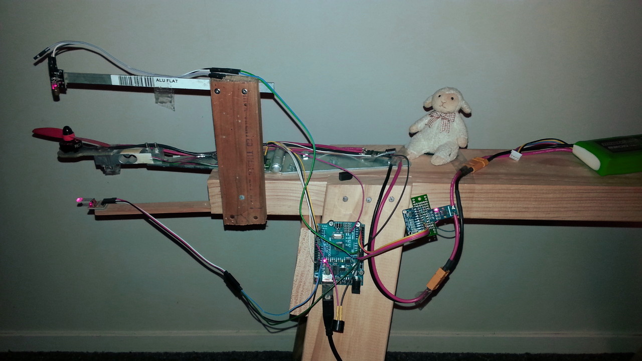
This project allows an Arduino to interface with a desktop computer to control the speed of a motor and read in values from various sensors to measure thrust, voltage, current, and rpm. The intended usage is to test the thrust performance and efficiency of motor/speed-controller/propeller combinations used in radio-control aircraft, although it might perhaps be useful for other purposes.
Control of the motor can be scripted to produce repeatable tests by giving specific input values to the motor controller. Using feedback from the sensors, the motor can be made to adjust its speed to meet a desired sensor reading (eg. thrust, rpm). The software to make this happen consists of an Arduino 'sketch' and a Qt based C++ application, which communicate with each other over a USB/serial (UART) connection.
Requirements
You will need a 5v/16MHz Arduino (I tested with Arduino Unos), a Linux or Windows computer, and of course a motor+ESC+propeller as the subject of the test. At least one sensor is needed to do any meaningful testing, typically this would be a load cell (with amp) to measure the thrust. To measure voltage I used an analog-to-digital converter module, for current a hall sensor and the same ADC module, and to measure rpm I used a cheap laser emitter/receiver module pair. You can add a 5v continuous buzzer to provide sound queues.
If you are willing to modify the parts of the Arduino sketch that read the sensors, you could instead use other kinds of sensors fairly easily (but increasing the total number of sensors above four will involve considerable work on both the Arduino sketch and the desktop program).
The sensors and connection pins that the sketch is written for are outlined below. You can find an explanation of this setup on YouTube: https://youtu.be/PfVJmci9IQQ
The main graph view of the desktop app uses OpenGL, so your computer should have some decent graphics hardware to display this.
Components and connections
Arduino
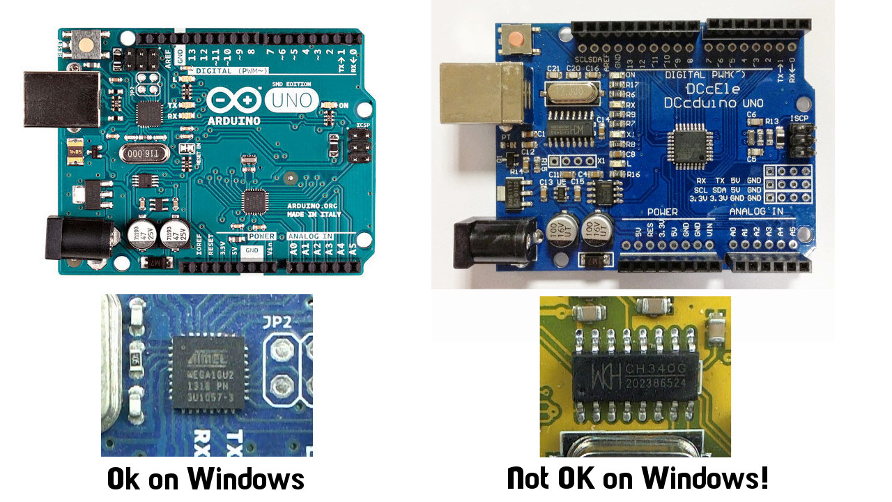
I tried this with Arduino Unos. On Linux I had no problems with a 'clone' Arduino using a CH341 USB-to-serial chip, but the same Arduino had big problems on Windows. It seems that the Windows driver for the CH340/CH341 does not play nicely with the libserialport library used by the desktop app. So if you're using Windows, make sure your Arduino has an atmega16u2 instead of a CH340 or CH341 USB-to-serial adapter.
There are a lot of connections to make, so it really helps if you can find one of those Unos that have double rows of pins (one male, one female) on each side. The clone Arduino I use on Linux is great because it has the double rows of pins and also a few extra GND pins here and there, plus extra breakouts for 3.3v, I2C and UART (Banggood: https://goo.gl/Y7G7td).
Motor speed controller
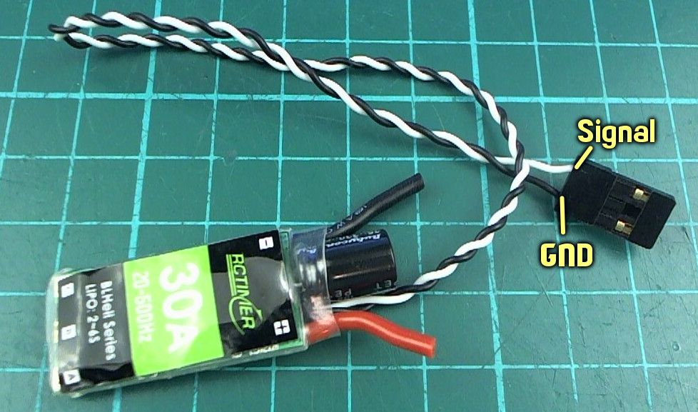
The ESC should be using regular PWM (not Oneshot125 etc) and be calibrated to the range 1000μs for zero throttle and 2000μs for full throttle. You can use the desktop app to calibrate the ESC (set the throttle to full before powering up the ESC, then to zero after powering it up).
ESC <----> Arduino
- GND <----> GND
- Signal <----> Pin 5
Load cell amplifier
Example load cell (Banggood): https://goo.gl/roJTGl
The load cell amplifier is a HX711, these are cheap and easy to find (Banggood: https://goo.gl/fIdfvA). I think you can use either 5v or 3.3v for the VCC, I used 3.3v simply because the 5v pins of the Arduino were in use.
The connections between the load cell and the amp will depend on the type of load cell you get. General info: https://learn.sparkfun.com/tutorials/load-cell-amplifier-hx711-breakout-hookup-guide
HX711 <----> Arduino
- GND <----> GND
- VCC <----> 3.3v
- DT <----> Pin 3
- SCK <----> Pin 4
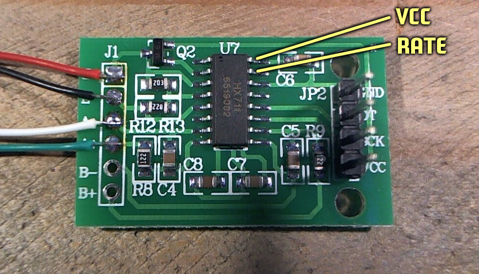
The HX711 can run at either 10Hz or 80Hz update rate. Obviously we want the faster rate, but most HX711 module boards come configured as 10Hz. To change it to 80Hz you will need to disconnect the RATE pin 15 from the pad it is soldered to, and connect it to VCC (easiest way is to use pin 16 which is right next to it).
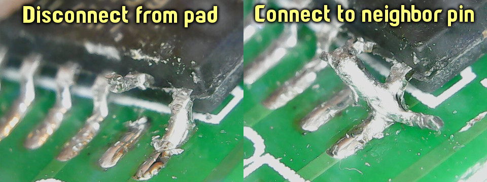
Do not be a lazy ass and simply connect it to the neighbor without disconnecting it from the pad first - that will cause VCC and GND to be shorted together!
Analog-to-digital converter
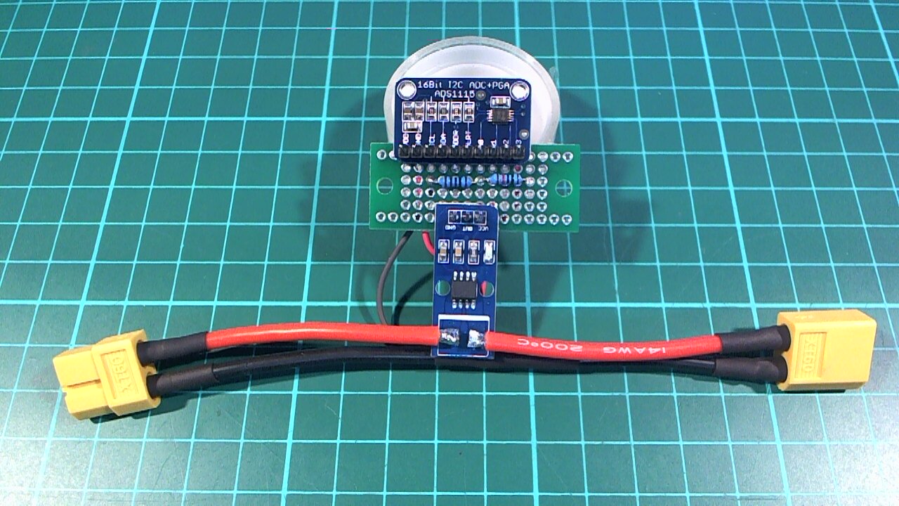
The ADC is a ADS1115 which provides two 16-bit relative converters and communicates with the Arduino via I2C (Banggood: https://goo.gl/OO30Ym).
You can use one converter to measure voltage (with an appropriate voltage divider) and the other to measure the output of the Hall sensor (current reading).
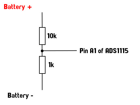
The voltage divider will depend on the maximum voltage of the battery you intend to test with, and MUST ensure that the maximum voltage is under 5v. I used a 10:1 divider (10k and 1k resistors) which means in theory I can test a battery of up to 50v. In practice you might want to avoid pushing that limit. In any case I do not intend to use higher than a 4 cell lipo (16.8v at full charge) so this should be fine.
Note that you can also use the analog pins of the arduino directly to measure voltage, but the resolution is only 10 bit (0-1023) which is not so good. For example a 3S lipo going from full charge (12.6v) to low charge (say 10.6v) is 2v change, so a 10:1 voltage divider sees 0.2v change, or 0.2/5 of the 0-1023 range which is only about 40 discrete steps, ie. a resolution of about 0.05v per step. Acceptable I suppose, but the situation is worse for the current sensor which deals in smaller ranges. If you only want to measure voltage, using a simple analogRead would probably be fine, but if you want to measure current and you have a ADS1115 you might as well also use it to measure the voltage, so the 16-bit ADC will give a voltage resolution of around 0.0008v.
General info: http://henrysbench.capnfatz.com/henrys-bench/arduino-voltage-measurements/arduino-ads1115-module-getting-started-tutorial
ADS1115 <----> Arduino
- GND <----> GND
- VDD <----> 5v
- SDA <----> Pin A4
- SCL <----> Pin A5
- A0 <----> GND
- A1 <----> Middle of 10:1 voltage divider (I used 10k and 1k, smaller resistor goes on ground side)
- A2 <----> GND
- A3 <----> OUT pin of ACS712
Hall (current) sensor
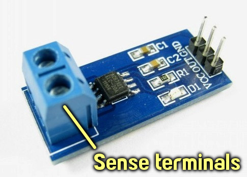
The Hall sensor is a ACS712 (Banggood: https://goo.gl/hqIrqE)
This particular sensor is rated to 30A maximum, some miniquad motors are now topping out at around this level so you might want to try a higher-spec one depending on what kind of loads you're testing. The OUT pin of this sensor will give an analog voltage (0-5v) corresponding to the current flowing through the sense terminals. This analog voltage is given to the ADC to get a digital value. You could use regular analogRead of the Arduino instead, but most likely the voltage range will be too small to get good readings.
General info: http://embedded-lab.com/blog/a-brief-overview-of-allegro-acs712-current-sensor-part-1
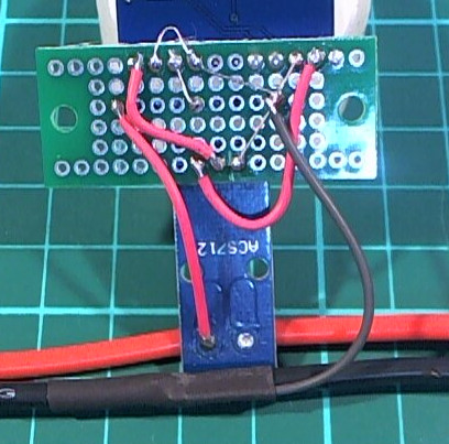
ACS712 <----> Arduino
- GND <----> GND
- VCC <----> 5v
- OUT <----> A3 of ADS1115
- Sense terminals should bridge a break in the main power line
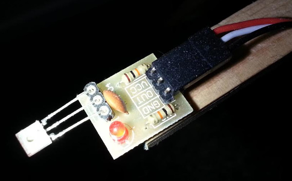
Laser TX
This will simply stay on all the time the Arduino is powered, there is no need to control it in any way. I have left the laser on for most of the day on many occasions and it does not seem to get hot or anything. Better to arrange this pointing downward rather than upward so that you don't inadvertently look into it when leaning over the thrust tester.
TX <----> Arduino
- GND <----> GND
- VCC (S) <----> 5v
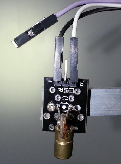
Laser RX
RX <----> Arduino
- GND <----> GND
- VCC <----> 5v
- OUT <----> Pin 2
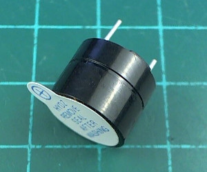
Buzzer
Make sure you get a buzzer that is a 'continuous' one, that is, powering it with 5v is all that is necessary to make it sound (some buzzers require the input voltage to be pulsed on and off to make a sound).
Example (Banggood) https://goo.gl/Y11zJG
Buzzer <----> Arduino
- GND <----> GND
- VCC (+) <----> Pin 7
Safety concerns
Keep in mind that there is potential for injury here. There is currently no concept of 'arming' or a disarmed state so the motor will spin any time the battery is connected and the slider in the desktop app is moved, or when the scripted test is executed. By the nature of this kind of testing the motor will sometimes be taken to the full-throttle limit, and these motors have tons of power. Even a little 1804 on 3S is quite scary to have nearby at full blast. I have not seen any issues with spurious control inputs or any sudden unwanted motor startups, but please regard your test stand with a healthy degree of suspicion when the battery is connected. Ideally, only connect the battery when you're about to run a test, add a buzzer to your setup, and have a 'beep' and 'wait' step in your script as an audible warning before continuing with the test.
Make sure your test stand is solidly constructed and cannot wobble around or tip over when the motor is unleashed. You might want to also have a screen of some kind between you and the motor just in case a prop breaks and the blade flies out. I take no responsibility for any accidents that might occur!
Basic usage
After making the connections as above for whatever sensors you'll be using, upload the sketch to your Arduino.
Run the desktop app and you should see your Arduino listed in the pull-down list in the upper left. If you disconnect or reconnect it, you can click on 'Update list' to refresh the list.
Clicking 'Open' should connect to the Arduino and start displaying samples from the sensors. If you have a buzzer connected you'll hear two quick beeps when connecting.
If you do not see the graph values scrolling in, the connection either failed or there is a problem with the connection. On Windows if you see the graph values scrolling in but they sometimes pause or stutter, you might be having the driver issue that I had with my CH341 Arduino (see above). Any sensors that are not present will report garbage values that can be ignored.
At this point you should be ready to start. Some points to note:
- with a battery connected to the ESC, you should be able to move the slider to control the motor speed
- hitting the Escape key at any time will set the throttle value to zero and abort any test that was running
- disconnecting or closing the app while the motor is running should also set the throttle value to zero
For more details about how the app works, please see this YouTube video: https://youtu.be/PfVJmci9IQQ
Sensor calibration
Click the 'Calibrate sensors' button to bring up the sensor calibration dialog. Calibration consists of taking a measurement of a zero value (eg. zero thrust, zero voltage, zero current) and a known non-zero value. To measure a known non-zero value for thrust you will need something to hang from the motor/prop that you know the weight of. To measure a non-zero voltage/current you will need a multi-meter.
Thrust: With the prop on the motor (battery disconnected!) click 'Measure zero'. Hang your known weight from the motor shaft, enter the weight in the text input and click 'Measure known weight'.
Voltage: With the battery disconnected click 'Measure zero'. With the battery connected, measure the battery voltage with your multi-meter, enter it in the text input and click 'Measure voltage'.
Current: With the battery disconnected click 'Measure zero'. Connect your multi-meter in series with the battery. With the battery connected, use the slider in the main window to set the motor to a medium speed. Enter the current as shown on your multi-meter into the text input and click 'Measure voltage'.
Test definition
Clicking the 'Define test' button will bring up a dialog where you can define a sequence of inputs to give to the motor controller. This is done by entering some text in the left hand side of the dialog. Each line of text represents one 'test' and is of the format type , duration, parameter where the meaning of 'parameter' will depend on the type of test. Test types are wait (w), beep (b), constant throttle/speed (s), constant thrust (t), constant rpm (r).
Examples:
- w, 2 = wait for two seconds
- b, 1 = beep for one second
- s, 5, 1200 = set the throttle value to 1200μs for five seconds
- t, 5, 150 = adjust the throttle to produce 150g of thrust for five seconds
- r, 5, 3000 = adjust the throttle to produce 3000rpm for five seconds
Any lines not recognized as one of these formats will be ignored. Lines that are recognized will be listed on the right hand side of the dialog.
Warning: Do not use values for the constant thrust or constant rpm tests that you have not already seen to be viable, either manually by using the slider, or by running a constant throttle test. For example if your motor setup gives you 350g thrust and 9500rpm at full throttle, you cannot expect the automatically adjusting tests to achieve anything higher than that. Ideally you should set your target values for thrust or rpm to be considerably less than this, because the battery will sag as the test progresses.
Online test results
The desktop app interfaces with iforce2d.net to fetch lists of parts, and to upload your test results for others to see. Work on this will probably not be continued, fwiw you can find it here:
http://www.iforce2d.net/tts/parts.html
http://www.iforce2d.net/tts/reports.html
For more details about this, please see this YouTube video: https://youtu.be/PfVJmci9IQQ
Binaries
You can find builds of the desktop app for Linux and Windows in the 'bin' folder. Don't ask me for a Mac build.
Building the desktop app
On Linux you will need to first build and install the libserialport library. This is part of the sigrok project, you can find the source and instructions here: https://sigrok.org/wiki/Libserialport
The desktop app has been checked with Qt 4.8 on Linux and Qt 5.7 on Windows. The .pro file should open and build with QtCreator without issue (mingw32 on Windows).
Actually 'should' is a little too confident... let's say it 'might' build without issue.
On OSX you need to install qt4 and libserialport using brew. see http://brew.sh/
$ brew install qt4 $ brew install --HEAD rene-dev/sigrok/libserialport $ qmake tts.pro $ make $ open tts.app


