Giter VIP home page Giter VIP logo

gridspace / grid-apps Goto Github PK

View Code? Open in Web Editor NEW
402.0 31.0 134.0 9.74 MB

Browser-based Slicer for 3D Printing, CAM, Laser (Kiri:Moto) and mesh editor (Mesh:Tool)

Home Page: https://grid.space/

License: MIT License

JavaScript 87.72% Roff 2.58% HTML 2.41% CSS 1.91% Prolog 0.03% CWeb 0.04% G-code 0.01% Assembly 0.01% C 0.20% Makefile 0.01% C++ 5.02% Macaulay2 0.05% Dockerfile 0.01% Shell 0.01%

grid-apps's Introduction

Grid.Space Web Applications

Website GitHub package.json version (branch) GitHub package.json version (branch) GitHub package.json version (branch) GitHub package.json version (branch)

Grid.Space hosts several live versions of this code

Kiri:Moto is a browser-based Slicer for 3D printers, CNC mills, and Laser cutters

Mesh:Tool is a browser-based mesh repair and editing tool

Primary Documentation

https://docs.grid.space/projects/kiri-moto

https://docs.grid.space/projects/mesh-tool

Development Activity

GitHub commit activity GitHub last commit GitHub contributors

Community Engagement

Discord | YouTube | Twitter

Discord GitHub Donate Twitter Follow

Testing Locally (with Docker)

git clone [email protected]:GridSpace/grid-apps.git
cd grid-apps
docker-compose -f src/dock/compose.yml up

Testing Locally (with NodeJS)

git clone [email protected]:GridSpace/grid-apps.git
cd grid-apps
npm i
npm install -g @gridspace/app-server
gs-app-server --debug

to start a local instance of the apps. then use a browser to open localhost:8080/kiri

if installing the app-server fails or gives you permissions errors, then your node installation (on linux/mac) is installed as another user (like root). try instead:

sudo npm install -g @gridspace/app-server

Alternatively, if you are using a packaged version of npm that ships with a Linux distribution, but still want to install in your home directory, you can use

npm config set prefix ~/.local

If gs-app-server is not found, then perhaps ~/.local/bin is not in your path. You can either add it to your path, or you can run:

~/.local/bin/gs-app-server --debug

You can now access your environment of grid-apps by going to localhost:8080/kiri

Windows Developers

this git repo requires symbolic link support. on Windows, this means you have to clone the repo in a command shell with Administrator privileges.

Other Start Options

gs-app-server

serves code as obfuscated, compressed bundles. this is the mode used to run on a public web site.

requires node.js 12+

Javascript Slicing APIs

A script include that injects a web worker into the page that will asynchronously perform any of Kiri’s slicing and gcode generation functions. And a frame messaging API for controlling Kiri:Moto inside an IFrame.

grid-apps's People

Contributors

albertmn avatar bgrumbine avatar conoria avatar daadu avatar dopp-io avatar doppitar avatar filipgoc avatar gompa avatar johnsonm avatar jsiddall avatar juodumas avatar lgeek avatar ludwich66 avatar mathiaslec avatar oliof avatar p3d-dev avatar pastitas avatar probonopd avatar salyarka avatar smartin015 avatar ssilverm avatar stewartoallen avatar tibus avatar tovrstra avatar type8 avatar

Stargazers

 avatar  avatar  avatar  avatar  avatar  avatar  avatar  avatar  avatar  avatar  avatar  avatar  avatar  avatar  avatar  avatar  avatar  avatar  avatar  avatar  avatar  avatar  avatar  avatar  avatar  avatar  avatar  avatar  avatar  avatar  avatar  avatar  avatar  avatar  avatar  avatar  avatar  avatar  avatar  avatar  avatar  avatar  avatar  avatar  avatar  avatar  avatar  avatar  avatar  avatar  avatar  avatar  avatar  avatar  avatar  avatar  avatar  avatar  avatar  avatar  avatar  avatar  avatar  avatar  avatar  avatar  avatar  avatar  avatar  avatar  avatar  avatar  avatar  avatar  avatar  avatar  avatar  avatar  avatar  avatar  avatar  avatar  avatar  avatar  avatar  avatar  avatar  avatar  avatar  avatar  avatar  avatar  avatar  avatar  avatar  avatar  avatar  avatar  avatar  avatar

Watchers

 avatar  avatar  avatar  avatar  avatar  avatar  avatar  avatar  avatar  avatar  avatar  avatar  avatar  avatar  avatar  avatar  avatar  avatar  avatar  avatar  avatar  avatar  avatar  avatar  avatar  avatar  avatar  avatar  avatar  avatar  avatar

grid-apps's Issues

Which license is valid?

js/license.js says LICENSE:"Unauthorized copying, modification and re-distribution are strictly prohibited without prior written consent.",

but

license.md is MIT.

Allow to locate g-code origin (zero) to any place of model

It's not possible to set g-code origin to selected feature of model. For example if i want to place the zero to the highlighted point:

image

This is useful as hell when milling new features on preexisting part (eg. "pocket only" operation). It's not always practical to use part corner or center as origin. This is very different from 3d printing, where you just need to hit somewhere on the heatbed and doesn't really matter if you are perfectly centered.

Let's break it down:

  • First useful step would be to indicate where the g-code zero point will be in arrange and preview modes. Origin point is alpha and omega of g-code, please display it.
  • Real killer feature would be to allow use coordinate origin of the STL model. Just simple checkbox ["preserve model origin"] that would take zero from STL file without moving it to corner or center like kiri does right now. This feature alone would allow me to set zero in CAD and don't have to move it in kiri:moto. This is how i usualy handle my origin in 2D CAD/CAM process. I already know where the origin is when i am making the drawing, so all i want from CAM is to leave it as it is. Only problematic part about this is how you will handle multiple imports or clones. You can use first imported origin, let user select one of the models to take origin from or even disable this feature completely in that case. (it's probably not that useful when milling multiple STL files at once...)
  • Next step would be to allow to move it to any corner or edge of bounding box
  • Then it would help to allow origin to be moved to any place by manualy entering/jogging the coordinate numbers (while having live preview). This is useful in cases when you want origin to lay far outside of the model.
  • Final step would be to allow moving origin by simply clicking on model feature. STLs are made of triangles, so it might make sense to show wireframe of these triangles and set the g-code origin by clicking on corner vertex of one of these triangles.

Right-hand side settings in printer profiles

Would it be possible to pre-configure the right-hand side settings in printer profiles? I think some of the right-hand side defaults are not ideal for my printer, and hence would like to provide a more suitable set of settings as part of the printer profile.

Spiral path for finishing and roughing

Spiral path could be another usefull finishing operation in adition to waterline and linear. It might add another level of smoothness when finishing some objects.

Also it might be usefull in roughing and cuting out the part. Especially in harder materials, since endmills tend to plunge very slowly. It's easier on both tool and machine if you plunge slowly during whole round instead of cuting around and plunge directly. Endmills plunge easier when also moving to side. I am having troubles plunging into acrylic and aluminum with my DIY CNC. Spiral cuting solves that.
It also SAVES TIME! since there's no need to wait for plunging (which is typicaly slower than feedrate) to complete between layers, since plunging was already done during feed, so we can continue with another layer immediately.

Do you think it will be possible to add?

Examples finishing

image
image
image
image

Examples roughing:

image

Getting "no processes selected" error when attempting to slice

Hi.

Trying to use kiri moto for the first time, but when I press the slice button, I get a popup error message saying "no processes selected".
This happens with the default cube, as well as with my own stl file
image

I've tried this on both Safari 11.1.2 & Chrome 68.0.3440.106.

My steps:

  • open kiri moto page
  • select mode as "cnc milling"
  • setup devices picking the xcarve 1000
  • click 'slice' (i.e. leave everything else as defaults)

Any suggestions for what I'm doing wrong?

Thanks!

Laser Cutting slice step fails in OnShape

When slicing a part in OnShape using kiri:moto, instead of being successful as usual I consistently get an alert box which says "true".

I'm using a Chromebook Pixel 2 (always the up to date version of Chrome).

I think this is in part due to c1fdd34 (where I've made a similar comment).

WinCNC doesn't like M3 Sxxx on the same line

I've adapted Kiri:Moto's g-code output as much as possible, but it seems to always send (for instance):

M3 S18000

Which WinCNC finds unacceptable, griping about 'multiple commands'. Any way to get Kiri:Moto to put them on separate lines instead?

Support for V-bits, rounded bits and non-centercutting bits

image

V-bits are quite common and usefull, because they are quite durable and can both remove material in bulk and carve tiny details (up to 0.1 mm). These would be most usefull to add.

Rounded bits are similar to ball ends, but radius of the end is smaller than radius of the shaft. They are like hybrid between ball head and plain old square end mill. I kinda like them, because they produce smoother pocket bottoms. Also they are less prone to break, since they don't have sharp corners that make weak spot of most endmills and create leverage that puts whole tool under bigger load.

Non-centercutting bits would be harder to add, since they can't plunge too much and therefore require spiral cutting (#17). These are usualy cheap bits made for fast cutting/routing.

Update the model when it has been edited

The model in Kiri:Moto inside Onshape seems to be always stuck to the version in time at which it was update into Kiri:Moto. If you are not careful, you may end up printing an outdated model. Would it be possible to automatically refresh the sliced model when it has been edited in the Part Studio, or at least have a dialog box inform the user that it is no longer recent?

Mill and finish the pockets first, cut out later

It would make sense to mill and finish the pockets first and cut out the part from stock later. That way you have enough support for milling. Most of the time you can even make it without using cutout tabs if going in this order.

Tool change turns off spindle

On our old LinuxCNC Fireball, when it processes the M6 T1 tool change command, the spindle stops. We need to either remove the M6 T1 or add a M3 Snnnn after the M6 to get back up to speed. It seems like adding the M3 Snnnn would be correct.

Can't drill holes that are just slightly bigger than tool diameter

I am using 1/8'' (3.175mm) endmill tool. I've made this model (image) with holes of following diameters:
3 mm, 3.175 mm, 3.2 mm and 4 mm. Only the 4mm one is milled by roughing and waterline processes.

I expected that 3.175 or at least 3.2mm and bigger holes will be drilled. But nothing happend.
I also tried to enable "drilling" process, but it didn't changed anything. I've tried to look it up in documentation and even source code, but i still can't figure how to make use of this drilling feature.

image

Locks up on Preview with no processes

I imported my object then selected it and hit 'preview' ( in 'CNC Milling' mode if it matters ) and then hit an infinitely-repeating "there are no processes" popup. I had to force-reload the page to break it.

Some features on recognized if the end mill and the cut width is the same.

I was trying to cut a 2mm channel in a part with a 2mm end mill, and I found that curved features (like a circular channel) are not generating gcode to cut those features out. I suspect that since the model is represented by polygons, there are areas between the two walls which are less than 2mm, which means that the software will not recognize those areas as being able to be cut out.

Changing the tool diameter to 1.99mm seems to solve this issue, and it probably has an insignificant effect on the part tolerance, but I wanted to bring it up just in case there's a way to fix the issue.

Thanks!

I have uploaded the part I used to test out this issue.

Test part.zip

First Rapid Move from z=0

Inventables: NeilFerreri15h to StewartAllen

@stewartallen I just came back to check out your tool. I am still seeing an issue when the stock size is set. The first rapid move should be at a safe height, but it appears that with any stock that is greater than the height of the part it will do a rapid move to the safe height as if the part was at the bottom of the stock. For example, let's say I had a part that was 10mm in Z height, a safe height of 1mm, and my stock set at 50mm height. I'd want my first move to go to whatever XY at a height of 1mm. I am seeing that the first move would be G0 Xwhatever Ywhatever Z-39 Then it goes on to plunge UP to Z-2 or whatever.
Does that make sense?

Specify custom mills in Kiri:Moto

Hello,
it would be nice if i could add new tools in Kiri:Moto. Endmills with custom diameter should be easy to do.
Mills of different shapes might be harder to implement (ball nose, rounded, V-bit, etc...)

Add orthographic projection

Hello,
would it be possible to add little checkbox to enable orthographic projection?
It's quite usefull for quick shape inspection.

App loading fails / Variable t declared twice

Using OSX / Safari 10.1.1
Javascript fails / Page almost blank
Error seen in console:

[Error] SyntaxError: Cannot declare a let variable twice: 't'.
(fonction anonyme) (1.2.6e:3)

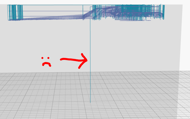
which points here (line 1937)
Kt.Clipper.prototype.ProcessEdgesAtTopOfScanbeam = function(t) {

Laser Cutter line colors

I've got access to a ULS laser cutter/engraver at the local tech school. The way they have it set-up it expects red lines for vector cuts, blue lines for vector engraving, and any other color (or wide lines) is done with raster engraving.

It seems that Kiri:Moto SVG output has blue lines hard coded, but it looks fairly simple to change this in a local repository, but I don't understand how I would go about testing it from OnShape. Any guidance?

Linear X/Y finishing does not travel all the way thru outline of irregular objects leaving poor surface

This can be easily seen on this OpenSCAD part that linear finishing operation does not cover whole part properly:

$fn=150;

union() {
sphere(10);
translate([0,0,-5]) cylinder(10,10,10, true);
}

image

image

Here's g-code interpretted by simulator:

image

Settings:

image

It actually affects real parts. I've been milling some prototype part from recycled plastic which is quite bad material, however it was still outstanding even on such bad surface and is still visible even after i sanded it down quite a bit. You can see the premature end of surface finish where i made the red lines:

image

Same code as simulated:

$fn=200;

translate([0,0,-15]) intersection() {
    difference() {
        cylinder(15,12.5,12.5);
        translate([0,0,-2]) cylinder(20,5,5);
    }
    translate([0,20,1]) rotate([90,0,0]) cylinder(40,14,14);
}

image

(Cou can also see destroyed cutout tab as reported in #7)

Inefficient roughing of holes

When there is hole all the way through the stock material it is not needed to mill it away completely, turning all material to chips and dulling the mill bit (see "roughing" image). All you need to do is cut it out and leave the scrap piece in the middle (as "waterline" does).

image

Obviously for some of simple parts, you can disable roughing and use just waterline instead. But for lots of parts you might need to use full roughing (eg.: parts that have both. pockets going all the way through and blind pockets).

Kiri:Moto Settings Persistence

Kiri:Moto would be much more interesting if this tool had a mechanism of making settings persist across sessions.

Perhaps saving them in the URL itself would be the most useful: user chooses the settings, then uses a button that generates the URL for bookmarking/sending to others so they can reuse the same settings without going through the motions manually every time.

Roughing / pockets - only the edges are done, center is missed

The 3 square pockets in this example are 8mm wide, with a 3mm bit.
They should be 3 passes per level, the algo just makes 2, leaving a stud in the middle
Same result with and without depth first
STL herebelow

Also, travel moves (i don't have the example here), are sometimes done at the wrong z level, provoking crashes (we had this issue some time ago)

Really wish this was truly open source.

Hello,

I must commend you on the great work here.

I was looking for a javascript based slicer to integrate in to a project. Unfortunately as great as this thing is I can not use it as it would violate the current licence.

The project I have been working on is open source and has public facing elements.

Some features are ignored if the stepdown is smaller than the surface of that feature

I noticed that if the stepdown set in Kiri:Moto is larger than the feature that it's trying to create, then it will ignore that feature.

I feel like the shallower features should be able to be cut with a stepdown that is smaller than the one that is set, and then the remaining features should be able to cut at the stepdown specified.

Right now I have to choose a small enough step size so that I can cut all the features, but that can get really inefficient.

You can see with the 2mm stepdown all of the center of the part is milled out, but with a 10mm stepdown, only the sides are.

kiri 2mm

kiri 10mm

Laser cutter slicer fails on OnShape integration

I'm not sure how to make a reproducible example that I can send, but the laser cutter slicer doesn't seem to work when I import from OnShape. If I export them as STL from OnShape and then bring them to https://grid.space/kiri everything seems to work fine.

When I click on "Slice" it generates no results. When I click "preview" it keeps re-slicing it until I hit escape.

Need better controls for moving objects on bed

Hi

I have an object that needs precise rotating and positioning (in terms of vertical height) in order to generate the correct supports. I can't do it with the keyboard controls, the granularity (5 degrees / 5 mm) is much too coarse. My model is left either floating in the air or it loses the first 2 mm, or it generates supports where none are needed if the rotation is correct.

Can you provide keyboard shortcuts that work on a laptop / chromebook? [option-arrow-down] move object(s) down 5mm - option? What key is that? Doesn't exist on my Chromebook pixel!

What can I do to move the object? There don't seem to be any mouse controls that do the same as the arrow keys for positioning the object.

Tool plunge issue while cutting plywood

Hi,
While cutting playwood with single pass (lets say simple square with hole inside) tool plunging not directly down, but gradually while cutting the first front edge. The same while cutting holes. I set "step down" to 6mm, same thicknes as my playwood and enabled waterline" and "origin top". As per my understanding tool should go straight down and only then cut the first edge (see green arrows in screeshot), instead it plunging gradually (red arrows in screenshot).

Thank you! And let me know if i can do or perform some testing for you.

image

and gcode below exported by kiri:moto:

G21
G90
M3 S16000
M6 T2
G0 X-1.5875 Y-1.5875 Z3.0
G1 X151.5875 Z-6.0 F400
G1 Y75.5193
G1 X161.5875 Y90.5193
G1 Y171.4807
G1 X151.5875 Y186.4807
G1 Y263.5875
G1 X-1.5875
G1 Y185.5106
G1 X8.6329 Y170.5106
G1 Y91.4894
G1 X-1.5875 Y76.4894
G1 Y-1.5875
G0 Z3.0
G0 X31.1875 Y6.4875
G1 X38.8125 Z-6.0
G1 Y9.4125
G1 X31.1875
G1 Y6.4875
G0 Z3.0
G0 X61.1875
G1 X88.8125 Z-6.0
G1 Y9.4125
G1 X61.1875
G1 Y6.4875
G0 Z3.0
G0 X121.1875
G1 X128.8125 Z-6.0
G1 Y9.4125
G1 X121.1875
G1 Y6.4875
G0 Z3.0
G0 X133.6855 Y87.654
G1 X135.0 Y87.5894 Z-6.0
G1 X136.3145 Y87.654
G1 X137.6163 Y87.8471
G1 X138.8929 Y88.1669
G1 X140.132 Y88.6103
G1 X141.3217 Y89.1729
G1 X142.4505 Y89.8495
G1 X143.5076 Y90.6335
G1 X144.4827 Y91.5173
G1 X145.3665 Y92.4924
G1 X146.1505 Y93.5495
G1 X146.8271 Y94.6783
G1 X147.3897 Y95.868
G1 X147.8331 Y97.1072
G1 X148.1529 Y98.3837
G1 X148.346 Y99.6856
G1 X148.4125 Y101.0391
G1 Y160.9609
G1 X148.346 Y162.3144
G1 X148.1529 Y163.6163
G1 X147.8331 Y164.8928
G1 X147.3897 Y166.132
G1 X146.8271 Y167.3217
G1 X146.1505 Y168.4505
G1 X145.3665 Y169.5076
G1 X144.4827 Y170.4827
G1 X143.5076 Y171.3665
G1 X142.4505 Y172.1505
G1 X141.3217 Y172.8271
G1 X140.132 Y173.3897
G1 X138.8929 Y173.8331
G1 X137.6163 Y174.1529
G1 X136.3145 Y174.346
G1 X135.0 Y174.4106
G1 X133.6855 Y174.346
G1 X132.3836 Y174.1529
G1 X131.1071 Y173.8332
G1 X129.8679 Y173.3897
G1 X128.6783 Y172.8271
G1 X127.5495 Y172.1505
G1 X126.4924 Y171.3665
G1 X125.5173 Y170.4827
G1 X124.6335 Y169.5076
G1 X123.8495 Y168.4505
G1 X123.1729 Y167.3217
G1 X122.6102 Y166.132
G1 X122.1669 Y164.8929
G1 X121.8471 Y163.6163
G1 X121.654 Y162.3144
G1 X121.5875 Y160.961
G1 Y101.0391
G1 X121.654 Y99.6856
G1 X121.8471 Y98.3837
G1 X122.1669 Y97.1071
G1 X122.6102 Y95.868
G1 X123.1729 Y94.6783
G1 X123.8495 Y93.5495
G1 X124.6335 Y92.4924
G1 X125.5173 Y91.5173
G1 X126.4924 Y90.6335
G1 X127.5495 Y89.8495
G1 X128.6783 Y89.1729
G1 X129.8679 Y88.6103
G1 X131.1071 Y88.1669
G1 X132.3836 Y87.8471
G1 X133.6855 Y87.654
G0 Z3.0
G0 X24.4125 Y94.8125
G1 X21.5875 Z-6.0
G1 Y67.1875
G1 X24.4125
G1 Y94.8125
G0 Z3.0
G0 Y167.1875
G1 Y194.8125 Z-6.0
G1 X21.4875
G1 Y167.1875
G1 X24.4125
G0 Z3.0
G0 X31.1875 Y252.5875
G1 X38.8125 Z-6.0
G1 Y255.5125
G1 X31.1875
G1 Y252.5875
G0 Z3.0
G0 X61.1875
G1 X88.8125 Z-6.0
G1 Y255.5125
G1 X61.1875
G1 Y252.5875
G0 Z3.0
G0 X121.1875
G1 X128.8125 Z-6.0
G1 Y255.5125
G1 X121.1875
G1 Y252.5875
G1 Z3.0
M30

Support real climb/conventional milling

Right now in kiri:moto you can select wheter machining shoud be done clockwise or counterclockwise. That's somewhat usefull and i get vastly different results due to physical aspects of my CNC machine and it's poor rigidity. So it's very usefull.

However... Real machining is making difference not between CW and CCW, but between "conventional" and "climb" milling. Why does climb/conventional milling matter? It affects part precision, surface finish, tool wear and more... I guess this is crucial feature for people machining harder materials and doing serious machining jobs.

I was trying to propose some simple changes to kiri:moto to achieve this, but found out it's quite a rabbit hole. It's not all perfectly clear to me, but i'll try to explain.

image

A) If you always go CW or CCW you randomly switch between conventional and climb milling based on if you spiral into pocket from outside, or spiral out from the middle.

B) Another thing to consider is that conventional and climb milling may leave different surface finish. So you might need to go one direction on the outside of the part and other direction in pockets, so you have consistent finish on all surfaces.

C) Points A and B might easily get in conflict, resulting in machinist being forced to use spiral in or out and not switching it randomly.

D) Probably best way to achive this is "adaptive clearing" milling strategy, which always engages the bit in right direction and with right amount of load. but i am afraid that's different can of worms and completely out of scope of this ticket.

TLDR: Simplest solution possible might be this:

always spiral pockets from middle to outside.
mill pockets and holes clockwise, but part outline/cutoff counterclockwise (or other way round if user wants climb milling).

image

if you don't spiral pockets from middle, you will make combination of climb and conventional milling, which might not be desirable = eg. you will remove material of pocket by conventional milling, but carve the part around this pocket by climb milling. or other way round. it's probably bad idea. you might even need different feeds and speeds for both of these. but if you make it configurable, i'll be happy to test all combinations.

At least i hope i got it right.

slice & preview fail when running locally

I selected CNC milling mode, imported an STL file, defined stock size. When slice or preview is clicked, the part turns red and the slicing progress bar shows up, but it doesn't seem to go anywhere. I tried on grid.space and the same sequence works.

Unfortunately, the console doesn't show any messages after clicking slice or preview (all the other information shows up prior).

OSX 10.11, node 7.10.0

The browser console shows a few messages, but occur before slice or preview is clicked. The node console doesn't show any message either.

Happy to help debug / fix if you could point me in the right direction of where to start looking. I've also included the stl file (although the same thing happens with the default object that appears on when Kiri first loads.

Thanks!

kiri moto slicing failure

stepper mount.stl.txt

Feature Request: WinCNC compatible G-code

Which if any of the Devices generate WinCNC compatible g-code? I work with a ShopSabre and it doesn't like the g-code generated for either the Generic.Grbl or the Generic.LinuxCNC.

So the feature request is either 1) doc which Device is WinCNC g-code compatible or 2) make a new device that is.

Sadly, my g-code sophistication is insufficient for me to be helpful.

Thanks!

Cutout tabs not milled very efficiently

I think that Kiri:Moto is not cutting tabs very efficiently. I explain on following images:

image

Black lines are regular cutout passes. Colorful lines are cutouts between tabs.

A is strategy currently used by Kiri:Moto. It cuts between tabs, goes depth first, but between each pass it returns to safe Z height, which can be quite slow.

It would make more sense to use one of these:

B width first, pulling up just enough to not hit the tab

C depth first, pulling up just enough to not hit the tab

These should be much faster...

Add way to position object to the bottom of the stock

Right now if i place object into stock that is taller than the object it does not get cut out properly, because it's placed into the top of stock material (fig. A). This can be desirable in many use cases. But sometimes it might be desirable to put it all the way down to the bottom of stock (fig. B), so it can be properly cut out and left hanging only on cutout tabs. That effectively means to rough away any excess stock material above the milled shape. This is especialy usefull, when you don't have stock of thickness suitable for your job.

image

CNC Mill, Small Counter Bore does not cut to bottom of model

When cutting Small diameter counter bores <16mm diameter, the slicer does not cut to the bottom of the bore.

15, 10 and 6 mm bores do not cut to the bottom of the shoulder in the model.

6mm 10mm 15mm c bore

16 mm and 10 mm bores cut to the bottom, but the small 6mm dia bore does not cut to the bottom of the model

6mm 10mm 16mm c bore

I would upload the .STL files but it won't let me.
If I am doing something wrong please feel free to let me know how to correct it.

Attempting to set up.

i receive the following error when using the latest node.js on windows.

`C:\laragon\www\kirt modo\apps (master) ([email protected])
λ npm update
openssl config failed: error:02001003:system library:fopen:No such process

C:\laragon\www\kirt modo\apps (master) ([email protected])
λ npm start
openssl config failed: error:02001003:system library:fopen:No such process

[email protected] start C:\laragon\www\kirt modo\apps
node js/web-server debug

openssl config failed: error:02001003:system library:fopen:No such process
{ update_cache: 'js/ext-n3d.js' }

undefined:1625
throw new JS_Parse_Error(message, filename, line, col, pos);
^
SyntaxError: Unexpected token: punc (.)
at JS_Parse_Error.get (eval at (C:\laragon\www\kirt modo\apps\node_modules\uglify-js\tools\node.js:27:1), :86:23)

npm ERR! Windows_NT 10.0.14393
npm ERR! argv "C:\laragon\bin\nodejs\node.exe" "C:\laragon\bin\nodejs\node_modules\npm\bin\npm-cli.js" "start"
npm ERR! node v6.11.3
npm ERR! npm v3.10.10
npm ERR! code ELIFECYCLE
npm ERR! [email protected] start: node js/web-server debug
npm ERR! Exit status 1
npm ERR!
npm ERR! Failed at the [email protected] start script 'node js/web-server debug'.
npm ERR! Make sure you have the latest version of node.js and npm installed.
npm ERR! If you do, this is most likely a problem with the gridspace-apps package,
npm ERR! not with npm itself.
npm ERR! Tell the author that this fails on your system:
npm ERR! node js/web-server debug
npm ERR! You can get information on how to open an issue for this project with:
npm ERR! npm bugs gridspace-apps
npm ERR! Or if that isn't available, you can get their info via:
npm ERR! npm owner ls gridspace-apps
npm ERR! There is likely additional logging output above.

npm ERR! Please include the following file with any support request:
npm ERR! C:\laragon\www\kirt modo\apps\npm-debug.log
`

Cut out tabs fail to consistently generate

I'm working in Onshape and using Kiri:moto to generate my g-code.
Kirimoto seems to fail to generate cutout tabs for narrow parts and with the drill operation defaulting to be the last step I'm unable to successfully finish cutting my parts with my CNC machine.
When Kiri:moto does generate cutout tabs the tool size hasn't been accounted for in the operation and the final lines of code cut through the tabs.
I've attached a screenshot of the preview which shows the cutout generated but subsequently cut away.
Any solves for this out there?
screen shot 2017-10-04 at 5 44 28 pm

Preview stuck when drilling enabled

When i enable drilling preview stuck. I have created hols exact size as defined tool. When i disable drilling - preview is generated successfully

image

Holes on top of prints

Speed when printing the first top layer above an area of infill is too high, causing holes when a 10% infill pattern is used.

The first layer in top of an area of infill should be printed at reduced speed (I think to allow for better cooling and hence better "bridging" the infill). Looks like other slicers print the first layer above infill at a speed that can be set separately, e.g., I think this is what top_solid_infill_speed does in Slic3r.

@luotinen did a test at daid/LegacyCura#771 (comment):

Gyroid Infill

Gyroid Infill has been shown to provide great strength at low material consumption, print time, and printer wear. Recent versions of Slic3r support it. It would be a great addition to Kiri:Moto and possibly should even be the default.

gyroid

https://mattshub.com/2018/03/15/gyroid-infill/

Laser Cut Outlines Overlap

First of all - THANK YOU! This project is just what I needed, so cool.

Currently exporting the default object as SVG causes overlap of the arranged slices, like so (look at the left):

screen shot 2017-10-31 at 11 11 15 pm

This isn't really a problem because you can move them around in Inkscape or whatever, but it'd be nice if this just didn't overlap the layers - even better, if you could supply a ratio/bed size and fill to that to minimize sheets needed!

new error dialog

I'm getting a new error since the last time I ran moto (mid Jan 2018). see screenshot

screenshot from 2018-02-05 19-54-35

Recommend Projects

  • React photo React

    A declarative, efficient, and flexible JavaScript library for building user interfaces.

  • Vue.js photo Vue.js

    🖖 Vue.js is a progressive, incrementally-adoptable JavaScript framework for building UI on the web.

  • Typescript photo Typescript

    TypeScript is a superset of JavaScript that compiles to clean JavaScript output.

  • TensorFlow photo TensorFlow

    An Open Source Machine Learning Framework for Everyone

  • Django photo Django

    The Web framework for perfectionists with deadlines.

  • D3 photo D3

    Bring data to life with SVG, Canvas and HTML. 📊📈🎉

Recommend Topics

  • javascript

    JavaScript (JS) is a lightweight interpreted programming language with first-class functions.

  • web

    Some thing interesting about web. New door for the world.

  • server

    A server is a program made to process requests and deliver data to clients.

  • Machine learning

    Machine learning is a way of modeling and interpreting data that allows a piece of software to respond intelligently.

  • Game

    Some thing interesting about game, make everyone happy.

Recommend Org

  • Facebook photo Facebook

    We are working to build community through open source technology. NB: members must have two-factor auth.

  • Microsoft photo Microsoft

    Open source projects and samples from Microsoft.

  • Google photo Google

    Google ❤️ Open Source for everyone.

  • D3 photo D3

    Data-Driven Documents codes.