Giter VIP home page Giter VIP logo

loraspi's Introduction

Raspberry PI Lora Gateway/Node for RFM92/95/96/98/69HCW Modules

This shield is used to hold HopeRF Lora module Software with Raspbery PI. it has just few minimal features and it's working for TTN network.

I tweaked the Single LoraWan Gateway to get it working out of the box. It should also works with HAB Supplies Lora Gateway (same pinout), see this excellent Dave's article.

This shield can also act as a LoraWAN Node/gateway using this custom dedicated software

  • RPI version of LMIC stack. This LMIC is working with this shield, see readme of repo.
  • for RF69 networks using the excellent RadioHead customized library. This version is working with this shield, see readme of library.

As you can see, this shield is small but can do a lot but if you need a shield with more features (modules) on same board, I've designed a more featured one. It's called RPI Lora Gateway, you can go here to see it.

Features

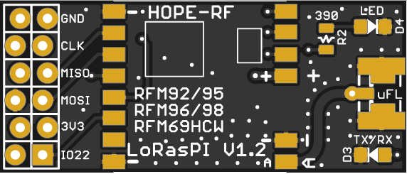
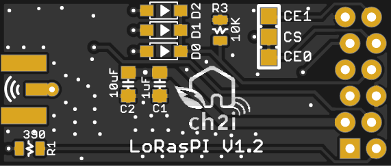
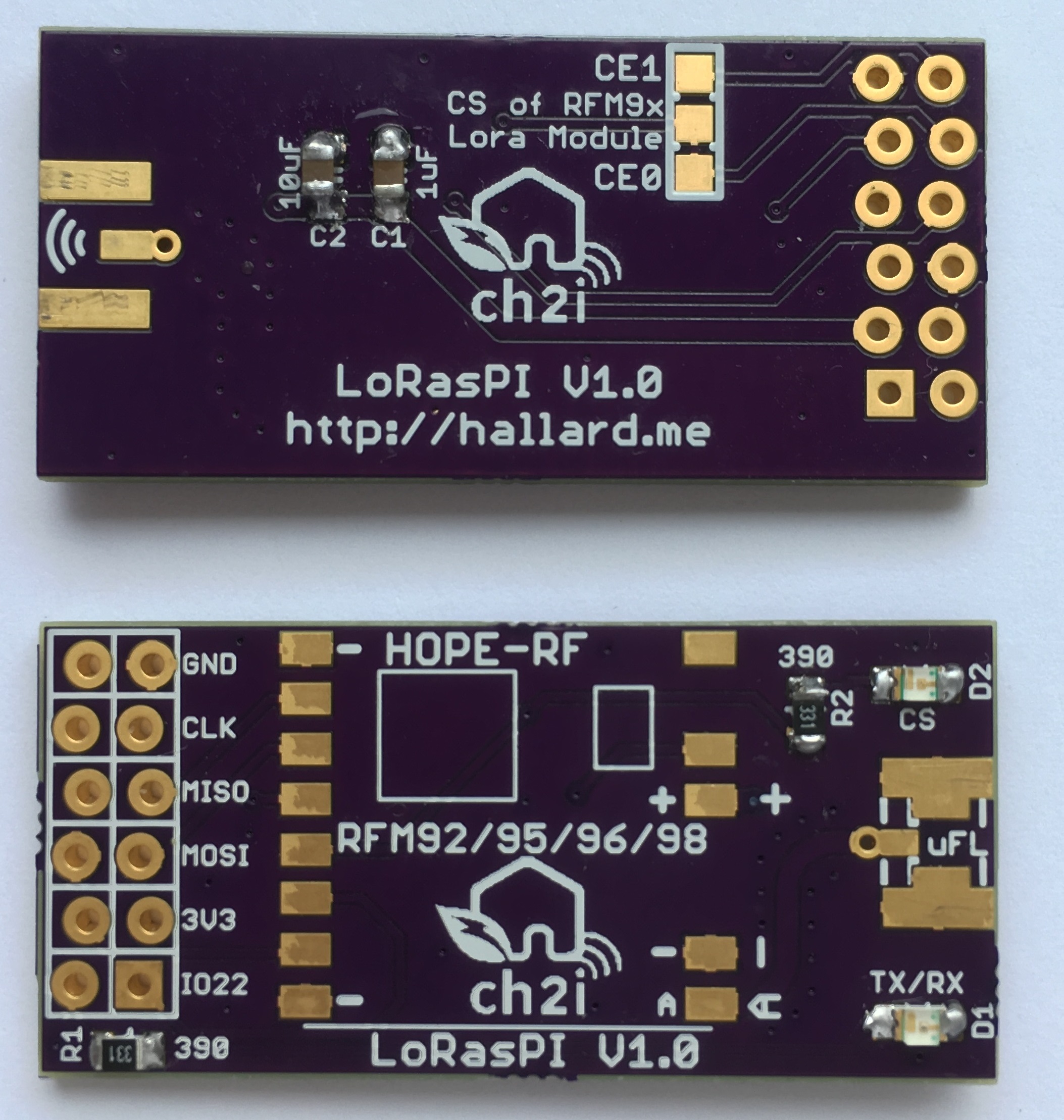
  • Placement for RFM92/95/96/98 Lora module or RFM69HCW classic module
  • Placement for choosing single Wire, SMA or u-FL Antenna type
  • 2 x LED LED for visual indication

New in Version 1.2a

  • V1.2 CS trace missing fixed

New in Version 1.2

  • R3 Error corrected, it's now a Pull Down
  • DIO5 connection to GPIO24 removed, not used
  • 2nd led is now connected to GPIO24 instead of CS line

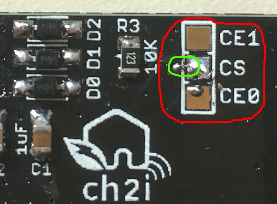
Error in V1.2, one small trace on CS (CE0 and CE1) signal is missing, fixed in V1.2a, I really apologize for this error, Eagle beginner error, ALWAYS place junction on schematic, because sometime it looks like connected but it's not!

Here is how to fix this V1.2 trace missing

Clean Way (experienced soldering user)

With a small cutter or tool remove silk to bring via copper visible, then solder a tiny wire from CS pad to Via as follow (in green) LoRasPI V1.2 Clean trace fix

Easy Way

Just route the CE0 or CE1 signal with a small wire dirctly to RFM9x module as follow LoRasPI V1.2 Easy trace fix 
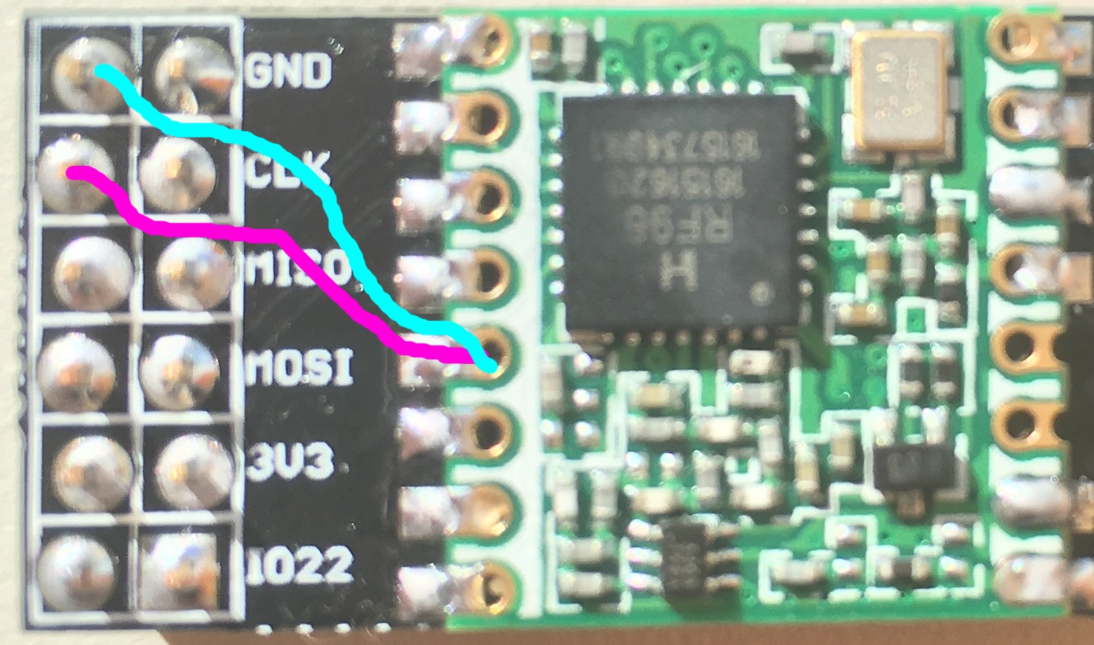
Use purple wire if you want to use CE0 and Cyan for CE1

New in Version 1.1

  • Reduced board width so it can be soldered on 2x40 pins connector to expose other GPIOs
  • Added DIO1 and DIO2 OR'ed with DIO0 and 1N4148 diode to conform LIMC stack
  • Better ground plane isolation
  • Added some via on RF part

I'm waiting now new V1.1 and V1.2 boards from OSHPark and PCBs.io, so I didn't fully tested V1.1/V1.2 yet, I will update ASAP.

I discovered a design error on V1.1, R3 resistor should be a pull down resistor and not a pull up, so you should not populate R3, do not place it, it's not a real problem since software will activate pull down of the BCM2835 controller but it's corrected in V1.2

I'm waiting boards V1.0 Boards arrived from OSHPark, all is working as expected (V1.0). so I didn't fully tested them yet, I will update ASAP.

Detailed Description

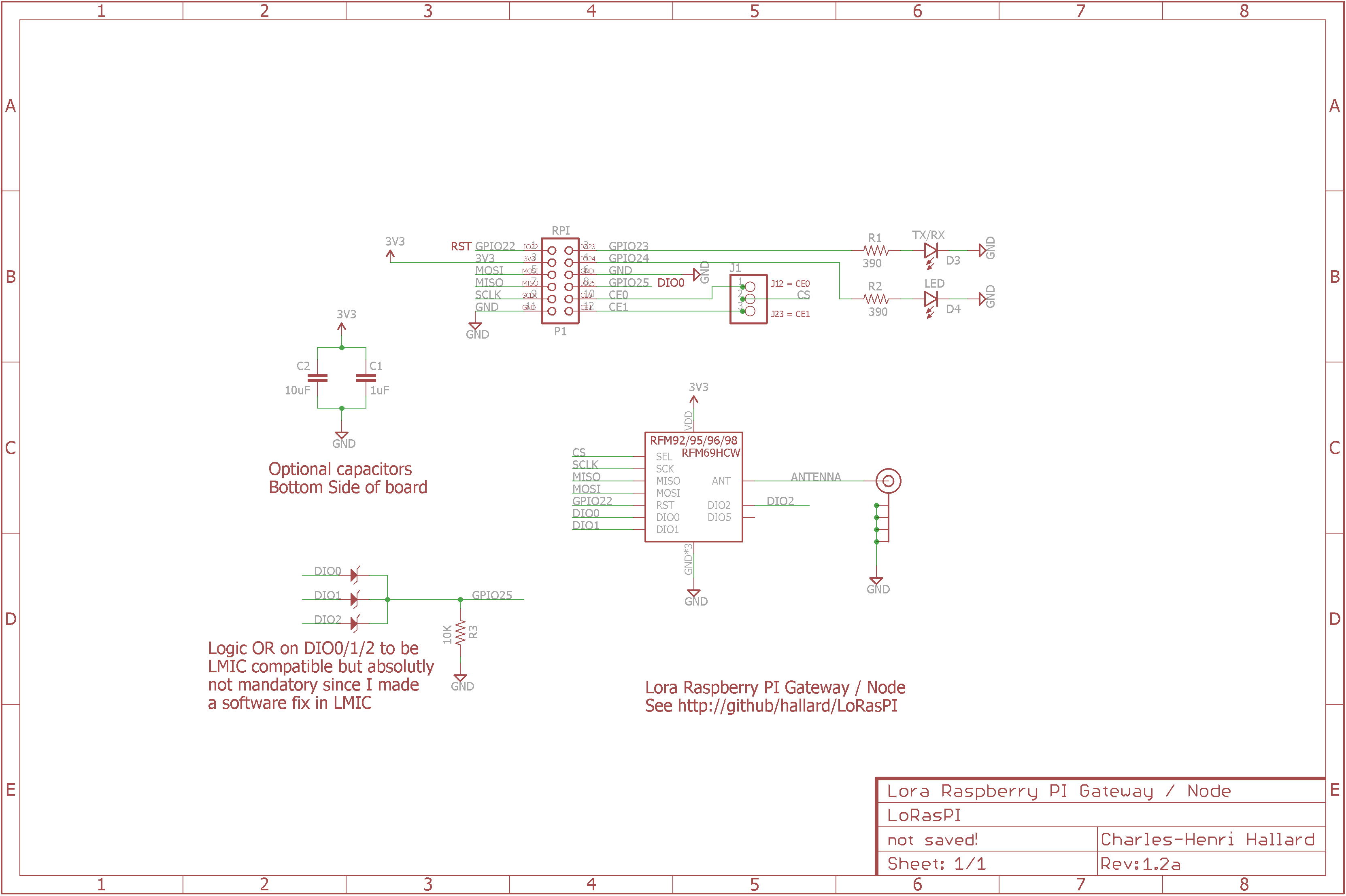
Look at the schematics for more informations.

SPI connexion is classic (MOSI/MISO/CLK), Chip Select can be connected to CE0 or CE1 of PI depending on bord solder PAD jumper. Take care that by default it's connected to CE0 (wired) so you don't have to do anything. If you want to connect to CE1 you'll need to cut CE0 trace on the PCB (on the solder pad).

Only One GPIO needed for DIO0/DIO1/DIO2 (OR made with 3 diodes and one resistor R3) that will make this board fully compatible with current LIMC implementation, even if I've done a software fix which works with no interrupt. Only Needed for Lora modules, if you're using RFM69HCW and and to use IRQ just place D0 and R3.

Other pins that may need be adapted into code (for example if you use TTN network gateway code) according to the following pinout This Single LoraWan Gateway has been tweaked and works right out of the box.

Detailed Description

Since V1.2

Raspberry PI   RFM9x Module 1
   GPIO22  <---->  Reset
   GPIO25  <---->  DIO0 OR DIO1 OR DIO2 (Hardware OR done with 1N4148 Diode and R3)

Raspberry PI   On Board LEDS
   GPIO23  <---->  LED D3 TX/RX
   GPIO24  <---->  LED D4 LED

V1.0 and V1.1

Raspberry PI   RFM9x Module 1
   GPIO22  <---->  Reset
   GPIO25  <---->  DIO0 OR DIO1 OR DIO2 (Hardware OR done with 1N4148 Diode and R3)
   GPIO24  <---->  DIO5 (Ready)

Raspberry PI   On Board LEDS
   GPIO23  <---->  LED D1 TX/RX
CE0 or CE1 <---->  LED D2 CS

Schematic

schematic

Boards

Top

Bottom

Assembled boards (V1.0)

Assembled

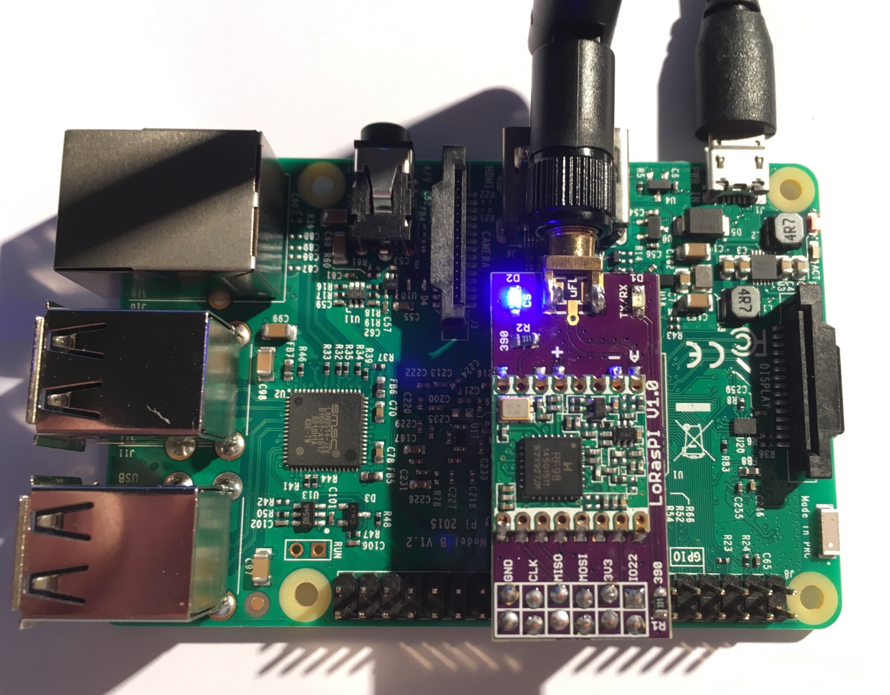
V1.0 connected to Raspberry PI.

LoRasPI plugged on PI

You can order the PCB of this board at OSHPARK (V1.1) or new V1.2a at PCBs.io. PCBs.io give me some reward when you order my designed boards from their site. This is pretty good, because I can use these rewards to create and design new boards and order boards for a discounted price and share new boards. So if you don't care about PCB manufacturer please use PCBs.io.

##License

You can do whatever you like with this design.

##Misc

See news and other projects on my blog

loraspi's People

Contributors

cyberman54 avatar hallard avatar the-alchemist avatar

Stargazers

 avatar  avatar  avatar  avatar  avatar  avatar  avatar  avatar  avatar  avatar  avatar  avatar  avatar  avatar  avatar  avatar  avatar  avatar  avatar  avatar  avatar  avatar  avatar  avatar  avatar  avatar  avatar  avatar  avatar  avatar  avatar  avatar  avatar  avatar  avatar  avatar  avatar  avatar  avatar  avatar  avatar  avatar  avatar  avatar  avatar  avatar  avatar  avatar  avatar  avatar  avatar  avatar  avatar  avatar  avatar  avatar  avatar  avatar  avatar  avatar  avatar  avatar  avatar  avatar  avatar  avatar  avatar  avatar  avatar  avatar  avatar  avatar  avatar  avatar  avatar  avatar  avatar  avatar  avatar  avatar  avatar  avatar  avatar  avatar  avatar  avatar  avatar  avatar  avatar  avatar  avatar  avatar  avatar  avatar  avatar  avatar  avatar  avatar  avatar  avatar

Watchers

 avatar  avatar  avatar  avatar  avatar  avatar  avatar  avatar  avatar  avatar  avatar  avatar  avatar  avatar  avatar  avatar  avatar  avatar  avatar  avatar

loraspi's Issues

Pin Mapping

Hi Charles,

first thank you very much for creating and sharing your PCB here!

I'd like to use your board (I ordered 8) like a breakout board.
I cant figure out the pin mapping on the left pin column of the LoRasPi 1.2a.
I'd like to connect those pins to an Arduino pro mini.

I made the following pin mapping:

LoRasPI RFM65 Arduino Pro Mini
GND GND GND
MISO MISO MISO
MOSI MOSI MOSI
3V3 VCC VCC
IO22 RST RST
D0 DIO 0 D4
D1 DIO 1 D5
D2 DIO 2 D7
CE0 ? ?
CS ? ?
CE1 ? ?

Is the map correct? Could you please correct any errors on LoRasPI col?

CS pin clarification

I'm using a LoRasPI PCB V1.2a with Single Channel LoRaWAN Gateway installed on a Raspberry Pi 4.
According to your schematic, NSS pin from lora module is connected to CE0 pin on the raspberry, so pin 10 on Wiring Pi.

On global_conf.json, you have for LoRasPi: "pin_nss": 8,
shouldn't be "pin_nss": 10?

What components are needed?

Hello, just a quick question, are there any specific details about the smd components needed. What size do the components need to be and what components are needed and what components do I not need (just for sending and recieving messages)?

Thanks,
LouisP

leds not working

Hi

I just build a LorasPI PCB V1.2a and installed Single Channel LoRaWAN Gateway on a Raspberry Pi 4. I think gateway is running ok, terminal shows

Trying to detect module with NSS=8 DIO0=6 Reset=3 Led1=4
SX1276 detected, starting.
Gateway ID: dc:b6:32:ff:fa:4c:a5:a3
Listening at SF7 on 868.100000 Mhz.
-----------------------------------
stat update: 2021-01-26 12:35:03 GMT no packet received yet
stat update: 2021-01-26 12:35:33 GMT no packet received yet

and i can see it online on TTN dashboard.

The problem is none of the leds light up, at least LED shouldn't be on?
I already checked led polarity or any missing solder/bad components.

Any idea?

Lots of packets

Hi Charles,

first of all, great work!

I've managed to construct this gateway and used your version of single packet forwarder, but I'm getting these continuous messages:

Packet RSSI: -157, RSSI: -103, SNR: 0, Length: 0 Message:''
rxpk update: {"rxpk":[{"tmst":2479877867,"freq":868.1,"chan":0,"rfch":0,"stat":1,"modu":"LORA","datr":"SF7BW125","codr":"4/5","rssi":-157,"lsnr":0.0,"size":0,"data":""}]}
Packet RSSI: -157, RSSI: -106, SNR: 0, Length: 0 Message:''
rxpk update: {"rxpk":[{"tmst":2479887927,"freq":868.1,"chan":0,"rfch":0,"stat":1,"modu":"LORA","datr":"SF7BW125","codr":"4/5","rssi":-157,"lsnr":0.0,"size":0,"data":""}]}
Packet RSSI: -157, RSSI: -104, SNR: 0, Length: 0 Message:''
rxpk update: {"rxpk":[{"tmst":2479898742,"freq":868.1,"chan":0,"rfch":0,"stat":1,"modu":"LORA","datr":"SF7BW125","codr":"4/5","rssi":-157,"lsnr":0.0,"size":0,"data":""}]}
Packet RSSI: -157, RSSI: -104, SNR: 0, Length: 0 Message:''
rxpk update: {"rxpk":[{"tmst":2479908300,"freq":868.1,"chan":0,"rfch":0,"stat":1,"modu":"LORA","datr":"SF7BW125","codr":"4/5","rssi":-157,"lsnr":0.0,"size":0,"data":""}]}

On the hardware I soldered the three DIO diodes and I think the rest is OK.

my config is:

pi@raspberrypi:~/single_chan_pkt_fwd $ sudo ./single_chan_pkt_fwd
server: .address = router.eu.staging.thethings.network; .port = 1700; .enable = 1
server: .address = router.eu.thethings.network; .port = 1700; .enable = 0
Gateway Configuration
JN GW ([email protected])
Dragino Single Channel Gateway on RPI
Latitude=0.00000000
Longitude=0.00000000
Altitude=10
Trying to detect module with NSS=8 DIO0=6 Reset=3 Led1=5
SX1276 detected, starting.
Gateway ID: b8:27:eb:ff:ff:63:c8:99
Listening at SF7 on 868.100000 Mhz.

stat update: 2019-09-06 12:28:26 GMT no packet received yet
Packet RSSI: -157, RSSI: -105, SNR: 0, Length: 0 Message:''

Can you help?

Thanks a lot!

Jorge

Antenna PCB trace

Hi,

I noticed that there are a split in the board ground plane bellow antenna PCB trace, near of ANT pin of the RF module. Is this OK ? Just another question. Has the antenna PCB trace, 50 ohm impedance ?

Regards

Seeking Guidance on LoRa Project - Need Help with Forwarding Packets

Hello ,

I hope this message finds you well. My name is Hirdesh Mewada, and I'm currently working on a LoRa project that involves forwarding packets between LoRa modules. I'm reaching out to the community for guidance and assistance with a specific aspect of my project.

Project Overview:
I'm working on a system where LoRa Module 1 forwards packets. In this setup, when a user is connected to Module 2 (linked to an ESP32 board and acting as an access point), and they enter a URL like "google.com" on their smartphone, I aim to have the request travel from the user's device to the ESP32, then to LoRa Module 2, reaching LoRa Module 1. Module 1 is connected to a Raspberry Pi, which, in turn, is connected to the internet. The Raspi should forward the request to the internet, retrieve the response, and send it back to its connected LoRa Module 1. Finally, Module 1 should forward the response back to Module 2, which can then be accessed by the user on their smartphone. The primary goal is to enable users to view basic text-based HTML websites through this LoRa network.

Specific Assistance Needed:
I'm seeking guidance or examples of code related to the following aspects:

Configuring LoRa communication at 868MHz.
Handling specific LoRa settings for packet forwarding.
Implementing the communication flow from the user device to the Raspi and vice versa.
I understand that your expertise and insights would be invaluable, and I appreciate any guidance or examples you can provide. If there are specific resources, code snippets, or documentation within the LoRa community that could be relevant to my project, I would be grateful for your direction.

Additional Information:

I'm using the pyLoRa library for this project.
and raspi 3b+ ,esp32 ,2 rfm96 modules
Thank you for taking the time to read my query. I look forward to any assistance you can offer.

Best regards,
HIRDESH MEWADA
[email protected]

OR gate for DIOx

On the schematics you show three Zener diodes for the OR logic gate between DIO0, DIO1 and DIO2. Must they be Zener or any other type should do? What are the characteristics needed for those diodes? I'm guessing they should be 3216 size from the PCB dimensions.

Thanks

Seeking Guidance on LoRa Packet Forwarding Project

Hello ,

I hope this message finds you well. My name is Hirdesh Mewada, and I'm currently working on a LoRa project that involves forwarding packets between LoRa modules. I'm reaching out to the community for guidance and assistance with a specific aspect of my project.

Project Overview:
I'm working on a system where LoRa Module 1 forwards packets. In this setup, when a user is connected to Module 2 (linked to an ESP32 board and acting as an access point), and they enter a URL like "google.com" on their smartphone, I aim to have the request travel from the user's device to the ESP32, then to LoRa Module 2, reaching LoRa Module 1. Module 1 is connected to a Raspberry Pi, which, in turn, is connected to the internet. The Raspi should forward the request to the internet, retrieve the response, and send it back to its connected LoRa Module 1. Finally, Module 1 should forward the response back to Module 2, which can then be accessed by the user on their smartphone. The primary goal is to enable users to view basic text-based HTML websites through this LoRa network.

Specific Assistance Needed:
I'm seeking guidance or examples of code related to the following aspects:

Configuring LoRa communication at 868MHz.
Handling specific LoRa settings for packet forwarding.
Implementing the communication flow from the user device to the Raspi and vice versa.
I understand that your expertise and insights would be invaluable, and I appreciate any guidance or examples you can provide. If there are specific resources, code snippets, or documentation within the LoRa community that could be relevant to my project, I would be grateful for your direction.

Additional Information:

I'm using the pyLoRa library for this project.
and raspi 3b+ ,esp32 ,2 rfm96 modules
Thank you for taking the time to read my query. I look forward to any assistance you can offer.

Best regards,
HIRDESH MEWADA
[email protected]

problem

Hi,

Did you test v1.2 please? I have two boards (one with rfm95w and another one with rfm68hcw) and both of them have problems. Transceivers are not detected by spi_scan., On both I connected D0 with 1N4148 and have R3 in place. Anything in particular I should check?

My RPi3 is detecting other boards with rfm95w with no problem.

Thanks
Alex

Pin header specifications

Do you have a part number for the pin header you are using? I'm having trouble finding a suitable header with staggered pins.

Recommend Projects

  • React photo React

    A declarative, efficient, and flexible JavaScript library for building user interfaces.

  • Vue.js photo Vue.js

    ๐Ÿ–– Vue.js is a progressive, incrementally-adoptable JavaScript framework for building UI on the web.

  • Typescript photo Typescript

    TypeScript is a superset of JavaScript that compiles to clean JavaScript output.

  • TensorFlow photo TensorFlow

    An Open Source Machine Learning Framework for Everyone

  • Django photo Django

    The Web framework for perfectionists with deadlines.

  • D3 photo D3

    Bring data to life with SVG, Canvas and HTML. ๐Ÿ“Š๐Ÿ“ˆ๐ŸŽ‰

Recommend Topics

  • javascript

    JavaScript (JS) is a lightweight interpreted programming language with first-class functions.

  • web

    Some thing interesting about web. New door for the world.

  • server

    A server is a program made to process requests and deliver data to clients.

  • Machine learning

    Machine learning is a way of modeling and interpreting data that allows a piece of software to respond intelligently.

  • Game

    Some thing interesting about game, make everyone happy.

Recommend Org

  • Facebook photo Facebook

    We are working to build community through open source technology. NB: members must have two-factor auth.

  • Microsoft photo Microsoft

    Open source projects and samples from Microsoft.

  • Google photo Google

    Google โค๏ธ Open Source for everyone.

  • D3 photo D3

    Data-Driven Documents codes.