Giter VIP home page Giter VIP logo

livolo-firmware's Introduction

Firmware for Livolo light switches

Livolo control video

I wanted to add on/off feedback and wired remote control to a Livolo switch. Their brain is a PIC16F690, but unfortunately the chip comes code protected, so I had to write this firmware from scratch.

Features:

  • Serial communication.
  • On/off feedback via UART
  • Remote control via UART
  • 2 wires (TX/RX + GND) for simplex, 3 wires (TX, RX, GND) for duplex comms.
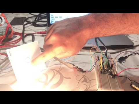
  • Easy to modify: all the extra wires can be soldered to the empty RF through-hole header J6.

Pull requests welcome

This is work in progress. I plan to use this and I don't want to set my house on fire, so either if you want to study how the switch works internally or fork it to further work on it, I'd love to hear from suggestions or improvements!

Supported boards:

  • VL-C701X-2 VER: C0 (1-gang, 1-way, no RF, EU version)

Should be easy to work with this, too:

  • VL-C702X-2 VER: C1 (2-gang, 1-way, no RF, EU version)

Note that there is no guarantee that buying from these links will get you those versions since they seem to change designs often.

Working principle

The Livolo switches use a PIC16F690 to detect slight capacitance changes on a glass plate when a finger is pressed against it. The working principle is described in Microchip's AN1101 (recommended read). The differences with regards to the application note are:

  • The output of the C2 comparator is connected to the clock input of Timer 0 instead of Timer 1.
  • The 1/3 voltage divider is replaced with the internal 0.6V reference.
  • The 2/3 voltage divider is replaced with the internal VR reference, which can be configured via VRCON.

How to use

Once you flash the PIC, there is no coming back!

The Livolo PIC has its CP bit on, which means its flash is unreadable, and thus you can't make a backup copy of the pre-installed firmware.

Because of this, I recommend replacing the PIC with a blank one. This way you still have a working chip with the original behavior to roll back to.

You need MPLAB X IDE + XC8 compiler. Load up the project, compile and flash.

config.h contains a few flags that can be finetuned, ie. the trip and release threshold values.

Serial connection

Okay, first off the ground traces of the Livolo board (including PIC's GND) are actually referenced to the live wire. Repeat: GND IS ACTUALLY LIVE, so the challenge here is to be able to talk to a PC without electrocuting yourself.

In order to pull data safely from the circuit there are two options:

Battery + inverter / isolation transformer

I won't go into much detail because you should know what you are doing if you want to play with 220V. But if you want to get serial data out of the PIC or just use an oscilloscope to probe the signals, one option is to isolate the Livolo power from the mains supply.

I used a cheap (150W) car battery inverter powered by a 3S LiPo because that's what I had at hand. You can use an isolation transformer as well. If you reference the PIC's Vss to ground via the scope's alligator clip, the whole board now becomes referenced to the real ground and it's a bit safer to play around with. Just don't touch the live and neutral wires of the Livolo.

Optocouplers

I also tried this, but personally I find the battery + inverter easier and safer while debugging.

Anyhow, the idea is to use optocouplers. But apparently in the optocouplers world you can only have two of a) cheap, b) low current, c) fast. I had a few 6N137 at hand so I used that. They are cheap, they are fast, but they swallow too much current for Livolo's puny power supply.

So I had to add a battery to provide the extra oomph to light up the diode of one of the OCs and drive the collector of the other, yuck!

schematic

Of course this is only valid for debugging to get data out of the PIC. The battery thing makes this unfeasible for a permanent installation and I'm still looking for other solutions.

Note that I had to bitbang pin RB4 on the PIC for TX out because that PIN is exposed on the empty J6 header along with RX and Vss. That way we have everything we need in J6, which it's through hole and easier to solder on.

If you choose to use the real TX pin, you can track it down to a couple of empty resistor pads, but I found it harder to solder a wire on an SMD pad securely and thus I preferred the bitbang way even if it makes transmission slower.

livolo-firmware's People

Stargazers

 avatar  avatar  avatar  avatar  avatar  avatar  avatar  avatar  avatar  avatar  avatar  avatar  avatar  avatar  avatar  avatar  avatar  avatar  avatar  avatar

Watchers

 avatar  avatar  avatar  avatar  avatar  avatar  avatar  avatar

livolo-firmware's Issues

unknown type name 'bit'

Hi,

I have loaded the project and when i tried to compile i got the error: In file included from uart.c:4:
./uart.h:15:1: error: unknown type name 'bit'

I'm using MPLAB X IDE 5.05 with XC8 installed.

what could be the issue here?

*** Update ***
I found the problem. The C Standard setting in XC8 Global options was set to C99. Moved it to C90 and it works perfectly. Now my only problem is that when i want to program the livolo switch, i get the error: "Cannot program a production build to a debug header." .. Hmm i need to do more digging...

*** Update 2 ***
The problem was occuring because the debug header was enabled in my config. I disabled it by going to Project Properties -> Configuration -> Under "Supported Debug Header" I selected "None".
-> Make and Program device and everything was ok.

This issue can now be closed as the programming works fine. I will open another issue with another problem i'm facing after flash, in the hopes of also helping other people in the future.

Thanks,
Regards.

Not an issues, just to say thanks and a question for debugging

I just wanted to say thanks for doing all the investigation on the light switches.

It did a similar project for the Livolo thermostats https://github.com/tobiaswaldvogel/livolo-thermostat and now I'm also considering writing a new firmware for the Zigbee version of the Livolo Light switches, which is also totally buggy and does not work with any standard Zigbee product.
Another issue I noted with the 2 gang version is, that the sensitivity of the 2nd sensor is very bad. You have to touch exactly the center and preferably with the thumb, whereas the 1st one work just fine. So the idea is to fix this as well.

You documentation is a really great help for getting started.
One thing I wanted to ask is, how you did the debugging. For the thermostat I didn't want to unsold the PIC and use a debug header, because it is easy to break some of the SMD pins. I just used the display for debug output (e.g. display a 4 digit hex as 4 decimal numbers from 0 to 15, one after each other).
Probably the easiest way for the switches (at least for the Zigbee part) is just powering the board from the PICkit and use your UART bit-bang code on RB4 for debug output. I guess.

Change switch on push button

Hello Jamarju

Is it possible to change the code that the relays no longer switch but only make a short pulse ?
Unfortunately, I am not so experienced in the programming of the PIC

Blue SMD is always on

I know that this project is for VL-C701X-2 VER: C0 (1-gang, 1-way, no RF, EU version) version but i'm raising this issues as i have a different board and i think that we can help people with different hardware types from Livolo, in the future as we can use this issue also as a guide. I tried to buy that version but it wasn't available so i got he VL-C601-2 (1-gang, 1 way).

The issue that i'm facing at the moment is that the Blue led is always On.

Question 1: How do i change what led is on and what led is off. I already took a look at the PCI 16f690 and i can see that the blue led is connected to Pin 13 (RB4/AN10/SDI/SDA). I will try to draw a circuit diagram and update this issue later.

Question 2: For my project i don't plan to use the 220v part at all, all i want is to have it powered up and communicating with either a nodeMCU (esp8266) or an arduino mini. My second question is, what and how should i detect from the switch that the state of the switch has changed. I tried to connect the RF Tx and Rx pins to the Arduino and opened up a serial port with a 57600 baudrate and Serial.read(); in the loop() method, but all i got were special characters (like a sqare, romb and other symbols that don't mean anything) and i couldn't read or understand anything from it. Show what should i expect to be delivered on the Serial ?

*** Update 1 *** : I have tried to reproduce the diagram of VL-C601-2 with as much detail as i could.
I attached a picture of the diagram here(Please note that it might be incorrect and i might need a second look at the wires.).

For me it makes no sense on how the LED should operate, and furthermore how can i adapt your code to work with the 2 LEDs (i can power them from an Arduino if needed).

(However, i understand now why the Blue LED is always powered on when i power the board from the PICKIT3 using J5 RF connector)
livolo-vl-c601-2-c0

Thanks.

Recommend Projects

  • React photo React

    A declarative, efficient, and flexible JavaScript library for building user interfaces.

  • Vue.js photo Vue.js

    ๐Ÿ–– Vue.js is a progressive, incrementally-adoptable JavaScript framework for building UI on the web.

  • Typescript photo Typescript

    TypeScript is a superset of JavaScript that compiles to clean JavaScript output.

  • TensorFlow photo TensorFlow

    An Open Source Machine Learning Framework for Everyone

  • Django photo Django

    The Web framework for perfectionists with deadlines.

  • D3 photo D3

    Bring data to life with SVG, Canvas and HTML. ๐Ÿ“Š๐Ÿ“ˆ๐ŸŽ‰

Recommend Topics

  • javascript

    JavaScript (JS) is a lightweight interpreted programming language with first-class functions.

  • web

    Some thing interesting about web. New door for the world.

  • server

    A server is a program made to process requests and deliver data to clients.

  • Machine learning

    Machine learning is a way of modeling and interpreting data that allows a piece of software to respond intelligently.

  • Game

    Some thing interesting about game, make everyone happy.

Recommend Org

  • Facebook photo Facebook

    We are working to build community through open source technology. NB: members must have two-factor auth.

  • Microsoft photo Microsoft

    Open source projects and samples from Microsoft.

  • Google photo Google

    Google โค๏ธ Open Source for everyone.

  • D3 photo D3

    Data-Driven Documents codes.