Giter VIP home page Giter VIP logo

ethersweep's Introduction

Ethersweep Logo

Ethersweep

An Open Source Ethernet controllable stepper motor. Easy interfacing with JSON and UDP from any device on the network in any language you choose.

As there is quite some interest in buying a controller, please fill out this form to help me better understand what Ethersweep would be used for https://forms.gle/FLgfvCP1hjCCp2636

More media/press material: https://drive.google.com/drive/folders/1qrk8QeEkzJ8hkr-H0x3y7xxhLTKhMb_F?usp=share_link

NEWS NOTE: Ethersweep is a project still in development. If you plan to order boards for yourself, you can, but expect it to take some work to get everything running! If you have any questions, please write me on Discord: https://discord.com/invite/rerCyqAcrw or LinkedIn: https://www.linkedin.com/in/neumi/ If you need a custom assembly code or have a special use case in mind, contact me. The latest running version is in the production directory. It is now an STM32f103 version with TMC2209 stepper driver. The assembly files contain LCSC part numbers and can be directly ordered at JLCPCB including assembly. Only some THT parts and SMD AS5600 encoder must be soldered by hand.

linear axis

What it does

Ethersweep is a motor controller for NEMA17 stepper motors that can be controlled from normal Ethernet networks. This means that you will be able to control motion from normal computers (laptop/server/raspberrypi), mobile devices, microcontrollers, PLCs and any other machine that is capable of sending UDP messages. On top you can control as many motors as you like because every motor gets an IP address from the DHCP server on your network. You can also connect End and E-Stops to the controller. Sensor data like encoder feedback, voltage, running and button states can also be requested via network requests.

All you need is a network and power between 5v and 30v. PCB Photo

What it needs

Every motor has to be connected to an Ethernet network (optimally with DHCP) and a power supply between 5...30V. USB can be used for programming the controller with new firmware. End and E-Stops can be connected with JST3-pin connectors. To send instructions to Ethersweep you just send a JSON-encoded message via UDP to the controller's IP and port.

Features:

  • W5500 Ethernet controller
  • STM32f103 Microcontroller @ 72MHz
  • Trinamic TMC2209 Stepper motor driver
  • AS5600 magnetic rotary encoder
  • XT30 power connector
  • Oled 128x32 Display
  • USB programmable
  • Inputs for E-Stop and End-Stop
  • Reset button
  • Fits on a NEMA17 stepper motor
  • standard RJ45 network connector

Display content

How to get started:

Build an (or multiple) Ethersweep controller. All manufacturing/assembly files work with JLCPCB and only some easy THT soldering is needed when the boards arrive. The code is available in the repository.

Connect your Ethersweep controller to your network via ethernet and connect to a 5.5...30V power source. Stick an encoder magnet (radial magnetized) on a NEMA17 motor shaft and connect the controller to the four M3 screws of the motor. Once connected to power and Ethernet, it searches for an IP address using DHCP. When an IP is found, the controller shows it on the display and it's ready to use. When no IP is found, it defaults to 192.168.1.111 if available. (It is recommended to use DHCP)

Now you can use the Python script to control the motor.

PCB raw B cad rotation pcb layout

Using Python to control a stepper motor:

import socket
import json

IP_MOTOR = "192.168.1.185" # ethersweep IP (change to motors IP)
UDP_PORT = 8888 # ethersweep port


def drive_motor(steps, speed, direction, mode, motor_ip):
    json_data = json.dumps({'steps': steps, 'speed': speed, 'direction': direction, 'mode': mode})
    message = json_data.encode()
    sock = socket.socket(socket.AF_INET, socket.SOCK_DGRAM)
    sock.sendto(message, (motor_ip, UDP_PORT))


drive_motor(100, 9500, 1, 32, IP_MOTOR) # this will spin the motor 100 steps

Video:

LINK TO VIDEO

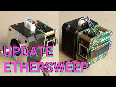
Follow the project on hackaday.io: https://hackaday.io/project/187187-ethersweep

Upcoming Features:

  • improved Broadcast mode + motor synchronization for multiple motors
  • motor servo mode
  • TMC2209 software interface
  • scheduler

Big thanks to the sponsors of this project!

sponsor_banner

ethersweep's People

Contributors

neumi avatar

Stargazers

 avatar  avatar  avatar  avatar  avatar  avatar  avatar  avatar  avatar  avatar  avatar  avatar  avatar  avatar  avatar  avatar  avatar  avatar  avatar  avatar  avatar  avatar  avatar  avatar  avatar  avatar  avatar  avatar  avatar  avatar  avatar  avatar  avatar  avatar  avatar  avatar  avatar  avatar  avatar  avatar  avatar  avatar  avatar  avatar  avatar  avatar  avatar  avatar  avatar  avatar  avatar  avatar  avatar  avatar  avatar  avatar  avatar  avatar  avatar  avatar  avatar  avatar  avatar  avatar  avatar  avatar  avatar  avatar  avatar  avatar  avatar  avatar  avatar  avatar  avatar  avatar  avatar  avatar  avatar  avatar  avatar  avatar  avatar  avatar  avatar  avatar  avatar  avatar  avatar  avatar  avatar  avatar  avatar  avatar  avatar  avatar  avatar  avatar  avatar  avatar

Watchers

 avatar  avatar  avatar  avatar  avatar  avatar  avatar  avatar  avatar  avatar  avatar  avatar  avatar  avatar  avatar  avatar  avatar  avatar  avatar  avatar  avatar  avatar  avatar  avatar  avatar  avatar  avatar  avatar  avatar

ethersweep's Issues

Design feedback

I just saw the youtube video you posted and it looks like you've made a lot of good progress on this project. I decided to check out your schematic/layout and here's some feedback. I just did a quick review of it, so if I got an old design let me know (I went dev and the latest "complete looking" board).

I did not review the firmware, but I do have some STM experience so maybe I'll be inspired to do that later.

  • You should start using 0201 components for all your smaller cap's (anything below 100nF) and small resistors (pull-ups, 0 ohm jumpers, etc). Most fab places do not charge extra anymore for this size (jlcpcb hasn't for several years) and those parts can be cheaper sometimes than 0402's. I realize reworking 0201's is tough, but for all the little bypass caps you probably won't be reworking those. Plus the design seems more refined now.

  • 100mil is standard for headers, but they do make 50mil headers. Might save you some room if you're doing a multi-board thing (you make the LCD board right?)

  • Kicad now supports multiple sheets in version 7.0, so you could split up the schematic into logical blocks (maybe power, uC/com/display, motor control). The board isn't too complex though, so it's kind of a toss-up.

  • The routing around C38 is really tight, but you have tons of room on the back layer below it. Same with the motor controller (C40, D6, D5, C11 could all go on the back side. keep the 100n bypass caps on the same side)

  • J2 didn't load for me, but is this just a 2-pin terminal block? (the green connectors with screw adjusts)

  • Do you really need an 8MHz crystal? The STM32 has a decent (+/- 2% over full temp range) RC oscillator called the HSI that runs at 8MHz. This would save you a bit of cost and a "giant" part in the middle of your board.

  • If you want an easy flashing header that adds zero cost, look into tag-connect. Another option would be writing a little bootloader in the STM32 that has just enough code to do ethernet IO & flash memory. Then you could do all the programming entirely with ethernet (you flash the bootloader via a header, then upgrades are done via ethernet).
    ** To do this you can create a separate linker file and relocate your code somewhere else in memory. The STM32 will boot into the bootloader, the bootloader will check the "upgrade image" and if it's okay boot from it. Then you just need a mechanism to revert back to the upgrade image if needed (push button maybe?)

  • You should look into adding ESD/EMI protection to all exposed ports and accessibly supply rails (probably 5V, must you can skip 3.3V). There are single chip options for USB and you'll need them for the stepper motor driver. The TMC2209 has example protection circuitry in the datasheet that you should have. Aim for at least 16kV rating on the ESD stuff (32kV would be better, but it isn't required).

Crazy ideas:

  • Switch to USB-C for power and get one chip that drives the CC1/2 lines so you can get 28-48V via USB power delivery. Yeah, I old PD 3.0 doesn't go past 20V, but the new USB PD standard supports 28V/36V/48V at up to 5A. You can still use the DP/DM lines for the UART. Here's a chip that'll do PD 3.1 (28V): https://en.hynetek.com/pddrp.html HUSB311

  • I know you just switched to a new uC, but have you looked at the RPI Pico? It has a dual core M0 running at >100MHz and it's cheaper than the STM ($0.97 vs $1.41 at JLCPCB, although you'll need a crystal & flash for it - so probably same cost). The C/C++ API for the RPI Pico is really well tested and you can probably port a lot of code. No motor controller though, so you'll probably need to dedicate one core to the motor/feedback sensor.

  • For the ethernet control format, how about supporting a queue of commands with precise timing? You could then build up a small language of motor operation and queue them all up on the controller (ex: sweep 20 degrees at x steps/s, wait 40ms, repeat 10 times)

fix JLC CPL files

Every second update of JLCPCB services crashes the CPL and or BOM files. This might be fixed in the CSVs or in kicad.

POE support?

Really nice project. I've been looking for something like this for a while.

I know you're short on space, but did you consider adding POE support? You can get modules that do most of the work for you (Ag9912 or Ag9924) and you might be able to squeeze one in between the two boards with some longer standoff connectors.

The other thing I was wondering is why you didn't use a 4-layer PCB. The cost increase is fairly minimal these days (looks like jlcpcb adds ~$2-$3 per board for qty=5, but most of your cost is in components) and your signal routing would be a lot cleaner. For signal integrity it's always helpful to have one continuous ground plane layer, although you ended up achieving almost that on the flooded back layer.

Consider using internal voltage reference

Quick look through the schematic I noticed your voltage reading assumes a 3.3V ADC reference voltage.
Just be aware that your ADC measurements are then limited to the accuracy of your supply voltage.

You probably don't need any high accuracy ADC measurements, I just recently ran into a problem where I did and I wished I'd prepared my PCB for it instead of having to do a re-spin.

The STM32F103 (and F107) have a built in 1.2V, 100ppm/K. It is however +5% -3% for initial accuracy going with the min/max spec so, meh.
I don't have any experience with how close to the typical 1.2V it usually is.

Alternatively an external vref could be used.

Also, remember to check the errata for the MCU you're using when considering this stuff... Yes I also got burned there :P
(The F103 doesn't seem to have any vref related errata, tho a short blurp about ADC ch0 generating a 10ns 150mV blip in certain usecases)

Higher voltages

Apologies if this is not the correct way to ask a question of the project team. What modifications would be required to allow this to be used with a higher voltage power supply & a larger stepper motor, like a Nema34?

Daisy chain connection

Note:
This is purely an enhancement Idea.

Idea:
In my opinion the addition of a second RJ-45 port, along with the necessary switch on the PCB - or an Additional board - would improve the longterm usability, since it would make it possible to daisy chain the servos.

Reasoning:

  • Daisy chaining and on device switching would ease up wiring in most cases.
  • cleaner cable management specially for larger setups could be achieved.
  • It would negate the necessity to use an external switch.
    Thus it would ad the possibility to run it from a usual SBC - like the RPi-4 or similar - as these often only have one RJ-45 port.
    Further it could improve runtime for remote controlled robots - since the number of consumers are reduced.

Possible issues:

  • It would take a lot of space on the PCB, that already seamed to be crowed.
  • The extra cost in research, engineering, manufacturing might not justify the benefits for simpler setups (cables and routers are cheap)

make use of w5500 interrupt

Interrupt should be read and processed.
May need a hardware change to process on the interrupt pin on atmega328.

Any plans for Nema 23 ?

Hi ,

Thanks a lot for making this project available to all of us ,indeed quite a lot of handwork goes in making such projects , and any such work is highly appreciated , however do you have any plans to make ethersweep for Nema 23/24 closed loop motors ?

Rethink connectors

Micro USB -> USB C
Sensor/EndStop/Estop connectors should be 3-pin with gnd, vcc and sens

USB C & USB PD

Add USB C and USB PD.
Maybe get rid of xt30, maybe keep it.

build scheduler

Different tasks have to run at the same time. Like: Display refresh, sensor refresh, motor drive, network buffer fetch ...
Build a scheduler that knows about different priorities in different situations/modes and do the associated tasks accordingly.

Change the architecture accordingly. Don't break too much old code please. (but also make it future proof)

see https://github.com/Neumi/ethersweep/tree/scheduler

pdf schematics

I just tried to open your kicad files, but it fails with lots of libraries missing.
Most IC's just show up as "??"
maybe it's fault of my old debian 10... anayway...

would be great to have a schematics drawing as a pdf, without any elaborated dependencies to be fulfilled


btw
I'm just in the process to order some (~10 ) units.
anybody interested in bundling order volume?

EtherCAT option

Hi! Love the project. I saw some comments on the YouTube video which included your view on EtherCAT as

EtherCAT is closed source. You have to buy the IC/ASIC from Beckhoff for approx. 20€ p.p. You also have to buy product into the EtherCAT community. (Nothing for an open-source project). Ethercat is on a lower Ethernet OSI layer and can, therefore handle requests much faster before it is even decoded. Also you need specialized switches and routers. All of this makes this hard to use and expensive, if you just want to setup a tiny experimental assembly. Of course, if you need very deterministic/hard timing you could/should use i.e. Beckhoff servos. But they are 500€ pp + switches + very expensive cables ... And if you have limited space (robot, small machine) you don't need the big distribution boards etc. A cheap BotBlox switch is enough ;)

While I can certainly understand that viewpoint, I'm opening this issue in hope I can persuade you. Offering an EtherCAT model solves a couple of issues that are otherwise challenging in machine builds:

  1. Addressing
    Since slave addresses are based on cabled positions, no DHCP or IP configuration is required. You plug your topology together and can address it based on how it is connected or via MAC.
  2. Cabling and switching
    Since slave IC's include a two or three port "switch", no dedicated switch is required (daisy chaining)
  3. Reliability in the face of excess traffic
    Due to EtherCAT's mailboxing design, a slave cannot be overwhelmed in the same way that a Microcontroller reading UDP other packets can be. The ASIC also offloads much of the complexity, allowing a lower cost micro to deliver better functionality.

The LAN9252/LAN9253 is regularly available for less than $10 (+ a second magjack) and replaces the cost of the ethernet MAC. I imagine this would also cut the microcontroller and OLED cost, and reduce firmware complexity.

The ASIC is the only licensed component. There are no special cables. Switches are not required since each slave is daisy-chained. Routers are not relevant, since it is not a routed protocol. There are $0 and open source controllers available for Windows and Linux (1, 2).

There are, of course, other benefits:

  1. Time synchronization
  2. Interoperability with PLC's, other controllers, and other motors
  3. Safety without secondary cabling

I'm not associated with Beckhoff or any similar EtherCAT manufacturer. I've just been burned a couple times by Ethernet embedded devices that have tried to re-implement their own automation protocol, and each time have been burned by addressing or communication reliability. EtherCAT and CANBUS are dominant due to their merits.

Rework JSON instrucion set

Currently, the JSON structure is not used to its full potential.
The commands should use more depth of the json tree and add more modes like settings and request modes.

Release version

Can you kindly add release versions so one would know if that is still beta (0.1.0) or actually released (1.0.0) and start using it.

Thanks for the project !

Recommend Projects

  • React photo React

    A declarative, efficient, and flexible JavaScript library for building user interfaces.

  • Vue.js photo Vue.js

    🖖 Vue.js is a progressive, incrementally-adoptable JavaScript framework for building UI on the web.

  • Typescript photo Typescript

    TypeScript is a superset of JavaScript that compiles to clean JavaScript output.

  • TensorFlow photo TensorFlow

    An Open Source Machine Learning Framework for Everyone

  • Django photo Django

    The Web framework for perfectionists with deadlines.

  • D3 photo D3

    Bring data to life with SVG, Canvas and HTML. 📊📈🎉

Recommend Topics

  • javascript

    JavaScript (JS) is a lightweight interpreted programming language with first-class functions.

  • web

    Some thing interesting about web. New door for the world.

  • server

    A server is a program made to process requests and deliver data to clients.

  • Machine learning

    Machine learning is a way of modeling and interpreting data that allows a piece of software to respond intelligently.

  • Game

    Some thing interesting about game, make everyone happy.

Recommend Org

  • Facebook photo Facebook

    We are working to build community through open source technology. NB: members must have two-factor auth.

  • Microsoft photo Microsoft

    Open source projects and samples from Microsoft.

  • Google photo Google

    Google ❤️ Open Source for everyone.

  • D3 photo D3

    Data-Driven Documents codes.