Giter VIP home page Giter VIP logo

aioc's Introduction

AIOC

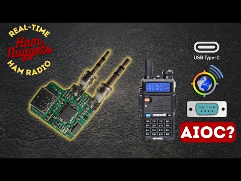
This is the Ham Radio All-in-one-Cable. It is currently still being tested! Please read this README carefully before ordering anything.

AIOC with Wouxun and Direwolf

What does it do?

The AIOC is a small adapter with a USB-C connector that enumerates itself as a sound-card (e.g. for APRS purposes), a virtual tty ("COM Port") for programming and asserting the PTT (Push-To-Talk) as well as a CM108 compatible HID endpoint for CM108-style PTT (new in firmware version 1.2.0).

You can watch the videos of the Temporarily Offline and HAM RADIO DUDE YouTube channels below.

All In One Cable AIOC - Ham Nuggets Season 4 Episode 8 S04E08 Your BAOFENG Programming Cable Sucks! - Get This! - AIOC All in One Cable

Features

  • Cheap & Hackable Digital mode USB interface (similar to digirig, mobilinkd, etc...)
  • Programming Cable Function via virtual Serial Port
  • Compact form-factor (DIY overmolded enclosure is currently TBD)
  • Based on easy-to-hack STM32F302 with internal ADC/DAC (Programmable via USB bootloader using DFU)
  • Can support Dual-PTT HTs

Compatibility

Software

Tested Radios (so far)

  • Wouxun UV-9D Mate (CHIRP + APRS)
  • Baofeng UV-5R (CHIRP + APRS)
  • BTECH 6X2 (CHIRP)

Top side of PCB

How To Fab

  • Go to JLCPCB.com and upload the GERBER-k1-aioc.zip package (under kicad/k1-aioc/jlcpcb)
    • Select PCB Thickness 1.2mm (that is what I recommend with the TRS connectors I used)
    • You may want to select LeadFree HASL
    • Select Silkscreen/Soldermask color to your liking
  • Check "PCB Assembly"
    • PCBA Type "Economic"
    • Assembly Side "Top Side"
    • Tooling Holes "Added by Customer"
    • Press Confirm
    • Click "Add BOM File" and upload BOM-k1-aioc.csv
    • Click "Add CPL File" and upload CPL-k1-aioc.csv
    • Press Next
    • Look Through components, see if something is missing or problematic and press Next
    • Check everything looks roughly good (rotations are already baked-in and should be correct). Save to Cart

This gives you 5 (or more) SMD assembled AIOC. The only thing left to do is soldering on the TRS connectors (see here). The total bill should be around 60$ US for 5 pieces plus tax and shipping from China.

Note that the following message from JLCPCB is okay and can be ignored.

The below parts won't be assembled due to data missing.
H1,H2 designators don't exist in the BOM file.
J2,D3,D4,R17 designators don't exist in the CPL file.

Note for people doing their own PCB production: I suggest using the LCSC part numbers in the BOM file as a guide on what to buy (especially regarding the MCU).

How To Assemble

This is the process I use for building. See photographs in images folder.

  • You need to use Monacor PG-204P and PG-203P or compatible TRS connectors (2 solder lugs and a big tab for the sleeve connection). Adafruit products 1800 and 1798 are confirmed to work as well.
  • Cut the 2.5mm and 3.5mm TRS sleeve tab where the hole is located
  • Put both TRS connectors into the 3d-printed solder guide (or a cheap HT that you don't mind potentially damaging). Make sure, that they are seated all the way in. If the holes in the solder guide are too small, you can ream them using a 2.5mm and 3.5mm drill bit.
  • Insert the AIOC PCB into the solder guide
  • Solder sleeve tab on the back side for both TRS connectors first
  • Turn around PCB and solder remaining solder lugs
  • Optionally you can 3D print a case for your AIOC. This model has been designed by a third party but is confirmed to work with the AIOC.

How To Build

For building the firmware, clone the repository and initialize the submodules. Create an empty workspace with the STM32CubeIDE and import the project.

  • git clone <repositry url>
  • git submodule update --init
  • Start STM32CubeIDE and create a new workspace under <project-root>/stm32
  • Choose File->Import and import the aioc-fw project in the same folder without copying
  • Select Project->Build All and the project should build. Use the Release build unless you specifically want to debug an issue

How To Program

Initial programming

The following steps are required for initial programming of the AIOC:

  • Short outermost pins on the programming header. This will set the device into bootloader mode in the next step. Shorting pins for bootloader mode
  • Connect USB-C cable to the AIOC PCB
  • Use a tool like dfu-util to program the firmware binary from the GitHub Releases page like this:
    dfu-util -a 0 -s 0x08000000 -D aioc-fw-x-y-z.bin
    
    Note that a libusb driver is required for this. On Windows there are additional steps required as shown here (DFuSe Utility and dfu-util). On other operating systems (e.g. Linux, MacOS), this just works โ„ข (provided libusb is installed on your system). On Linux (and MacOS), your user either needs to have the permission to use libusb (plugdev group) or you might need to use sudo.
  • Remove short from first step, unplug and replug the device, it should now enumerate as the AIOC device

Firmware updating

Once the AIOC has firmware loaded onto it, it can be re-programmed without the above BOOT sequence by following these steps.

Note This requires firmware version >= 1.2.0. For older firmwares, the initial programming sequence above is required for updating the firmware.

  • Run dfu-util like this
    dfu-util -d 1209:7388 -a 0 -s 0x08000000:leave -D aioc-fw-x-y-z.bin
    

This will reboot the AIOC into the bootloader automatically and perform the programming. After that, it automatically reboots the AIOC into the newly programmed firmware.

Note Should you find yourself with a bricked AIOC, use the initial programming sequence above

How To Use

The serial interface of the AIOC enumerates as a regular COM (Windows) or ttyACM port (Linux) and can be used as such for programming the radio as well as PTT (Asserted on DTR=1 and RTS=0).

Note before firmware version 1.2.0, PTT was asserted by DTR=1 (ignoring RTS) which caused problems with certain radios when using the serial port for programming the radio e.g. using CHIRP.

The soundcard interface of the AIOC gives access to the audio data channels. It has one mono microphone channel and one mono speaker channel and currently supports the following baudrates:

  • 48000 Hz (preferred)
  • 32000 Hz
  • 24000 Hz
  • 22050 Hz (specifically for APRSdroid, has approx. 90 ppm of frequency error)
  • 16000 Hz
  • 12000 Hz
  • 11025 Hz (has approx. 90 ppm of frequency error)
  • 8000 Hz

Since firmware version 1.2.0, a CM108 style PTT interface is available for public testing. This interface works in parallel to the COM-port PTT. Direwolf on Linux is confirmed working, please report any issues. Note that currently, Direwolf reports some warnings when using the CM108 PTT interface on the AIOC. While they are annoying, they are safe to ignore and require changes in the upstream direwolf sourcecode. See wb2osz/direwolf#448 for more details.

Notes on Direwolf

  • Follow the regular setup guide with direwolf to determine the correct audio device to use. For the serial and CM108 PTT interfaces on Linux, you need to set correct permissions on the ttyACM/hidraw devices. Consult Direwolf manual.
  • Configure the device as follows
    [...]
    ADEVICE plughw:<x>,0  # <- Linux
    ADEVICE x 0           # <- Windows
    ARATE 48000
    [...]
    PTT CM108             # <- Use the new CM108 compatible style PTT interface
    PTT <port> DTR -RTS   # <- Alternatively use an old school serial device for PTT
    [...]
    

Notes on APRSdroid

APRSdroid support has been added by AIOC by implementing support for the fixed 22050 Hz sample rate that APRSdroid requires. It is important to notice, that the exact sample rate can not be achieved by the hardware, due to the 8 MHz crystal. The actual sample rate used is 22052 Hz (which represents around 90 ppm of error). From my testing this does not seem to be a problem for APRS at all.

However, since APRSdroid does not have any PTT control, sending data is currently not possible using the AIOC except using the radio VOX function. See ge0rg/aprsdroid#324. My previous experience is, that the Android kernel brings support for ttyACM devices (which is perfect for the AIOC) so implementing this feature for APRSdroid should theoretically be no problem.

Ideas such as implementing a digital-modes-spefic VOX-emulation to workaround this problem and let the AIOC activate the PTT automatically are currently being considered. Voice your opinion and ideas in the GitHub issues if this seems interesting to you.

Notes on CHIRP

CHIRP is a very popuplar open-source programming software that supports a very wide array of HT radios. You can use CHIRP just as you would like with a regular programming cable.

Download:

  • Start CHIRP
  • Select Radio->Download from Radio
  • Select the AIOC COM/ttyACM port and start

Upload:

  • Select Radio->Upload to Radio
  • That's it

Notes on VaraFM

Select "DTR only" for PTT Pin, so that the correct RTS/DTR sequence is generated for PTT

Known issues

There are known issues with EMI, when using a handheld radio with a monopole (i.e. stock) antenna. In this case, the USB cable will (inadvertently) work as a tiger-tail (counterpoise) and thus, high RF currents go through the USB lines which cause issues with the USB connection. Some people have connected cables between the radio and the AIOC and put a ferrite core on those wires, which seems to reduce those issues. I am trying to find out, which of the wires between the radio and the AIOC produce the problem, so that we might add SMD ferrites on the AIOC in the future

Future work

I encourage you to check for Pre-Releases announcing upcoming features. Currently we are working on

  • Configurable AIOC: Change the way the PTT is asserted or the USB VID:PID that the AIOC uses using a Python script. These settings can be stored on the AIOC.
  • Virtual-PTT: This feature allows your AIOC to be configured to automatically assert the PTT line when it receives TX data from your PC.
  • Virtual-COS: The AIOC will notify your PC (e.g. using CM108 emulation) that there is audio data on the microphone input.

aioc's People

Contributors

agrif avatar klinquist avatar larsks avatar rxt1077 avatar skuep avatar

Stargazers

 avatar  avatar  avatar  avatar  avatar  avatar  avatar  avatar  avatar  avatar  avatar  avatar  avatar  avatar  avatar  avatar  avatar  avatar  avatar  avatar  avatar  avatar  avatar  avatar  avatar  avatar  avatar  avatar  avatar  avatar  avatar  avatar  avatar  avatar  avatar  avatar  avatar  avatar  avatar  avatar  avatar  avatar  avatar  avatar  avatar  avatar  avatar  avatar  avatar  avatar  avatar  avatar  avatar  avatar  avatar  avatar  avatar  avatar  avatar  avatar  avatar  avatar  avatar  avatar  avatar  avatar  avatar  avatar  avatar  avatar  avatar  avatar  avatar  avatar  avatar  avatar  avatar  avatar  avatar  avatar  avatar  avatar  avatar  avatar  avatar  avatar  avatar  avatar  avatar  avatar  avatar  avatar  avatar  avatar  avatar  avatar  avatar  avatar  avatar  avatar

Watchers

 avatar  avatar  avatar  avatar  avatar  avatar  avatar  avatar  avatar  avatar  avatar  avatar  avatar  avatar  avatar  avatar  avatar  avatar  avatar  avatar  avatar  avatar  avatar  avatar  avatar  avatar  avatar  avatar  avatar  avatar  avatar  avatar  avatar  avatar  avatar  avatar  avatar  avatar  avatar  avatar

aioc's Issues

TTL / Cat Control fails if RXD and TXD are shorted

Trying to make TTL cables for other radios. Right now the 778UV by Anytone
https://www.avalonarc.org.uk/2019/05-12-how-to-make-a-programming-cable-for-the-anytone-778uv.html
image

I assumed the pinout was like this based on a standard kenwood jack pinout
image
(under means the pad on the bottom)

So I shorted the RX and TX data together, hooked that up to the RX&TXData pin for the 778UV, and attached GND, but it gets no response from the radio.

Any tips? Perhaps it does not support RX and TX being shorted together?

PTT Remains engaged and Audio/Serial Devices crash on Linux and Mac

Whenever I transmit using a UV-5R and an Explorer QRZ-1, the AIOC seems to crash, making the audio and serial devices disappear and sticking the PTT on permanently.

Unplugging and plugging it back in works just fine, but I can't transmit at all.

This happens in both classic serial PTT and CM108 PTT modes.

Direwolf throws this at me:

ioctl HIDIOCGRAWINFO failed for /dev/hidraw0. errno = 0.
Audio input device 0 error code -19: No such device
...
Audio input device 0 error code -19: No such device
Terminating after audio input failure.

I haven't tested on windows yet, but I have tested with a Mac, a Pi, and a linux laptop.

I opened a ticket last year about this, but never got back around to trying any of the fixes recommended.

Unexpected error when compiling

Complete newbie to STM32CubeIDE here. Saw the AIOC project and thought I would give it a go.
I think I've imported the project software OK, but I get this error message.


_16:59:39 **** Build of configuration Debug for project aioc-fw ****
make all 
arm-none-eabi-gcc "../Src/usb.c" -mcpu=cortex-m4 -std=gnu11 -g3 -DSTM32F302xC -DCFG_TUSB_MCU=OPT_MCU_STM32F3 -c -I../Drivers/CMSIS/Include -I../Drivers/CMSIS/Device/ST/STM32F3xx/Include -I../Drivers/STM32F3xx_HAL_Driver/Inc -I../Src -I../Inc -I../Middlewares/Third-Party/tinyusb/src -Og -ffunction-sections -fdata-sections -Wall -fstack-usage -fcyclomatic-complexity -MMD -MP -MF"Src/usb.d" -MT"Src/usb.o"  -mfpu=fpv4-sp-d16 -mfloat-abi=hard -mthumb -o "Src/usb.o"
../Src/usb.c:4:10: fatal error: tusb.h: No such file or directory
    4 | #include "tusb.h"
      |          ^~~~~~~~
compilation terminated.
make: *** [Src/subdir.mk:50: Src/usb.o] Error 1
"make all" terminated with exit code 2. Build might be incomplete.

16:59:40 Build Failed. 2 errors, 0 warnings. (took 1s.324ms)_

There isn't (or doesn't seem to be) a tusb.h anywhere in the project, so I'm guessing it's a 'built in' file.

I've tried the complile on a Linux and a Windows PC - same error. Mr. Google had a reference to a missing tusb.h file, but in relation to compiling on PlatformIO for the ESP32.

Is it a stupid newbie error??

BTW : STM32CubeIDE Version: 1.14.0 Build: 19471_20231121_1200 (UTC)

TIA,
Tony...

Firmware build instructions

Are there instructions for building the firmware and the packages required to do so? I'm thinking of some software mods.

Cant update firmware on windows - Cannot open DFU device (LIBUSB_ERROR_NOT_SUPPORTED) Lost device after RESET?

image

dfu-util.exe -d 1209:7388 -a 0 -s 0x08000000:leave -D aioc-fw-1.2.0-autopttcos.bin
dfu-util 0.11

Copyright 2005-2009 Weston Schmidt, Harald Welte and OpenMoko Inc.
Copyright 2010-2021 Tormod Volden and Stefan Schmidt
This program is Free Software and has ABSOLUTELY NO WARRANTY
Please report bugs to http://sourceforge.net/p/dfu-util/tickets/

Opening DFU capable USB device...
Device ID 1209:7388
Run-Time device DFU version 0101
Claiming USB DFU (Run-Time) Interface...
Setting Alternate Interface zero...
Determining device status...
DFU state(0) = appIDLE, status(0) = No error condition is present
Device really in Run-Time Mode, send DFU detach request...
Device will detach and reattach...
Cannot open DFU device 0483:df11 found on devnum 32 (LIBUSB_ERROR_NOT_SUPPORTED)
Lost device after RESET?

Looks like it's not reconnecting as expected.
I installed the libusbk driver from Zadig. Should I be using libusb-win32 instead?

Integrate a TNC Modem with KISS interface

Hi, In your future work section you mentioned about "Maybe integrate a TNC Modem with KISS interface? (I am not sure if that is worth the effort)"

It would help a great deal to the community if a KISS tnc which can do 1200/9600 baud can be added to this cable.

Most 9600 baud tnc projects use rare components and there are hardly any designs currently available in production or sale which were released few years ago. I believe almost all projects died in the covid aftermath. There are so many email over VHF projects like TARPN that are alive and popular, but new members joining these networks is very difficult due to unavailability of TNCs, modems and need of specific ancient data rigs, etc.

Is there a plan for integrating a kiss modem?

No activity, no DFU mode

Hi,
Thank you for this project! I followed your directions and got my package of 5 quickly from JLCPCB.

However, it's not entering DFU mode. Any troubleshooting I can do? Measure voltage(s) somewhere on the board? Same results with all of them...

$ dfu-util -a 0 -s 0x08000000 -D aioc-fw-1.2.0.bin
dfu-util 0.11

Copyright 2005-2009 Weston Schmidt, Harald Welte and OpenMoko Inc.
Copyright 2010-2021 Tormod Volden and Stefan Schmidt
This program is Free Software and has ABSOLUTELY NO WARRANTY
Please report bugs to http://sourceforge.net/p/dfu-util/tickets/

Match vendor ID from file: 1209
Match product ID from file: 7388
dfu-util: No DFU capable USB device available

IMG_7334

Unable to flash Firmware with AIOC

Hello,

First many thanks for this very useful device !

All is working perfectly with my Qaunsheng UV K5-6 : Chirp reading and writing, audio card... except firmware flashing.

I'm using google Chrome to flash with this link (working with official programming cable) :
https://egzumer.github.io/uvtools/

But with AIOC, It does nopt work. The browser return this :

CRC check passed...
Detected firmware version: *EGZUMER 9816c1
Firmware uses 96.33% of available memory (59184/61439 bytes).
Connecting to the serial port...
No data received, is the radio connected and in flash mode? Please try again.

Thanks for working on it if you can and have time for.

David (F4BPP).

Windows 7,8 drivers

Is there a way to make AIOC work with Windows 7 or 8?
I tried about a million drivers without luck.
Hope someone can give me a hint.

image

PTT remains engaged after reading radio in Chirp_Next on Win10&11 machines

To reproduce...
Connect the AIOC to USB
Wait for system to settle & USB Serial device show in Device manager
Execute Chirp
Do read radio process
On completion of read radio appears to restart and be transmitting - red light on AIOC is lit.
Unplugging USB and re-plugging USB seems to clear the PTT state and the AIOS can be used again.

Tested across 2 Windows 10 machines and 1 Win 11 machine.
Test radio is Wouxun KG-UV9D Plus
Will try another radio tomorrow and report back findings.

Interested to hear if anyone else is experiencing this.

AIOC Firmware update: Device's firmware is corrupt. ( dfuERROR, status(10) )

Hello!

In preparation for that test firmware mentioned in #11 (comment) , I wanted to set up my system to update firmware. I ran into a potential error, so I thought I would confirm that everything is OK. (And maybe document this for future users.)

AIOC: v1.0
OS: Windows 10 x64 22H2
Zadig: v2.7
WinUSB: v6.1.7600.16385

Here is what I did to be able to download firmware:

  • Disconnect AIOC from USB
  • Download Zadig 2.7 (https://zadig.akeo.ie)
  • Run zadig-2.7.exe
    • No (Check for updates)

No USB device was available in the drop-down (which is expected: the AIOC is not plugged in). I then shorted out the first and last "pin" (on my board, hole) along the edge of the USB-C connector and then plugged the USB cable back in. My computer made the "Inserted USB" sound, and "STM32 BOOTLOADER" appeared in the Zadig drop-down.

  • Back to the Zadig dialog box:

    • Driver (to the right of the green arrow): WinUSB (the default)
    • Install Driver
      Be patient. Your computer will freeze for a few seconds, then give you a progress box that will warn you that this will take a while. Eventually (30 seconds or so?) you will be told that the driver installed successfully.
  • Download DFU-Util 0.11 (https://dfu-util.sourceforge.net/)

  • Extract dfu-util-0.11-binaries.tar.xz

  • Run the firmware download command:

    • dfu-util -a 0 -s 0x08000000 -D path\to\Firmware\aioc-fw-1.0.0.bin

The command finished with "File downloaded successfully", but in the stream of messages I get the following:
DFU state(10) = dfuERROR, status(10) = Device's firmware is corrupt. It cannot return to run-time (non-DFU) operations
A bit of Googling returns results that show that this can be expected (https://www.reddit.com/r/olkb/comments/zltavp/worrisome_dfu_message_when_flashing_planck/) but others indicate otherwise.

I continue on:

  • Unplug the USB cable from the AIOC
    • I get the "Removed USB" sound.
  • Remove the jumper
  • Plug the USB cable back into the AIOC
    • I get the "Inserted USB" sound.

This time I get a newly-named device: All-In-One-Cable. I'm pretty sure it was not named that before, but I'm not certain -- I don't remember what it was called (TinyUSB maybe?) I also get new devices in my Device Manager: USB Serial Device (with a different COM port number) and USB Audio Device (instead of TinyUSB Device). The USB Audio Device does not have the name or settings I had previously given the AIOC devices in the Control Panel Sound window.

So it seems that the firmware did indeed download correctly. I then went into the Device Manager and deleted the now-unused devices (View/Show hidden devices to see unplugged devices), and Control Panel/Sound to rename and reconfigure the new devices. (I actually also removed the AIOC, deleted the newly created COM port and re-inserted it so that it would use the same COM port number as before.)

I then re-tested CHIRP and DireWolf. They both seem to work exactly as before -- good and bad. So the firmware seems to have been downloaded successfully.

While I'm wasting your time on non-issues, one other one: is there any way to rename the COM device that shows up in Device Manager. I know that it can be renamed -- I have four of them and literally every one of them is different -- but most are generic names that makes it hard to differentiate one from the other. I know you're simply allowing Windows to apply a generic USB driver; but in case you do have control over that, naming it "AIOC USB Serial Port" or such would be really helpful... :)

Thank you very much for your work on the AIOC. I really appreciate it. I will leave this issue open just to make sure that there isn't a problem I might not be aware of, but otherwise I do not need additional assistance. Feel free to close this issue at your convenience.

For completeness, here is all of the output from the dfu-util command:

dfu-util -a 0 -s 0x08000000 -D ..\Firmware\aioc-fw-1.0.0.bin
dfu-util 0.11

Copyright 2005-2009 Weston Schmidt, Harald Welte and OpenMoko Inc.
Copyright 2010-2021 Tormod Volden and Stefan Schmidt
This program is Free Software and has ABSOLUTELY NO WARRANTY
Please report bugs to http://sourceforge.net/p/dfu-util/tickets/

Warning: Invalid DFU suffix signature
A valid DFU suffix will be required in a future dfu-util release
Deducing device DFU version from functional descriptor length
Cannot open DFU device 0a5c:217f found on devnum 1 (LIBUSB_ERROR_NOT_SUPPORTED)
Opening DFU capable USB device...
Device ID 0483:df11
Device DFU version 011a
Claiming USB DFU Interface...
Setting Alternate Interface #0 ...
Determining device status...
DFU state(10) = dfuERROR, status(10) = Device's firmware is corrupt. It cannot return to run-time (non-DFU) operations
Clearing status
Determining device status...
DFU state(2) = dfuIDLE, status(0) = No error condition is present
DFU mode device DFU version 011a
Device returned transfer size 2048
DfuSe interface name: "Internal Flash  "
Downloading element to address = 0x08000000, size = 37356
Erase           [=========================] 100%        37356 bytes
Erase    done.
Download        [=========================] 100%        37356 bytes
Download done.
File downloaded successfully

`amixer` reports different `numid`s for seemingly the same function

amixer reports different numids for seemingly the same function. Which one should I use to set volume, etc?
Examples: numids 8 and 9, 10 and 11, 3 and 4, 5 and 6 in the output paste below:

$ amixer -c 0 contents
numid=7,iface=CARD,name='AIOC Audio In - Input Jack'
  ; type=BOOLEAN,access=r-------,values=1
  : values=on
numid=8,iface=MIXER,name='AIOC Audio In Capture Switch'
  ; type=BOOLEAN,access=rw------,values=1
  : values=on
numid=9,iface=MIXER,name='AIOC Audio In Capture Switch',index=1
  ; type=BOOLEAN,access=rw------,values=1
  : values=on
numid=10,iface=MIXER,name='AIOC Audio In Capture Volume'
  ; type=INTEGER,access=rw---R--,values=1,min=0,max=24576,step=0
  : values=24576
  | dBminmax-min=-96.00dB,max=0.00dB
numid=11,iface=MIXER,name='AIOC Audio In Capture Volume',index=1
  ; type=INTEGER,access=rw---R--,values=1,min=0,max=24576,step=0
  : values=24576
  | dBminmax-min=-96.00dB,max=0.00dB
numid=3,iface=MIXER,name='AIOC Audio Out Volume Playback Switch'
  ; type=BOOLEAN,access=rw------,values=1
  : values=on
numid=4,iface=MIXER,name='AIOC Audio Out Volume Playback Switch',index=1
  ; type=BOOLEAN,access=rw------,values=1
  : values=on
numid=5,iface=MIXER,name='AIOC Audio Out Volume Playback Volume'
  ; type=INTEGER,access=rw---R--,values=1,min=0,max=24576,step=0
  : values=24576
  | dBminmax-min=-96.00dB,max=0.00dB
numid=6,iface=MIXER,name='AIOC Audio Out Volume Playback Volume',index=1
  ; type=INTEGER,access=rw---R--,values=1,min=0,max=24576,step=0
  : values=24576
  | dBminmax-min=-96.00dB,max=0.00dB
numid=2,iface=PCM,name='Capture Channel Map'
  ; type=INTEGER,access=r----R--,values=1,min=0,max=36,step=0
  : values=2
  | container
    | chmap-fixed=MONO
numid=1,iface=PCM,name='Playback Channel Map'
  ; type=INTEGER,access=r----R--,values=1,min=0,max=36,step=0
  : values=2
  | container
    | chmap-fixed=MONO

Audio works on Windows, but not MacOS and Linux

Issue: Audio does not work via USB cable on intel MacOS 10.15.7 and newest Raspberry Pi OS 64 bit on a Pi 4 4GB. Device shows up, but program will either hang, crash or just not have audio when attempting to use as microphone input or speaker output. I have tried on mac, audacity, quicktime and the system preferences to monitor audio input and chrome to test output. On the pi I have tried direwolf for input.

Works as expected on same usb cable, same firmware and same radio with Windows 10.
Works as expected to read and write to radio using chirp on same Mac.

Current firmware: Pre-release version shipped on beta unit.

If I find anything else, I'll add it here.

create a group buy list

Hello,

so i'd love to support the project by buying directly from the maker but shipping to the european continent plus import taxes makes it incredibly expensive.
Maybe instead we could set up a list where interested people in different parts of the world can act as points of contact and buy for all the locally interested people

BOM and CPL error from JLCPCB

After uploading the BOM and CPL files to JCPCB I receive the following error:

The below parts won't be assembled due to data missing.
H1,H2 designators don't exist in the BOM file.
J2,D3,D4,R17 designators don't exist in the CPL file.

I went ahead and had the boards made anyway as I didn't readily see those items on the schematic.
If this really is an error that people don't need to worry about, we might want to update README.md to mention it.

Auto-PTT and Auto-COS Feature (Built-in High-Performance Low Latency VOX)

Referencing comment #11 (comment)_

I like "Auto-PTT". Nice! Before implementing this feature I would like to add a HID endpoint for configuring the AIOC. Then we can decide whether we choose the Manual-PTT (current) or the Auto-PTT as default setting. Since you said that even the SignaLink does it, I am a bit more convinced. CM119A based GPIO should be quite easy to implement btw.. If you think it's worthwhile.

The idea is to implement AIOC-based "Auto-PTT", which is basically a fancy VOX feature for digital modes, with very low latency.

Ideas/comments/feature welcome!

EDIT: Branching off of issue #17

The "plan" from #17 (comment):

Got ya. I have thought about how I could go about it with my slim resources. What about the following plan:

  1. Implement a simple Auto-PTT and Auto-COS using a threshold of the digital data and a time-out. Is the data above the threshold, enable PTT and reset the time-out. If the time-out expires (e.g. 1ms or 10ms), disable PTT
  2. For now, release two firmware binaries, one with Auto-PTT enabled and also the "regular" firmware (PTT via serial/CM108 only).
  3. Profit At some point in the future, set Auto-PTT as default, if it turns out, that it is more requested, than the current default (serial/CM108). And/or include a configuration feature, where you can configure the AIOC using a python script (and a currently unused HID endpoint). Enable/Disable various PTT sources and set threshold/timeout.

I know we have had this discussion before on whether we should make Auto-PTT enabled by default. But I have not yet found a decisive argument for that (except that SignaLink does it too... IIRC).

jlcpcb missing parts

When i upload the production files to jlcpcb, i got this:
The below parts won't be assembled due to data missing.
H1.H2designators don't exist in the BOM file.
J2,D3,D4,R17 designators don't exist in the CPL file
Is this a bug or can be ignored?

AIOC PTT locked on - Windows 10 PC, Fine on Raspberry PI

Hi @skuep from v81 on Reddit

Have spent some time bringing a fresh setup of a Pi4 together.
Have found that on the Pi4 the issue with the red light / PTT stuck on does not happen.
I'm yet to successfully actually do anything with this board, Linux is not my strong point.

I'm aiming to have Chirp running soon, i have no idea how to install it... i did find an appimage, but couldn't get that to work.
I opened an issue regarding that - goldstar611/chirp-appimage#7

Happy to persist with some advice / suggestions to try.

I'm feeling like if there were a utility in Windows that allowed complex control of the serial device that might be worth trying.
The advice "The configuration for PTT is RTS set and DTR cleared." has me wanting to some how see if there is a way to check this in Windows, and see if there is a way i can alter this.

For the hell of it i also will try it in another Windows machine just to see what happens.

Looking forward to hearing from you, and i'll post any updates as i have them.

APRSDroid seems to use AIOC intermittently

On my Pixel 2 XL, I couldn't get APRSDroid to work and I wasn't able to record audio to confirm the AIOC audio device was working.

When I'd plug in the AIOC, Android would hang for a bit. I tried to record audio from the AIOC on http://online-voice-recorder.com and sometimes it would hang when beginning the recording and sometimes it would just use the internal mic.

When APRSDroid would broadcast, it would sometimes come out the phone speaker even when the AIOC was connected. Any suggestions on how to debug?

Feature: Non-serial PTT / COS control

A write-up inspired by off-topic discussion from Issue #11. I wanted to describe in detail several options for PTT besides RS-232 control lines used by other devices, as well as introduce the possibility of using AIOC more advanced applications like ASL/HamVoIP nodes and other similar full-duplex radio uses.

Currently, AIOC supports PTT control by presenting a virtual RS-232 port via USB and using status "pins" to trigger PTT (v1.0.0: DTR Low/RTS High; in the future likely just DTR High). This is a classic PTT control mechanism in the Amateur Radio world, dating back to when computers actually had physical RS-232 ports -- and very few other ports! Serial ports were the only convenient way to trigger a relay, which was the most straightforward way to control PTT! Well, none of that is true today: are there other ways to control PTT that might be both easier and more effective?

Alternatives for PTT control

Because we're not trying to trigger relays with actual RS-232 ports, we have a lot more flexibility in triggering PTT. Here are some alternatives:

  • VOX-based triggering

Computers are not the first time where people wanted to get away from having to activate a mechanical switch or relay just to transmit. VOX is a very common solution to this: when the sound level is loud enough, start transmitting. This, though, has issues: if the background is too noisy it can activate incorrectly; if the signal is not loud enough it may not activate properly at all; and because the sound we might want to transmit is not continuous (like pauses between letters or words), the VOX needs to keep transmitting after the silence begins because it can't be sure that the transmission is yet complete. These issues make radio-based VOX unreliable, especially for digital signals that may need to transition from send to receive very quickly.

However, with AIOC, we have some advantages. First of all, there is no microphone, so there's no background noise. If noise is received from the computer, something intentionally generated it, so we can switch to VOX immediately. Second of all, there is no "loud" or "quiet". If the computer is playing sound, sound data is flowing into the AIOC -- even if a human might perceive that sound as "quiet' or even "silence". Therefore, there does not need to be additional VOX 'hang time'.

The beauty of this is that neither the sound-generating software on the computer nor the AIOC really have any need for any out-of-band PTT-signalling mechanism. The sound itself is a reliable signal. On higher-end computer radio interfaces, VOX has become a common technique and has proven to be very effective. The most common example of this is the SignaLink USB: https://www.tigertronics.com/slusbmain.htm This is used in numerous digital applications, including AX.25 packet, which requires fast send/receive turnaround.

This really isn't the same as traditional microphone-based VOX. Don't think of it as VOX: think of it as Auto-PTT. :) And as you have previously mentioned, Auto-PTT would allow AIOC to support applications where serial ports are difficult to use or are just not supported -- like APRSdroid. Sound data would simply magically flow into APRSdroid, and when sound data flows out of APRSdroid, it would automatically engage the PTT.

  • GPIO-based triggering

Even if there is a desire for an out-of-band PTT-signalling mechanism, there are alternatives to RS-232 signalling. A GPIO interface can be used instead. This is already used by software that targets the Raspberry PI; in addition, some more advanced software (such as AllStarLink) has the ability to use GPIO pins provided on CMedia CM108/119A sound chips. In fact, modifying USB sound dongles to expose these pins and interface them to radios is one of the most common radio interfaces for AllStarLink. (Ref: https://wiki.allstarlink.org/wiki/Radio_Connections#Modified_CM108.2FCM119_USB_FOB )

GPIO and RS-232 signalling are very similar. However, for RS-232, those signals are only a small part of the RS-232 standard. There's lots of other factors involved, and some of them are not under the control of the application. At the very least, the operating system is also involved, and it may not understand -- or care -- how those status pins are being used. With GPIO, there is a lot less going on. These pins are designed to simply turn on or turn off (or sense if they're turned on or off), and that's exactly all we want to do with them. Therefore, there's a lot less possibility for things to go wrong.

This technique is used in certain voice and digital applications; however, these are more common in repeater controller or digital node applications, where more advanced control is needed. However, these applications need more than just PTT. This is covered in the next section.

Full flow control: COR/COS

PTT is a common and well understood need: the radio is not smart enough to know when to send or not. After all, there's sound data at the microphone all the time, so theoretically there's always data that could be sent. The radio has to be told when there is actually data that needs to be sent. And that's what Push To Talk (PTT) does: it signals the radio when it needs to actually start sending data.

But imagine a more complex configuration such as a repeater or a node. These can be thought of as two radios connected together, the microphone of one radio connected to the speaker of the other, and vice-versa. Those radios may be directly connected or might be connected across the Internet, but the concept is the same either way. In this case, there isn't just a single source of data, there are now two radios, both capable of sending and receiving data.

Just like with a single radio, each radio needs to be told when when there is data that needs to be transmitted. That signal is PTT. Each radio also needs a way to tell the other radio when it has legitimate data that it is trying to pass it along. That signal is called COS: Carrier Operated Switch. (The original name was COR: Carrier Operated Relay. It's the same thing.) The COS is an outbound signal on one radio that is connected to the inbound PTT of the other radio, and vice-versa. When one radio receives a radio carrier (i.e. receives legitimate data), that radio activates the COS signal, which is passed to the other radio's PTT, which causes it to then transmits that data. (For more details and history, see "So What's The COR or COS?? " here: https://www.repeater-builder.com/tech-info/repeater-term.html)

As you can see, because both radios can move data in two directions, both radios need both PTT and COS, to deliver signals in both directions. And yes, this is exactly the same type of flow control you see in numerous other applications, such as RS-232 RTS/CTS or DTR/DSR!

COS is really only essential when you trying to connect two radios together, such as in a repeater or node. This is exactly what you are doing with something like an AllStarLink node: bridging a remote repeater to a local radio. This literally allows you to connect to a far-away repeater and use it as if it were right in your home. And you can do this even with a simple Baofeng and a Raspberry Pi -- if you have COS...

Unfortunately, most radios do not have a COS signal. Because they simply receive and pass along data any time they are not actually being asked to transmit, there is no need for a specific two-way flow-control signal like COS. If you think about it, though, radios do kind of have a COS signal: that is the exact purpose of squelch! When squelch is blocking the data, this is the same as the COS signal being inactive: the radio is telling you "there's no legitimate data here." When the squelch opens up and the radio passes the data along, this is the same as the COS signal being active: the radio is telling you "I have legitimate data: please do something with it." In fact, this is how a COS signal is usually gotten from a radio that doesn't actually have one: go inside the radio and tap into the squelch signal!

In order for AIOC to provide a COS signal to a computer, there needs to be two elements: A way to get a COS signal from the radio, and a way to pass it along to the computer. Passing it along to the computer is relatively straightforward. Most software that expects COS uses some sort of GPIO to do this. Whatever GPIO is used to handle PTT could likely handle COS as well. (Theoretically, DSR or CTS could be used as well.) Actually getting the COS signal from the radio is more difficult.

Getting the COS from the radio, though, is more difficult. The most effective way is to open up the radio and tap into something that could substitute for the COS signal. Simply using the RX LED signal could be sufficient. But seeing as this requires opening up the radio, it's probably not a good match for the AIOC.

Another choice would be to use the AIOC microcontroller to detect the presence of audio from the radio -- VOX. Because this is VOX on an analog source, it will have some of the same limitations as a radio's VOX system for PTT. However, because the radio's squelch can listen for CTCSS/DCS tones and will be completely stopping extraneous noise from being sent to the AIOC -- and because we are dealing with electrical connections and not an actual microphone -- the VOX detection should be much more straightforward and reliable.

In short, once COS as well as PTT is available, the AIOC would allow the simplest possible connection between a computer trying to function as a node and a radio: just the computer (such as a Raspberry Pi), the AIOC and the radio. In order to do this, we need to generate a COS signal (probably from the analog audio data coming into the microcontroller) and a way to pass it to the computer that is compatible with the software (probably GPIO, such as the CM108/119A most commonly used today).

For further reading:

AIOC board plus Bluetooth = HAM radio connected to Vehicle Mic & Speakers?

Hi, sorry for Logging an issue, this is me just thinking loudly - I did not see a community forum where I could share this idea - point me to one - and close the issue if you do not want this as an issue please.

Could the AIOC board one day be combined with a bluetooth board, and some programming - to let a HAM mobile (like Baofeng) look like a smart cellphone - plus maybe a PTT that is bluetooth operated - to hook up to a car's bluetooth, like your cellphone would?

Missing license

Genius project, Im looking forward to building some of these with my radio club. However, you havent provided a license which makes reproducing your project legally sketchy. Personally, I would love to see it published under a fairly permissive license (MIT perhaps) that would allow an east Asian manufacturer to make this into a super cheap and accessible by mass production, but that is up to you.

73

cannot write a bin file in non-BOOT mode

Hello
I was able to write the 1.2.0 FW to my AIOC in bootloader mode. After restarting without a boot bridge, the audio device and the serial interface appear in the WIN10 device manager. Only under "Other devices" the AIOC DFU Runtime has a yellow triangle.
If I now try to write to the AIOC with FW 1.3.0-RC1.bin without a boot bridge, the following error occurs.
What can this be?

AIOC-BOOT
dfu-util-error

Direwolf on Windows: Pre filter size of 417

`Dire Wolf DEVELOPMENT version 1.7 A (Mar 15 2021)'
Includes optional support for: cm108-ptt

Reading config file direwolf.conf

...

Channel 0: 1200 baud, AFSK 1200 & 2200 Hz, A+, 48000 sample rate.

'

'Calculated pre filter size of 417 is too large.
Decrease the audio sample rate or increase the decimation factor or
recompile the application with MAX_FILTER_SIZE larger than 404.
Ready to accept AGW client application 0 on port 8100 ...`

Unsure if direwolf needs to be recompiled if or if there is a setting that should be changed.

PTT Triggered by DATA with cat control (V drop from 3.3v to 1.5v on PTT line when serial data is being sent to radio)

Sorry for yet another issue to respond to! I know you're busy and I hate taking up your time

I wired up my FT-857D to an AIOC. It works well. I can use it like a digirig with audio and PTT, and I can also do cat control and programming. However, I cant do cat control and audio in and out at the same time. If I have both cables plugged in at once, it constantly toggles PTT over and over again for very short intervals (same speed as the TX of data).

image

Is this expected behavior? Is it possible to do something like CAT control while also using the soundcard and PTT features of the AIOC perhaps by adding another component in my wiring or by rearranging the wires some?

Level of effort for a TNC Modem?

Just curious how much effort is required to implement a TNC into the project? I'm not too familiar with them from a technical level, but I think it would be a real value add for radios like the (tr)uSDX or even encouraging more 2m/70cm digital traffic in my area ๐Ÿ˜

Few ideas

Be cool to make the pcb larger to accommodate a voltage path to get 12v for powering radio from usbC

You mention sound card how's the performance with Vara?

Plans to kit?

AIOC and AllStarLink with simple_usb Module

More of a question than an Issue,
I am trying to get my AIOC working with a 'feng UV-5R for an AllStarLink node.
I recompiled the chan_simpleusb module with the correct vendor and product ID's, and was surprised when the PTT came on during the simpleusb-tune-menu utility option to flash the PTT.
I know I have a long way to go, especially with COR.
How is COR currently handled by default? is it a code sent on the serial port?
Thanks,
Murf.

Add configuration interface (via HID feature reports)

I am currently thinking about how to implement an interface to the AIOC, so that it can be customized. This will come in handy later for various planned functionalities (see e.g. #19).

My first plan is to use HID feature reports. They are an (so far) unused feature of the AIOC HID endpoint (which was originally implemented for CM108 which I suspect will not be impacted by this addition).

The interface has to be lightweight, i.e. it has to operate with as little fuzz as possible. No installing of dubious libraries and such. I think HID will be good for that. I am planning on writing a simple python CLI application (maybe with some abstraction library for others to use for non-CLI stuff) to control the AIOC. I am planning to use the python package "hidapi", it should work on Windows, Linux and macOS.

For now, I would like anyone interested to run this little test script on their hardware. Please post the output of the script and add information on what OS you are using. This test requires AIOC v1.2.0 firmware.

Install hidapi for Python:
python -m pip install hidapi (or python3 instead of python e.g. for Linux)

Test script:

import hid

# Open device
# In the future we would need to check if multiple AIOCs are connected. 
# In that case we require an additional serial number to select the correct device.
aioc = hid.Device(vid=0x1209, pid=0x7388) 

# Print information. Should output
# Manufacturer: AIOC
# Product: All-In-One-Cable
# Serial No: xxxxxxxx
print(f'Manufacturer: {aioc.manufacturer}')
print(f'Product: {aioc.product}')
print(f'Serial No: {aioc.serial}')

# Try to get feature report from AIOC. 
# This is not implemented on the AIOC (yet), so it will return an empty report with id 0x17 (23 decimal) and 0 length
# b'\x17'
print(aioc.get_feature_report(23, 8))

Mirrored Wiring Firmware Support?

Since RFI is an issue with the cable going parallel to the antenna, would it be possible to support having one wired up in reverse?

20230704_160107

Parts unavailable at jlcpcb

the ldo and a green led are both unavailable at jlcpcb ... i can substitute the green led easily, but any thoughts on a substitute for the ldo without re-spinning the board?

Documentation: clarify firmware build instructions // upload binary under "release"

Hi,

first of all: thanks for your work, this looks interesting and I ordered a set of assembled PCBs. Now I realize that I don't understand how the firmware is build. I expected a Makefile or something, but that is not the case. Can you provide additional documentation regarding the firmware build process?

Additionally, can you upload a binary firmware image under "Releases"? This would make it easy to get started.

Thanks,
-Mathias

Nice Idea, Horrid Design

I hope that is a prototyping test article. Plugs off the PCB is a terrible idea, especially with the USB at a right angle like that. Any slight bump to the radio or cable will likely tip the radio over and destroy the circuit board.

A much better idea would be to have two 3.5mm jacks in a straight line configuration with the USB connector, a la line lump. By using two jacks, the spacing is not near as critical. By using a variety of easily assembled interface cables, this could be used with a wide range of radios making it mush more attractive and hugely increasing the potential user base.

Just a thought.

PTT remains on after transmitting using Direwolf on Linux

I've tried this on both the Raspberry Pi as well as my daily driver Arch laptop.

Whenever I use /dev/ttyACM0 as my PTT for Direwolf operation, the AIOC holds open the PTT after the first transmission.

Subsequent transmissions still transmit just fine, but the only thing that closes PTT is actually unplugging the cable! Exiting Direwolf doesn't work, and re-running direwolf doesn't do anything differently

I have tested this with two (brand new) Baofeng UV-5Rs. Can test with an Explorer QRZ-1 if you think it will help (and will do so anyway later).

As an aside, I'm noticing that the serial PTT isn't working at all on Windows, but I doubt it's related directly to this issue, and need to poke at it a bit before I feel comfortable blaming that on the AIOC.

As for this issue, I'm reasonably certain it's directly related to AIOC, because (and as you can see in my config) direwolf has been working just fine with a PTT wired to its GPIO pins, and I get the exact same behavior on both Linux machines.


Configs

Here's my direwolf config for Arch:

ADEVICE plughw:2,0 
ARATE 48000

CHANNEL 0

MYCALL XX0XXX-1

MODEM 1200
#MODEM 9600

PTT /dev/ttyACM0 DTR -RTS

AGWPORT 8000
KISSPORT 8001

And for the Pi:

ADEVICE plughw:3,0
ARATE 48000

CHANNEL 0

MYCALL XX0XXX-3

MODEM 1200
#MODEM 9600

#PTT GPIO 25
PTT /dev/ttyACM0 DTR -RTS
AGWPORT 8000
KISSPORT 8001

Is Serial control working on Android?

Not sure if anyone else knows or has experience.

Im trying to use this with my Yaesu FT-857D.

It's worked great with the PC allowing chirp programming and flrig control.

Im trying to connect to it with pockettxrx lite on my Android phone, and it states "No USB Serial Devices available"

Should serial be working on Android?

Use the CM108 vendor and product IDs for AllStar Node compatibility.

It's possible to use the AIOC with Allstar Node software if the CM108 emulation could be recognised by the existing software.

The Allstar software identifies the presence of the CM108 by these identites:

#define C108_VENDOR_ID 0x0d8c
#define C108_PRODUCT_ID 0x000c

If the AIOC used these identities, then the Allstar software would work with the AIOC without modification (in VOX mode).

I've worked with David NR9V to make the AIOC work with Allstar by modifying the code to recognise the AIOC, but to save modification of the main branch, using these identities will provide a solution for all current software releases.

There may be other software that could also use the CM108 functionality if it uses the original identities to recognise the chip.

73 Mark G1LRO

Choppy transmit audio when using Dire Wolf on macOS

Running Dire Wolf 7d3c1d1 on macOS 13.1 with AIOC c65a3f3, most transmitted packets are choppy. A clear error is thrown in Dire Wolf when this happens Transmit timing error: PTT is on 3558 mSec too long.:

Screenshot 2023-01-22 at 7 34 36 PM

And sure enough the radio output looks (and sounds) weird and choppy:

Screenshot 2023-01-22 at 7 38 33 PM

Possible this is a Dire Wolf bug but I don't get this same thing when using my built-in soundcard. My relevant Dire Wolf config is:

ADEVICE "AIOC Audio" "AIOC Audio"
ARATE 48000
PTT /dev/cu.usbmodem5a031bca1 RTS -DTR

Feature Request: Hardware COS for Baofeng UV-5R

I just wanted to mention that there is a simple way to do hardware COS without opening the radio on Baofeng UV-5Rs. There's a DC bias in the speaker output that you can use to trigger a GPIO pin when the squelch is open. You can also see it used in this YouTube video.

I added a diode and resistor to my AIOC and then ran it to a GPIO pin on a Raspberry Pi. I imagine you could do something similar on the AIOC PCB and then return the COS status vi CM108 emulation (or some other way). I tried wiring it up on the schematic but got really stumped trying to fit anything onto that tiny little PCB. It's my first go in KiCad.

Anyway, this is what I was thinking:

image

I tried adding this to #17 but wasn't able to re-open the issue.

Build with latest STMCube 1.13.1 fails

Basically the library shipped with this version of the IDE produces warnings that fail the build. Things that were empty stubs before now indicate they are empty. I made build by adding a source file that reproduces the old behavior. Not sure what the maintainers want to fix these but I just added a nonimpl.c source file with this following:
/*

  • NotImpl.c
  • Created on: Aug 17, 2023
  •  Author: paul
    

*/

void _close(void)
{
}
void _lseek(void)
{

}
void _read(void)
{
}
void _fstat(void)
{
}
void _getpid(void)
{
}
void _isatty(void)
{
}
void _kill(void)
{
}

Request to Update PCB Design for JLCPCB Assembly Including TRS Connectors and Header

Issue Title

Request to Update PCB Design for JLCPCB Assembly Including TRS Connectors and Header

Description

Hello,

I am interested in ordering the AIOC PCBs from JLCPCB with a fully assembled option, including the TRS connectors and the header. The current design and accompanying files (BOM and CPL) do not seem to include the Monacor PG-204P and PG-203P TRS connectors or a header that is required for the complete assembly.

Request

Would it be possible to update the PCB design files, Bill of Materials (BOM), and Centroid (CPL) files to include these components? This would allow for a complete assembly by JLCPCB without the need for manual soldering of these connectors post-delivery.

The specific parts that I am referring to are:

  • Monacor PG-204P and PG-203P or compatible TRS connectors (2 solder lugs and a big tab for the sleeve connection)
  • Any necessary headers for programming and other functionalities

Additional Context

The Adafruit products 1800 and 1798 are confirmed to work as compatible TRS connectors. Including these in the PCB assembly would greatly simplify the process for end-users who wish to have a ready-to-use board upon delivery.

Conclusion

Having a fully assembled board directly from JLCPCB would be incredibly beneficial for users who may not have the equipment or skills to solder these components themselves. I believe this update would make the AIOC even more accessible to a broader audience.

Thank you for considering this request. I am looking forward to your response and am happy to discuss this further if needed.

Best regards,
Alper061

suggestion for phono jack alternative

was thinking a good option would be a k connector extension instead of phono jacks. amazon has a 2 meter cable for 12 bucks usd. B07SKKV4DM is the item number. im going to try using this when i get my board next week,

PTT short on Baofeng UV-5R

I'm connecting a fully built AIOC to a Baofeng UV-5R and upon full connection the PTT triggers on and does not release.

There are no shorts on either of the TRS connectors. This happens regardless of whether the AIOC is USB-powered or not.

Is this expected?

U1 MLF8 alterative?

Is there an alternative for U1? JLCPCB did not have them, and hand-soldering seems impossible with MLF8.

Any hint would be appreciated!

U1,MIC5330-SSYML,Micrel_MLF-8-1EP_2x2mm_P0.5mm_EP0.6x1.2mm

Thanks,
kai

Recommend Projects

  • React photo React

    A declarative, efficient, and flexible JavaScript library for building user interfaces.

  • Vue.js photo Vue.js

    ๐Ÿ–– Vue.js is a progressive, incrementally-adoptable JavaScript framework for building UI on the web.

  • Typescript photo Typescript

    TypeScript is a superset of JavaScript that compiles to clean JavaScript output.

  • TensorFlow photo TensorFlow

    An Open Source Machine Learning Framework for Everyone

  • Django photo Django

    The Web framework for perfectionists with deadlines.

  • D3 photo D3

    Bring data to life with SVG, Canvas and HTML. ๐Ÿ“Š๐Ÿ“ˆ๐ŸŽ‰

Recommend Topics

  • javascript

    JavaScript (JS) is a lightweight interpreted programming language with first-class functions.

  • web

    Some thing interesting about web. New door for the world.

  • server

    A server is a program made to process requests and deliver data to clients.

  • Machine learning

    Machine learning is a way of modeling and interpreting data that allows a piece of software to respond intelligently.

  • Game

    Some thing interesting about game, make everyone happy.

Recommend Org

  • Facebook photo Facebook

    We are working to build community through open source technology. NB: members must have two-factor auth.

  • Microsoft photo Microsoft

    Open source projects and samples from Microsoft.

  • Google photo Google

    Google โค๏ธ Open Source for everyone.

  • D3 photo D3

    Data-Driven Documents codes.