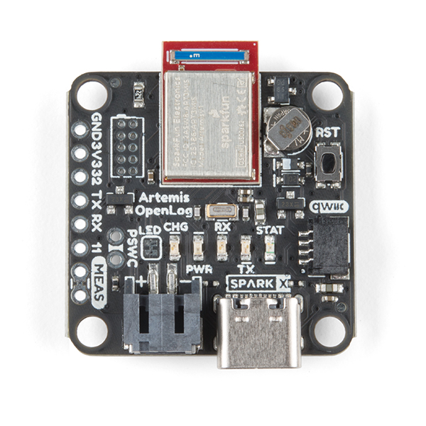
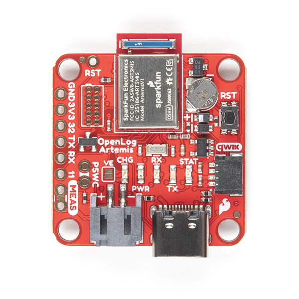
Giter VIP home page Giter VIP logo

sparkfun / openlog_artemis Goto Github PK

View Code? Open in Web Editor NEW
81.0 13.0 43.0 42.1 MB

The OpenLog Artemis is an open source datalogger the comes preprogrammed to automatically log IMU, GPS, serial data, and various pressure, humidity, and distance sensors. All without writing a single line of code!

Home Page: https://www.sparkfun.com/products/15846

License: Other

C++ 94.52% C 4.96% Dockerfile 0.51%

openlog_artemis's Introduction

SparkFun OpenLog Artemis

SparkFun OpenLog Artemis (DEV-16832) SparkX OpenLog Artemis (SPX-15846)

The OpenLog Artemis is an open source datalogger that comes preprogrammed to automatically log IMU, GPS, serial data, and various pressure, humidity, and distance sensors. All without writing a single line of code! OLA automatically detects, configures, and logs Qwiic sensors. OLA is designed for users who just need to capture a bunch of data to a CSV and get back to their larger project.

Included on every OpenLog Artemis is an IMU for built-in logging of triple axis accelerometer, gyro, and magnetometer. Whereas the original 9DOF Razor used the old MPU-9250, the OpenLog Artemis uses the latest ICM-20948 capable of nearly 1kHz logging of all 9 axis. We then took over a decade of experience with the original OpenLog and took it much farther. Simply power up OpenLog Artemis and all incoming serial data is automatically recorded to a log file. Baud rates up to 921600bps are supported! Additionally, based on feedback from users we've added an onboard RTC so that all data can be time stamped.

OpenLog Artemis is highly configurable over an easy to use serial interface. Simply plug in a USB C cable and open a terminal at 115200kbps. The logging output is automatically streamed to both the terminal and the microSD. Pressing any key will open the configuration menu.

The OpenLog Artemis automatically scans, detects, configures, and logs various Qwiic sensors plugged into the board (no soldering required!). Currently, auto-detection is supported on the following Qwiic products:

Very low power logging is supported. OpenLog Artemis can be configured to take readings at 500 times a second, or as slow as 1 reading every 24 hours. You choose! When there is more than 2 seconds between readings OLA will automatically power down itself and the sensors on the bus resulting in a sleep current of approximately 18uA. This means a normal 2Ah battery will enable logging for more than 4,000 days! OpenLog Artemis has built-in LiPo charging set at 450mA/hr.

New features are constantly being added so we’ve released an easy to use firmware upgrade tool. No need to install Arduino or a bunch of libraries, simply open the Artemis Firmware Upload GUI, load the latest OLA firmware, and add features to OpenLog Artemis as they come out! Full instructions are available in UPGRADE.md.

The OLA can be tailored to many different applications and we will be releasing custom versions of the firmware for those too:

Repository Contents

  • /Binaries - The binary files for the different versions of the OLA firmware.
  • /Firmware - The main sketch that runs OpenLog Artemis as well as a variety of sketches to test various sensor interfaces and power saving states.
  • /Hardware - Eagle files.

Documentation

  • Hookup Guide - hookup guide for the OLA.
  • UPGRADE.md - contains full instructions on how to upgrade the firmware on the OLA using the Artemis Firmware Upload GUI.
  • CONTRIBUTING.md - guidance on how to contribute to this library.
  • Installing an Arduino Library Guide - OLA includes a large number of libraries that will need to be installed before compiling will work.
  • ADDING_SENSORS.md - contains abbreviated instructions on how to add a new sensor to the OLA firmware. It's more of an aide-memoire really... Sorry about that.
  • COMPILE_BINARY.md - contains abbreviated instructions on how to compile the OLA firmware binary manually. It's also an aide-memoire really... Sorry about that.
  • SENSOR_UNITS.md - contains a summary of the units used for each sensor measurement.

Product Versions

License Information

This product is open source!

Various bits of the code have different licenses applied. Anything SparkFun wrote is beerware; if you see me (or any other SparkFun employee) at the local, and you've found our code helpful, please buy us a round!

Please use, reuse, and modify these files as you see fit. Please maintain attribution to SparkFun Electronics and release anything derivative under the same license.

Distributed as-is; no warranty is given.

  • Your friends at SparkFun.

openlog_artemis's People

Contributors

adamgarbo avatar bboyho avatar bouldervalleyhoney avatar gauteh avatar gigapod avatar github-actions[bot] avatar nseidle avatar paulzc avatar ryanneve avatar whipple63 avatar

Stargazers

 avatar  avatar  avatar  avatar  avatar  avatar  avatar  avatar  avatar  avatar  avatar  avatar  avatar  avatar  avatar  avatar  avatar  avatar  avatar  avatar  avatar  avatar  avatar  avatar  avatar  avatar  avatar  avatar  avatar  avatar  avatar  avatar  avatar  avatar  avatar  avatar  avatar  avatar  avatar  avatar  avatar  avatar  avatar  avatar  avatar  avatar  avatar  avatar  avatar  avatar  avatar  avatar  avatar  avatar  avatar  avatar  avatar  avatar  avatar  avatar  avatar  avatar  avatar  avatar  avatar  avatar  avatar  avatar  avatar  avatar  avatar  avatar  avatar  avatar  avatar  avatar  avatar  avatar  avatar  avatar  avatar

Watchers

 avatar  avatar  avatar  avatar  avatar  avatar  avatar  avatar  avatar  avatar  avatar  avatar  avatar

openlog_artemis's Issues

Suggestion: Battery Voltage Divider

@nseidle I'm curious, is adding a voltage divider to the OpenLog Artemis to measure battery voltage still a possibility for the next hardware revision?

As I've mentioned previously, this is an extremely valuable feature for any data logger to have (e.g. Adafruit M0 Adalogger) and it would be great to see it on the OLA.

Running the math quickly, it could look something like this:

Voltage input range: 2.5 - 6.0V (AP2112)
Analog input range: 0 - 2.0V
Resistor divider: 2MΩ/1MΩ
Voltage output range: 0.83 - 2.0V (1.167V)
Resolution: 0.0712 mV
Current draw: 2 μA @ 6.0V

The resistor values could be tweaked slightly (e.g. 5/2 MΩ) so as to not max out the analog input. A 0.1-1.0 μF capacitor would also be required.

Of course, the main question is where to stick it? Looking at the schematic, it looked like removing the PWR LED jumper would have opened up some real-estate, but it appears that the jumper has been repurposed.

Cheers!
Adam

Feature Request: Improve OLA time stamp resolution (when externally triggered).

Subject of the issue

Please consider improving the time stamp resolution of the OLA when it is externally triggered at pin 11. Presently the best time stamp resolution from the RTC is 10ms, please can this be improved to obtain a micro second time resolution.

Your workbench

  • microSD card? FAT
  • Using pin 11 to externally trigger on rising edge.
  • Version 1.6 firmware are you using?
  • Uses SparkFun GPS Breakout - NEO-M9N, U.FL (Qwiic) for initial synchronization of OLA RTC, all on board sensors disabled.
  • Powered by 1Ahr lipo battery.
  • Are there any additional details that may help us help you?

Steps to reproduce

Apply 2V rising edge logic signal to pin 11 of OLA

Expected behavior

OLA logs date and time when pin 11 is triggered

Actual behavior

Time stamp reaolution recorded is limited to 10ms.

SCD30 autodetection has problems

v1.2 OLA firmware, no MicroSD card, 10Hz output, SCD30 with no SEL connection.

SCD30 is usually autodetected correctly, but not always. It's most repeatable when SCD30 is first inserted/powered by OLA. After power-on, OLA can be reset and correctly IDs SCD30.

Unable to compile OpenLog_Artemis.ino

Subject of the issue

OpenLog_Artemis.ino is unable to compile locally. Appears to be due to a conflict between the following two libraries:

  • SparkFun_VL53L1X_4m_Laser_Distance_Sensor
  • SparkFun_High_Precision_Temperature_Sensor_TMP117_Qwiic

Your workbench

  • Working within Arduino IDE.
  • SparkFun Artemis Module board definition selected (is there an OLA definition?)

Steps to reproduce

  • Forked repository on GitHub, cloned locally through GitHub Desktop and modifying files directly.

Expected behaviour

  • Code would compile without issue.

Actual behaviour

In file included from /Users/adam/Documents/Arduino/libraries/SparkFun_VL53L1X_4m_Laser_Distance_Sensor/src/SparkFun_VL53L1X.h:31,
                 from /Users/adam/Documents/GitHub/OpenLog_Artemis/Firmware/OpenLog_Artemis/OpenLog_Artemis.ino:104:
/Users/adam/Documents/Arduino/libraries/SparkFun_VL53L1X_4m_Laser_Distance_Sensor/src/vl53l1x_class.h:58:30: error: expected unqualified-id before numeric constant
 #define SOFT_RESET           0x0000
                              ^~~~~~
/Users/adam/Documents/Arduino/libraries/SparkFun_High_Precision_Temperature_Sensor_TMP117_Qwiic/src/SparkFun_TMP117.h:39:11: note: in expansion of macro 'SOFT_RESET'
   uint8_t SOFT_RESET : 1;  // Software reset bit
           ^~~~~~~~~~

Commenting out all code relating to the VL53L1X allows the code to compile without issue.

Feature Request: Allow disabling of voltage regulator when entering deep sleep.

Request

There seem to be provisions to allow the OLA to turn the AP2112K regulator on and off. There's a split pad between D25 and the regulator's enable and pin 25 is defined as PIN_VREG_ENABLE.
It might be nice to have the option of disabling the 3v3 output when the OLA is in Deep Sleep. This would mean being powered by the RTC battery

Use case

My sampling rate is very low (every few minutes), but I want wireless access to the data, so I've got the OLA powering a BlueSMiRF module through the AP211K via the 3v3 pin. This will draw a lot of power, even when the OLA is in deep sleep if I can't turn it off.

Issues

How long will the RTC battery last when the OLA is in Deep Sleep? Looks like 14 uA from a 1mAhr battery.
How quickly does the RTC battery re-charge?
What happens if the RTC battery dies while the regulator is disabled?

In my case, I need some time when powering up to re-establish a Bluetooth connection, but I think I can do this by setting the Qwiic bus power up delay to a high enough number.

Firmware v15/v16 unable to export compiled Binary

Hi @nseidle,

Just a heads up that when attempting to export a compiled Binary from the v15/v16 firmware I run into the error:

/Users/adam/Documents/GitHub/OpenLog_Artemis/Firmware/OpenLog_Artemis/OpenLog_Artemis.ino: In function 'void enableCIPOpullUp()':
OpenLog_Artemis:552:11: error: 'MISO' was not declared in this scope
   padMode(MISO, cipoPinCfg, &retval);
           ^~~~
exit status 1
'MISO' was not declared in this scope

Is MISO missing a corresponding definition?

padMode(MISO, cipoPinCfg, &retval);

Cheers,
Adam

Create individual power-on delays for each sensor type

Some sensors have very long boot times and/or need to be powered constantly to run calculations between being queried for data. Powering down the Qwiic bus between sleeps causes these sensors to fail to perform as designed. SCD30 is a prime example but there are others.

Currently (v1.1 and above) Qwiic bus can be kept on between low power sleeps.

If a always-on device is detected, over ride the Qwiic bus power setting and stay on. If setting is over-written then display warning at initial power on banner.

Feature request: Option to set pin 32 wake up timer using RTC alarm

Subject of the issue

It's pretty easy to pull pin 32 low to put the OLA in Deep Sleep mode, but waking up the OLA is harder. you probably don't want to hold RST low. If you want to sample based on an environmental switch, it would be nice if there was a way to exit deep sleep without resetting.
This could be done by optionally setting a RTC wake alarm when pin 32 is pulled low. Just like when sleeping for long sampling rates, but for a longer period.
When the pin32 alarm wakes the OLA back up, if pin 32 is still low, it will go back to sleep again. Will interrupt be generated if it's low the entire time or would pin value need to be checked on startup?

Other considerations.

You'd probably want to clear the RTC alarm if the OLA wakes up early due to the RST button.

Example use case

If someone only wanted to sample when it was light out, they could hook a photo-switch up to pin 32 and have the pin32 sleep timeout set to 10 minutes. The OLA would sleep most of the night, waking every 10 minutes to see if pin 32 was still low. Come morning, it would stay awake, sampling at whatever rate desired.

Feature Request: Allow data collection rates faster than GPS

Subject of the issue

GPS modules like SAM-M8Q output data at 10Hz. When logging from those, all other data collection is slowed down to the same rate, no matter what the setting is

Your workbench

  • Attempting to log at 50 Hz, but limited to 10Hz b/c of GPS
  • Artemis OpenLog v1.17
  • How is OpenLog Artemis wired to your sensor(s)? Qwiic connector
  • How is everything being powered? Battery
  • Are there any additional details that may help us help you?
    From PaulZC in the forums -- "It would be possible to do this using the "autoPVT" function in the u-blox library. But it's not supported on the OLA at the moment..."

Steps to reproduce

Use GPS and attempt to log IMU at 50 Hz

Support multiple of a device through mux

Some I2C devices support only one I2C address but benefit greatly from multiple devices being read. The NAU7802 digital scale is probably at the top of this list.

Additionally, the OLA firmware does not support multiple of a device that does have multi-address support (for example, the LPS25HB). It would be nice to support both of these if possible.

Feature request: Output logs over Serial1 or USB

From forum

It would be great if USB could be used to move the CSV files from the OLA to my PC instead of only being used for configuration.

I interpret this as:

  • Create a menu option that allows the listing of logs, selection of a log, then outputting that log over USB and Serial1 (if that output is enabled - see request #32)

This opens a can of worms: We should probably implement an embedable command framework (AT command set?) akin to the original OpenLog for opening/editing/deleting logs. For now, let's just do a menu based system.

Firmware X04-v14_BETA Testing

Hi @PaulZC,

Putting the v14 firmware through its paces! Tests are being conducted with the OLA connected to the SparkFun SAM-M8Q board. Please see below for comments/suggestions/bugs.

General

  • I would suggest slightly increasing the timeout on the menus. This would help new users that may be unfamiliar with the various menu options.

9) Output Measurement Count: Enabled

  • The measurement count is a great addition. However, it appears to be missing a corresponding column title.

For example, even though enabled it wasn't included after output_Hz

  • rtcDate,rtcTime,aX,aY,aZ,gX,gY,gZ,mX,mY,mZ,imu_degC,gps_Date,gps_Time,gps_Lat,gps_Long,gps_Alt,gps_SIV,gps_FixType,gps_GroundSpeed,gps_Heading,gps_pDOP,output_Hz,

2) If sensor read time is greater than 2s, turn off Qwiic bus power: No

  • This menu option could be more clear. Is "sensor read time" the duration between samples?

Bug

  • If I disable the above menu option so the Qwiic bus power does not turn off between samples and increase the logging duration to 10 s, it appears that all measurements except for the GPS are removed after the first sample. Confirmed on the log file on the SD card. Please disregard if this is simply a quirk due to the way power is handled as we transition to the next hardware rev.
09:31:34.500 -> 18/10/2015,00:01:30.76,82.52,-219.73,-1120.61,11.05,0.48,-3.49,-25.65,35.10,-51.30,39.64,18/10/2015,00:00:33.000,0,0,0,0,0,0,0,9999,0.97,1,
09:31:45.667 -> 18/10/2015,00:01:41.94,18/10/2015,00:00:44.000,0,0,0,0,0,0,0,9999,0.16,2,
09:31:56.559 -> 18/10/2015,00:01:53.10,18/10/2015,00:00:55.000,0,0,0,0,0,0,0,9999,0.13,3,
09:32:07.473 -> 18/10/2015,00:02:04.01,18/10/2015,00:01:06.000,0,0,0,0,0,0,0,9999,0.12,4,
09:32:18.636 -> 18/10/2015,00:02:14.92,18/10/2015,00:01:17.000,0,0,0,0,0,0,0,9999,0.11,5,
09:32:29.557 -> 18/10/2015,00:02:26.08,18/10/2015,00:01:28.000,0,0,0,0,0,0,0,9999,0.11,6,
09:32:40.440 -> 18/10/2015,00:02:36.99,18/10/2015,00:01:39.000,0,0,0,0,0,0,0,9999,0.10,7,
09:32:51.603 -> 18/10/2015,00:02:47.90,18/10/2015,00:01:50.000,0,0,0,0,0,0,0,9999,0.10,8,
09:33:02.544 -> 18/10/2015,00:02:59.07,18/10/2015,00:02:01.000,0,0,0,0,0,0,0,9999,0.10,9,
09:33:13.448 -> 18/10/2015,00:03:09.98,18/10/2015,00:02:12.000,0,0,0,0,0,0,0,9999,0.10,10,

8) Synchronize RTC to GPS

It's great to see this functionality added to the OLA. While I haven't yet looked at the code that makes this feature possible, I would suggest adding a warning message if the OLA synchronizes the RTC with the GPS before a fix is able to be established (i.e. bad date/time).

Will keep testing!

Cheers,
Adam

readVin() before and after sleeping mode [BUG]

Subject of the issue

Reading Vin value throught readVin() function bug when OLA enter on sleep mode (after calling goToSleep() function).

Your workbench

I log IMU data at 5Hz at the beggining and print readVin() value. With just an USB alim, I have about 5.3V.

After 5s, I change the logging frequency to 0.2Hz (once per 5s), then OLA go to sleep mode, and when it wake up the voltage
of readVin() is about 0.2V.

Steps to reproduce

Connect OLA to USB, check readVin() value before and after sleep mode.

image

image

Expected behavior

Same value before and after sleep mode

Actual behavior

Strange value after sleep mode

Getting 224 WhoAmI on IMU (Apollo 2.0.4) - CIPO Issue?

Subject of the issue

I know it's a 2.0.4 issue again and we know 2.0.4 isn't mature yet, but hear me out! I'm attempting to get the basic 234 WhoAmI result from the ICM-20948 chip. I noticed on OLA on 1.2.1 it will read 224 if the CIPO is not enabled and will give the proper 234 result if the CIPO IS enabled. I'm assuming this is by design but have no idea why or how.

In 2.0.4, not matter how I configure the CIPO enable logic, I always get the 224 reading and cannot get past it. I'm posting the issue here as I'm sure you folks are much more aware of the inner workings of the 'why' on this board.

Does anyone have any ideas on where to go from here?

Your workbench

  • Simply plugged in to the USB port for power and loading firmware. I created a very simple sketch (pasted below), that is barebones, to run through the WhoAmI logic.
  • I've tested compiling on Windows, Linux and Mac with all of the same results.
  • Notes on using 2.0.4 - A couple of maintenance work items to get it to compile:
    • In order to download Apollo 2.0.4 you need to add the following URL to your 'Additonal Boards URL' list in Arduino preferences: https://raw.githubusercontent.com/sparkfun/Arduino_Apollo3/master/package_sparkfun_apollo3_index.json
    • Once downloaded you need to edit this file:../Arduino15/packages/SparkFun/hardware/apollo3/2.0.4/platform.txt. Replace includes.extra="-I{cores.path}/mbed-os/drivers/" with 'includes.extra='
    • You also need to take out the -MMD flag under in the following file: ..Arduino15/packages/SparkFun/hardware/apollo3/2.0.4/variants/SFE_ARTEMIS_ATP/mbed/.cxx-flags

Steps to reproduce

The sketch below is a fully working sketch. You should be able to put it in a sketch file and easily compile it under 1.2.1. With the little work above for 2.0.4 you should be able to get it to compile there just as easy without any changes to the sketch code.

Note: The CIPO enable logic will look a bit different just because I took out the middleman due to differences in Apollo versions (namely, no padMode). Although I took a more direct route, it's essentially the same path leading to the am_hal_gpio_pinconfig functon.

// OLA PINS
const byte PIN_IMU_POWER = 27;
const byte PIN_IMU_CHIP_SELECT = 44;

///////////////////////////
// Added variables here to satisfy requirements needed to test on 1.2.1 an 2.0.4 

#include "SPI.h"
#include "am_hal_gpio.h"

//2.0 doesn't have the NULL config so we make it here to match 1.2
const am_hal_gpio_pincfg_t AP3_GPIO_PINCFG_NULL_1_2 = 
    {
        .uFuncSel = 0,       
        .ePowerSw = 0,       
        .ePullup = 0,        
        .eDriveStrength = 0,
        .eGPOutcfg = 0,     
        .eGPInput = 0,      
        .eIntDir = 0,        
        .eGPRdZero = 0,     
        .uIOMnum = 0, 
        .uNCE = 0,    
        .eCEpol = 0,  
        .uRsvd22 = 0
};

const SPISettings spisettings = SPISettings(4000000, MSBFIRST, 0);


void setup() {
  Serial.begin(115200);
  SPI.begin();

///////////////////////////
// The OLA enableCIPOPullup logic, but in a format that compiles on both 1.2.1 and 2.0.4 of Apollo. 
// This logic still gives 224 if disabled and 234 if enabled. 

  am_hal_gpio_pincfg_t cipoPinCfg = AP3_GPIO_PINCFG_NULL_1_2;
  cipoPinCfg.uFuncSel = 1; //AM_HAL_PIN_6_M0MISO
  cipoPinCfg.eDriveStrength = 3; //AM_HAL_GPIO_PIN_DRIVESTRENGTH_12MA
  cipoPinCfg.eGPOutcfg = 1; //AM_HAL_GPIO_PIN_OUTCFG_PUSHPULL
  cipoPinCfg.uIOMnum = 0; //AP3_SPI_IOM
  cipoPinCfg.ePullup = 2; //AM_HAL_GPIO_PIN_PULLUP_1_5K
  am_hal_gpio_pinconfig(6, cipoPinCfg); //MISO = 6 -- Simply comment out this line to get a 224 on 1.2.1


///////////////////////////
// OLA Logic to power down and power up IMU just in case

  pinMode(PIN_IMU_CHIP_SELECT, OUTPUT);
  digitalWrite(PIN_IMU_CHIP_SELECT, HIGH);

  pinMode(PIN_IMU_POWER, OUTPUT);
  digitalWrite(PIN_IMU_POWER, LOW);

  delay(10);

  pinMode(PIN_IMU_POWER, OUTPUT);
  digitalWrite(PIN_IMU_POWER, HIGH);

  delay(100); //just a little delay just in case

///////////////////////////
// This is a SPI write that occurs in ICM Library to make sure we're in bank 0 for the WhoAmI check 

  uint8_t wBuff = (0 << 4) & 0x30;
  uint8_t wReg = 127;
  uint32_t wLen = 1; 
  SPI.beginTransaction(spisettings);
  SPI.transfer(0x00);
  SPI.endTransaction();

  digitalWrite(PIN_IMU_CHIP_SELECT, LOW);
  SPI.beginTransaction(spisettings);
  SPI.transfer(((wReg & 0x7F) | 0x00));
  for (uint32_t indi = 0; indi < wLen; indi++)
  {
      SPI.transfer(*(&wBuff + indi));
  }
  SPI.endTransaction();
  digitalWrite(PIN_IMU_CHIP_SELECT, HIGH);


  delay(100); //just a little delay just in case

///////////////////////////
// This is a SPI read that occurs in ICM Library for the WhoAmI check. If all goes well we should print out 234. This checks register 0 on bank 0
// that should always return 234. Not sure why it even pulls 224, regardless of any pullups enabled.  

  uint8_t rBuff = 0x00;
  uint8_t rReg = 0;
  uint32_t rLen = 1; 
  
  SPI.beginTransaction(spisettings);
  SPI.transfer(0x00);
  SPI.endTransaction();
  
  digitalWrite(PIN_IMU_CHIP_SELECT, LOW);
  SPI.beginTransaction(spisettings);
  SPI.transfer(((rReg & 0x7F) | 0x80));
  for (uint32_t indi = 0; indi < rLen; indi++)
  {
    *(&rBuff + indi) = SPI.transfer(0x00);
  }
  SPI.endTransaction();
  digitalWrite(PIN_IMU_CHIP_SELECT, HIGH);

///////////////////////////
// Print out the WhoAmI check results

  Serial.print("Who Am I (234 is correct, 224 is not): ");
  Serial.println(rBuff);
}


void loop() {
  delay(1000); //Just some placeholder delay since all the work we need is in Setup
}

Expected behavior

Expected to get 234 when CIPO is enabled and 224 when it is disabled on both, 1.2.1 and 2.0.4 Apollo.

Actual behavior

1.2.1 works as expected, but 2.0.4 always reads 224.

BLE enabled on the current hardware (OLA v1.18)

Just got a hold of this little gem of technology and was wondering if, at some point, the firmware can/will be updated to open up BLE and that the current hardware will be able to handle it or if it's going to require a new buy.

Thanks!

GPS time does not match GPS iTOW

Subject of the issue

When using a SAM-M8Q, the GPS time does not match the iTOW. While gps_iTOW proceeds monotonically, gps_TIME glitches backwards by a second every time the integer second rolls over. This is likely due to some kind of rounding error. See plot below

Your workbench

  • Are you using a microSD card? 16GB Hitachi FAT32
  • At what frequency are you logging? 5 Hz
  • What version of firmware are you using? Artemis OpenLog v1.17
  • How is OpenLog Artemis wired to your sensor(s)? Qwiic
  • How is everything being powered? Battery
  • Are there any additional details that may help us help you?

Steps to reproduce

Log all GPS values and rtcTime and some others at a speed of at least 5 Hz (maybe happens at lower speeds too?)

Expected behavior

gps_Time should be monotonic increasing unless Sparkfun is selling Flux Capacitors

Actual behavior

gps_Time Glitches backwards by 1 second at every integer second
Screenshot from 2020-10-31 18-29-31

Measurement count behaviour

Hi,

A super minor issue to look at on a rainy day.

I've observed that when logging data with the OpenLog Artemis with the measurement count option enabled 9) Output Measurement Count: Enabled, after the menu is accessed from the Serial Monitor and the OLA returns to logging, the measurement count is reset. This can result in log files with nonmonotonic counts.

The counter looks to be reset in the main menu. I wonder if there's a better spot for this to happen.

Also, when a new log file is created, should we be resting the measurement count? I'm of two minds.

Cheers,
Adam

09:49:52.422 -> rtcDate,rtcTime,VIN,count,
09:49:52.908 -> 2020-08-27,09:49:52.08,5.12,1,
09:49:53.906 -> 2020-08-27,09:49:53.08,5.12,2,
09:49:54.926 -> 2020-08-27,09:49:54.08,5.13,3,
09:49:55.914 -> 2020-08-27,09:49:55.08,5.13,4,
09:49:56.908 -> 2020-08-27,09:49:56.09,5.13,5,
09:49:57.151 -> 
09:49:57.151 -> Menu: Main Menu
09:49:57.151 -> 1) Configure Terminal Output
09:49:57.151 -> 2) Configure Time Stamp
09:49:57.185 -> 3) Configure IMU Logging
09:49:57.185 -> 4) Configure Serial Logging
09:49:57.185 -> 5) Configure Analog Logging
09:49:57.185 -> 6) Detect / Configure Attached Devices
09:49:57.185 -> 7) Configure Power Options
09:49:57.185 -> h) Print Sensor Helper Text (and return to logging)
09:49:57.185 -> r) Reset all settings to default
09:49:57.185 -> q) Quit: Close log files and power down
09:49:57.185 -> d) Debug Menu
09:49:57.185 -> x) Return to logging
09:49:58.133 -> 2020-08-27,09:49:57.28,5.11,1,
09:49:59.132 -> 2020-08-27,09:49:58.28,5.12,2,
09:50:00.123 -> 2020-08-27,09:49:59.28,5.12,3,
09:50:01.135 -> 2020-08-27,09:50:00.29,5.11,4,
09:50:02.119 -> 2020-08-27,09:50:01.29,5.11,5,

OpenLog Artemis - Data Logging Issues

Subject of the issue

I've encountered a number of issues when starting to work with the OpenLog Artemis and setting the log rate to longer values (i.e. 5-10 seconds). The two main issues are:

  1. OpenLog Artemis does not log data beyond the first observation.
  2. OpenLog Artemis does not power down after 2 seconds.

Your workbench

  • What development board or microcontroller are you using?
    • OpenLog Artemis
  • What version of hardware or breakout board are you using?
    • Firmware v1.1
  • How is OpenLog Artemis wired to your sensor(s)?
    • Directly via USB-C
  • How is everything being powered?
    • USB-C or 3.7V LiPo battery
  • Are there any additional details that may help us help you?
    • See below for raw data outputs.

Steps to reproduce

  • Connect to OpenLog Artemis over Serial and in the menu change "Set Log Rate in seconds between readings: " to 5 seconds (0.2 Hz) or 10 seconds (0.1 Hz)

Expected behaviour

  • OpenLog Artemis should log data every 5-10 seconds and provide a visual indication of samples being recorded via the STAT LED.
  • OpenLog Artemis should power down after 2 seconds of inactivity and have a sleep current of ~250 uA.

Actual behaviour

  • Only the first data sample is recorded to the microSD card. All subsequent data is not recorded.
  • Quiescent current does not decrease after 2 s of inactivity and remains at ~1 mA (SD card dependent).
  • When powering the OpenLog Artemis with either a 3.7V LiPo battery or 5V from USB-C, there is brief LED activity after the 45 second timeout but the STAT LED does not blink beyond that.

Raw data

Contents of dataLog00001.txt

SD card online
Data logging online
Serial logging online
IMU online
No sensors detected
rtcDate,rtcTime,aX,aY,aZ,gX,gY,gZ,mX,mY,mZ,imu_degC,output_Hz,
04/21/2020,09:08:15.28,-9.77,-19.04,-1000.00,-1.92,2.16,-1.11,-10.05,87.45,12.90,26.13,333.33,

Output of Serial Monitor:

09:07:26.486 -> 
09:07:26.660 -> Config file read complete
09:07:26.730 -> Artemis OpenLog v1.10
09:07:26.802 -> Created log file: dataLog00001.TXT
09:07:26.838 -> Created log file: serialLog00002.TXT
09:07:26.940 -> SD card online
09:07:26.940 -> Data logging online
09:07:26.940 -> Serial logging online
09:07:26.940 -> IMU online
09:07:26.977 -> No sensors detected
09:07:26.977 -> 
09:07:26.977 -> Menu: Main Menu
09:07:26.977 -> 1) Configure Terminal Output
09:07:26.977 -> 2) Configure Time Stamp
09:07:26.977 -> 3) Configure IMU Logging
09:07:26.977 -> 4) Configure Serial Logging
09:07:26.977 -> 5) Configure Analog Pin Logging
09:07:26.977 -> 6) Detect / Configure Attached Devices
09:07:26.977 -> r) Reset all settings to default
09:07:26.977 -> x) Return to logging
09:07:39.206 -> 
...
09:07:55.279 -> rtcDate,rtcTime,aX,aY,aZ,gX,gY,gZ,mX,mY,mZ,imu_degC,output_Hz,
09:07:55.279 -> 04/21/2020,09:08:15.28,-9.77,-19.04,-1000.00,-1.92,2.16,-1.11,-10.05,87.45,12.90,26.13,333.33,
09:08:00.608 -> 04/21/2020,09:08:20.62,-5.37,-30.76,-1016.60,-0.98,6.11,2.44,-11.10,87.60,14.70,25.07,666.67,
09:08:00.642 -> ⸮04/21/2020,09:08:25.95,-8.79,-18.07,-1020.51,-0.83,5.68,2.47,-12.15,86.70,12.90,25.31,1000.00,
09:08:05.958 -> ⸮04/21/2020,09:08:31.29,-4.39,-32.23,-1024.41,-1.15,-1.73,-6.09,-12.75,85.35,14.25,25.27,1333.33,
09:08:11.300 -> ⸮04/21/2020,09:08:36.63,-10.74,-25.88,-1008.30,-1.04,7.12,2.26,-11.10,85.80,12.75,25.22,1666.67,
09:08:16.644 -> ⸮04/21/2020,09:08:41.97,5.37,-24.41,-1013.67,-0.70,6.39,4.02,-10.20,85.05,7.05,24.98,2000.00,
09:08:22.001 -> ⸮04/21/2020,09:08:47.31,-5.86,-18.07,-1007.81,1.01,5.07,1.83,-9.90,86.10,7.05,25.12,2333.33,
09:08:27.334 -> ⸮04/21/2020,09:08:52.65,-11.72,-11.72,-1012.21,-1.65,3.35,3.34,-10.20,83.10,5.85,25.07,2666.67,
09:08:32.675 -> ⸮04/21/2020,09:08:57.98,-0.49,-25.88,-1001.46,0.75,-1.63,-3.56,-9.45,85.05,5.10,24.79,3000.00,
09:08:37.996 -> ⸮04/21/2020,09:09:03.32,-19.04,-14.16,-1006.84,-0.83,2.89,4.13,-9.45,82.05,4.35,25.22,3333.33,
09:08:43.352 -> ⸮04/21/2020,09:09:08.66,-26.86,-26.37,-1020.02,0.51,2.17,2.48,-9.45,83.55,2.40,24.88,3666.67,
09:08:48.674 -> ⸮04/21/2020,09:09:14.00,5.37,-34.18,-1010.25,1.62,3.50,1.60,-9.60,83.25,5.25,24.93,4000.00,
09:08:54.022 -> ⸮04/21/2020,09:09:19.34,-17.58,-26.37,-1015.14,0.21,2.69,1.62,-8.85,82.20,1.80,25.07,4333.33,
09:08:59.358 -> ⸮04/21/2020,09:09:24.68,-13.67,-36.13,-1007.32,-1.18,3.15,1.93,-9.00,84.60,5.10,24.93,4666.67,
09:09:04.678 -> ⸮04/21/2020,09:09:30.02,-12.21,-19.53,-1026.37,-1.53,2.41,1.16,-8.25,84.30,5.10,24.93,5000.00,
09:09:10.060 -> ⸮04/21/2020,09:09:35.37,-21.48,-21.00,-1017.09,-1.63,5.92,2.94,-9.90,82.80,5.10,25.22,5333.33,
09:09:15.393 -> ⸮04/21/2020,09:09:40.72,5.86,-17.58,-1009.28,-2.31,2.76,2.45,-8.85,83.70,4.95,24.93,5666.67,
09:09:20.743 -> ⸮04/21/2020,09:09:46.05,-16.11,-25.39,-1017.58,0.52,6.27,5.03,-10.05,84.45,4.20,24.98,6000.00,
09:09:26.080 -> ⸮04/21/2020,09:09:51.39,-5.37,-28.32,-1008.79,-0.09,1.74,2.60,-9.90,82.80,5.85,24.93,6333.33,
09:09:31.400 -> ⸮04/21/2020,09:09:56.73,-15.14,-23.44,-1026.86,-0.87,3.08,1.75,-9.00,83.10,5.10,24.88,6666.67,
09:09:36.729 -> ⸮04/21/2020,09:10:02.07,-2.93,-18.55,-1015.14,0.27,5.70,3.08,-8.40,84.00,4.20,24.79,7000.00,
09:09:42.084 -> ⸮04/21/2020,09:10:07.41,-20.51,-35.16,-1017.58,-2.23,2.76,1.23,-8.10,82.95,6.00,24.88,7333.33,
09:09:47.413 -> ⸮04/21/2020,09:10:12.75,-3.42,-30.27,-1015.62,-0.59,3.02,-0.26,-8.25,85.05,5.10,24.98,7666.67,
09:09:52.763 -> ⸮04/21/2020,09:10:18.09,-11.23,-16.60,-1015.14,-0.40,4.34,5.27,-9.00,83.55,6.60,24.93,8000.00,
09:09:58.087 -> ⸮04/21/2020,09:10:23.43,-7.81,-26.37,-1014.65,-0.15,2.03,4.09,-8.85,85.20,7.20,24.93,8333.33,
09:10:03.429 -> ⸮04/21/2020,09:10:28.76,0.00,-27.34,-1003.91,-0.98,3.43,4.76,-8.70,85.35,6.30,24.98,8666.67,
09:10:08.780 -> ⸮04/21/2020,09:10:34.10,0.98,-17.09,-1014.16,-1.11,2.90,1.11,-8.10,84.90,6.45,25.22,9000.00,
09:10:14.131 -> ⸮04/21/2020,09:10:39.44,-5.86,-25.39,-1010.74,0.41,2.49,1.32,-8.40,84.00,6.45,25.27,9333.33,
09:10:19.453 -> ⸮04/21/2020,09:10:44.78,-108.40,-6.35,-1166.50,-8.48,9.34,112.17,-21.60,74.40,8.85,24.88,9666.67,
09:10:24.795 -> ⸮

Update RTC commands to match Apollo3 Core v2.x

A quick reminder that we'll need to update the OpenLog Artemis' RTC setTime() commands in the firmware to reflect the new (standardized) order of hundredths, seconds, minutes, etc. that came in with v2.0 of the Apollo3 Core.

https://github.com/sparkfun/Arduino_Apollo3/blob/933524d33d3616ce1211d6ee191d1fbb7d5209cf/libraries/RTC/src/RTC.h#L28

I'll try to submit a PR to release_candidate to address this. Was the v17 binary compiled with v1.x or v2.x of the Apollo3 Core?

Cheers,
Adam

built in ICM init fails with v1.8 demo code

Subject of the issue

I need to modify the OpenLog code - but when I build it the ICM init() function fails "ICM-20948 failed to init"
Also found I had to fix a few things to even get it to compile

Your workbench

Sparkfun Apollo core 1.2.1, source code commit 57922e3, Board = "SparkFun RedBoard Artemis ATP"

Steps to reproduce

downloaded the needed libs, all normal files except:
zmodem_crc16.cpp
_//#include <avr/pgmspace.h>

#ifndef PROGMEM
#define PROGMEM
#endif_

zmodem_fixes.h
line 9 #define SERIAL_TX_BUFFER_SIZE 64

OpenLog_Artemis
int beginIMU()
Serial.print(F("ICM-20948 failed to init."));
Serial.printf("=%d\r\n",myICM.status);

_void enableCIPOpullUp() // fixed issue with MISO not defined
{
//Add CIPO pull-up
ap3_err_t retval = AP3_OK;
am_hal_gpio_pincfg_t cipoPinCfg = AP3_GPIO_DEFAULT_PINCFG;
cipoPinCfg.uFuncSel = AM_HAL_PIN_6_M0MISO;
cipoPinCfg.eDriveStrength = AM_HAL_GPIO_PIN_DRIVESTRENGTH_12MA;
cipoPinCfg.eGPOutcfg = AM_HAL_GPIO_PIN_OUTCFG_PUSHPULL;
cipoPinCfg.uIOMnum = AP3_SPI_IOM;
cipoPinCfg.ePullup = AM_HAL_GPIO_PIN_PULLUP_1_5K;

ap3_gpio_pad_t _padMOSI=0xff;
byte funcsel;

ap3_iom_pad_funcsel(AP3_SPI_IOM, AP3_IOM_SPI_MOSI, &_padMOSI, &funcsel);
padMode(_padMOSI, cipoPinCfg, &retval);

if (retval != AP3_OK)
printDebug("Setting CIPO padMode failed!");
}_

Expected behavior

normal demo should run with the ICM unit

Actual behavior

I added debug to give the error code returned:
ICM-20948 failed to init.=4

Feature request: Output instantaneous data over Serial1

From user comments

Can one stream the SD CSV file dataLog00000.TXT to a serial output port?

I would like to second the serial out (member 1274742's ) request. I have an application that uses a radio link and being able to stream the csv data over a serial link would be awesome.

I interpret this as:

  • An option to enable serial output of current readings to Serial1 at select baud rate.

OLA & GPS-RTK2 - Hanging at Boot

Subject of the issue

I've noticed some strange behaviour with the OpenLog Artemis and the GPS-RTK2 board while booting-up. It's frequently necessary to either re-open the Serial Monitor or hit the reset button in order for the OLA to actually boot up and start logging. When connecting the OLA via USB it appears to get stuck at reading the configuration file (shown below).

09:15:50.703 ->
09:15:50.740 -> Config file read complete (Freezes here)

When connecting the OLA to external power (i.e. battery), I have to hit the reset button 100% of the time to get the LEDs to start blinking and for logging to start.

Your workbench

  • What version of firmware are you using?
    • v1.3
    • Paul's GNSS Logger v1.1
  • How is OpenLog Artemis wired to your sensor(s)?
    • OLA + GPS-RTK2 using a single Qwiic connector
  • How is everything being powered?
    • USB-C or LiPo
  • Are there any additional details that may help us help you?
    • I've observed this behaviour on both of my OLA boards and firmware v1.1 to v1.3

Steps to reproduce

  • USB Issue
    • Connect OLA to GPS-RTK2
    • Open Serial Monitor and confirm OLA is logging properly
    • Unplug and reconnect USB without closing Serial Monitor
    • Observe OLA hang at "Config file read complete"
  • Battery Issue
    • Connect OLA to GPS-RTK2
    • Connect battery power
    • Observe no LED activity
    • Hit reset button and observe that LED activity begins

Expected behaviour

  • OLA should be able to boot properly without needing the Serial Monitor to be re-opened or the reset button to be pressed.

Actual behaviour

  • Hangs at boot-up

Units of logged data

Can you clarify what the units (and scales) are of the logged data?

It would be good if this was documented somewhere

Typo in IMU menu

Very low prio but:

  Serial.print(F("4) Toggle Magnotometer Logging: "));

Should be

  Serial.print(F("4) Toggle Magnetometer Logging: "));

Feature Request: Capability to Set ICM-20948 Full-Scale Range and Filtering Values

Subject of the issue

Please consider enabling the user to set the following programmable parameters of the ICM-20948 inertial measurement unit on the OLA board:
ICM-20948 Datasheet (https://cdn.sparkfun.com/assets/7/f/e/c/d/DS-000189-ICM-20948-v1.3.pdf) section and value:
10.2 GYRO_CONFIG_1, bit 5:3, GYRO_DLPFCFG[2:0], gyro low-pass filter configuration
10.2 GYRO_CONFIG_1, bit 2:1, GYRO_FS_SEL[1:0], gyro full-scale select
10.2 GYRO_CONFIG_1, bit 0, GYRO_FCHOICE, bypass or enable gyro DLPF (digital low-pass filter, I presume)
10.15 ACCEL-CONFIG, bit 5:3, ACCEL_DLPFCFG[2:0], accelerometer low-pass filter configuration
10.15 ACCEL-CONFIG, bit 2:1, ACCEL_FS_SEL[1:0], accelerometer full-scale select
10.15 ACCEL-CONFIG, bit 0, ACCEL_FCHOICE, bypass or enable accelerometer DLPF (digital low-pass filter, I presume)

My flying-machine application requires +/- 500 degrees/second gyro rates and +/- 16 g accelerations. I am taking data at 100 Hz, which aliases noise from a motor and propeller, hence the need to filter signals upstream of the sampling. Parameter values I would want are:
10.2 GYRO_CONFIG_1, bit 5:3, GYRO_DLPFCFG[2:0] = 1 or 2 or 3
10.2 GYRO_CONFIG_1, bit 2:1, GYRO_FS_SEL[1:0] = 01
10.2 GYRO_CONFIG_1, bit 0, GYRO_FCHOICE = 1
10.15 ACCEL-CONFIG, bit 5:3, ACCEL_DLPFCFG[2:0] = 1 or 2 or 3
10.15 ACCEL-CONFIG, bit 2:1, ACCEL_FS_SEL[1:0] = 11
10.15 ACCEL-CONFIG, bit 0, ACCEL_FCHOICE = 1

Thanks for considering this request. I think other folks would also like to be able to set these parameters.
.

Your workbench

  • Are you using a microSD card? Yes, 1 or 32 GB, FAT 32
  • At what frequency are you logging? 100 Hz
  • What version of firmware are you using? the latest
  • How is OpenLog Artemis wired to your sensor(s)? I'm currently only using the ICM-20948 that's on the board.
  • How is everything being powered? 5V regulated power aboard the airplane, USB for setting values on the ground.

Feature Request: Add IMU Euler Angles

Subject of the issue

Good day!
Please consider adding menu option to make OLA output “fused” IMU data in Euler Angles format:
Roll (x), Pitch (y) and Yaw (z)

Now OLA’s IMU outputs raw sensor data. By default it looks like this:
rtcDate,rtcTime,aX,aY,aZ,gX,gY,gZ,mX,mY,mZ,imu_degC,output_Hz,
Where
aX,aY,aZ – 3 axis accelerometer data (milli g)
gX,gY,gZ – 3 axis gyro data (Degrees per Second)
mX,mY,mZ – 3 axis magnetometer (micro Tesla)
https://github.com/sparkfun/OpenLog_Artemis/blob/release_candidate/SENSOR_UNITS.md#ICM-20948-IMU

Real world example:
01/02/2000,17:51:23.50,0.00,-45.41,1009.77,0.29,0.15,0.54,-0.90,-11.55,-37.95,28.56,19.42,
01/02/2000,17:51:23.60,3.91,-27.83,1007.81,-1.03,0.68,2.56,-0.45,-10.35,-36.15,28.17,14.78,
01/02/2000,17:51:23.70,6.35,-30.27,1019.04,2.79,0.41,0.69,-0.15,-10.05,-35.85,28.41,13.20,
I attach XLS file with more test data and some graphs (see second Excel sheet). I’ve put OLA on my desk, in a small box, and rotated it first over Y-axis, then over Z-axis, and then over X-axis. The test was not perfect, but it gives understanding what kind of data IMU outputs in relatively stationary conditions.
https://drive.google.com/file/d/1neTTJznOVbHkL8Lq28kz-av9kDZ-GDB4/view?usp=sharing

Why do we need roll, pitch, and yaw angles?
Because some applications by default use this format. For example, photogrammetry software (f.ex. Agisoft Metashape) accept only this format of photo orientation. With Euler angle output you will be able to attach OLA to a camera and get precise orientation data, which saves 40% project computation time (for large projects it can be days!).
Here is an example of DJI Mavic Mini drone orientation data. This is what I would like to receive from OLA:
https://drive.google.com/file/d/1klcJAtoMlrqTopzrh9Jx1AAVcEs6Agl5/view?usp=sharing

I’ve also found some information, maybe it will help:

https://cdn.sparkfun.com/assets/7/f/e/c/d/DS-000189-ICM-20948-v1.3.pdf
ICM-20948 datasheet says that IMU has integrated Digital Motion Processor (DMP) with following features:
Offloads computation of motion processing algorithms from the host processor. The DMP can be used to minimize power, simplify timing, simplify the software architecture, and save valuable MIPS on the host processor for use in applications.
• The DMP enables ultra-low power run-time and background calibration of the accelerometer, gyroscope, and compass, maintaining optimal performance of the sensor data for both physical and virtual sensors generated through sensor fusion. This enables the best user experience for all sensor enabled applications for the lifetime of the device.
• DMP features simplify the software architecture resulting in quicker time to market…”

https://invensense.tdk.com/developers/support-center-faq/
Euler angles are a representation of an angular frame, as are quaternions and rotation matrices.
Euler angles are a set of three angles, corresponding to pitch, roll, and yaw.
Euler angles may be constructed according to many conventions. The axes of and ordering of ordering of pitch, roll, and yaw vary by convention. The Embedded MotionApps Platform makes Euler angles available in the three most common conventions with MLGetEulerAnglesX, MLGetEulerAnglesY, and MLGetEulerAnglesZ. See the Embedded MotionApps Platform Functional Specification for specific details on the definition of these conventions…

What items 1 and 2 mean? I think they mean this:
• ICM-20948 is advanced IMU that has internal motion processor that can provide solution straight in Euler angle format
• ICM-20948 DMP constantly performs background self-calibration, no need to provide IMU calibration data manually
• InvenSense provide developers with ready to use getters to extract this data: MLGetEulerAnglesX, MLGetEulerAnglesY and MLGetEulerAnglesZ

IMHO, it is awesome, because normally to convert raw data to Euler angles (perform sensor fusion) we have to use some external MPU board (like Arduino) to receive sensor data, perform calculations, using one of existing algorithms (Mahony, Madgwick or other) and output solution. And this process normally requires sensor calibration procedure before getting actual measurements.
Here we have only to use getters and receive ready-to-use Euler angle data.

If working with ICM-20948 DMP is not an option, I kindly ask to consider adding IMU fusion capabilities to OLA’s MPU as it has plenty of power.

More reading about this topic:
sparkfun/SparkFun_ICM-20948_ArduinoLibrary#1 Here the DMP question seems to be solved. They get 40Hz yaw/pitch/roll over i2c. The code seems to contain a solution to parse the DMP output

https://github.com/micropython-IMU/micropython-fusion Here "fusion.py" file contains Madgwick algorithm implementation for IMU raw data fusion to Euler angles

https://github.com/arduino-libraries/MadgwickAHRS Arduino implementation of Madgwick algorithm

https://learn.adafruit.com/how-to-fuse-motion-sensor-data-into-ahrs-orientation-euler-quaternions?view=all
https://learn.adafruit.com/ahrs-for-adafruits-9-dof-10-dof-breakout/sensor-fusion-algorithms
https://github.com/PaulStoffregen/NXPMotionSense
https://www.pjrc.com/store/prop_shield.html

My workbench

  • Are you using a microSD card? – low latency (15ms) Sandisk Extreme, 32 GB, MicroSDHC, Class 10, UHS-I, U3. FAT32
  • At what frequency are you logging? - From 10Hz to 100Hz
  • What version of firmware are you using? - OpenLog_Artemis-V10-v17.bin
  • How is OpenLog Artemis wired to your sensor(s)? – Using internal IMU
  • How is everything being powered? - USB
  • Are there any additional details that may help us help you? – Described above

Thank you
Regards
Max.P

time between logs in seconds not accurate

It seems that the time between logs is done with a signed 8 bit integer. If I want to take a reading every 5 minutes I put in 300 seconds and it logs every 40 seconds.
Input 600 seconds and it logs every 80 seconds
Every input under 128 seconds is logged correctly. Anything over that is incorrect.

Currently using v1.3 of the firmware.

Logging dropouts

Subject of the issue

When logging IMU, 2 Analog voltages, RTC time, and GPS to an SD card, I get long logging dropouts, sometimes 3-4 seconds, and every now and then a measurement out of order

Your workbench

  • Are you using a microSD card? FAT32 16 GB
  • At what frequency are you logging? 10Hz
  • What version of firmware are you using? Artemis OpenLog v1.17
  • How is OpenLog Artemis wired to your sensor(s)? Qwiic
  • How is everything being powered? Battery
  • Are there any additional details that may help us help you?
    screenshot of log dropouts attached

Screenshot from 2020-10-31 14-00-04

Increase GNSS lat/lon logger precision to match ZED-F9P capabilities

The current logger reports latitude and longitude with 7 decimal places when receiving an NMEA GGA sentence, which is good for a little more than 1 cm. That's pretty good, but the dual-frequency receivers can do better under the right conditions, and when the NMEA HIGH_PREC config is set, the F9 receivers report DD MM.xxxxxxx (minutes with 7 decimal places), which is close to 9 digits of decimal degree precision.

Suggest that the code look for the number of places contained in the NMEA sentence and adjust the output precision accordingly.

I see that the program uses the SparkFun_Ublox_Arduino_Library but after grepping around in it I am still unable to figure out just where the NMEA sentence is actually being parsed; it doesn't seem to happen in either OpenLog_Artemis or that library. Maybe in yet another included library?

Thanks,
John

High gyro noise

Hello to the sparkfun / OpenLog_Artemis team.

I enjoy using your nice device, however is seems that the 'no motion' gyro readings are very high. I am receiving readings in the range of +-10 degrees / second. Based on the gyro datasheet I would be expecting noise approximately one order of magnitude smaller.

By manually trying a constant turn rate - the scale of the measurement readings seems correct.

Setup

Artemis OpenLog v1.6 (but same observed on previous versions)
Tested 4 different Artemis OpenLog boards
Bare board connected to USB

Reproduce

Results can be directly seen using arduino Serial plotter

Things that didn't help

  • compiling and flashing new Artemis OpenLog v1.6 using arduino toolchain
  • setting DLPFs using the gyro lib (filter does help a little but still

openlog_gyro

Feature Request: Serial Logging Timestamps

Subject of the issue

Is it possible to add an option to timestamp entries to the serial logfile? I am recording data coming from a separate microcontroller over serial, but would like the this data to be timestamped to align to the IMU data being collected by the OLA.

Your workbench

  • Are you using a microSD card? If so, what size? How is it formatted (FAT, FAT32, or exFat)?
    FAT32, 32GB card
  • At what frequency are you logging? For example, 10Hz, 1Hz, once every 5 seconds, etc.
    IMU logging at ~100 Hz, serial data coming in ~ 1 Hz
  • What version of firmware are you using? This is shown at boot, for example: "Artemis OpenLog v1.10"
    V1.8
  • How is OpenLog Artemis wired to your sensor(s)?
    Onboard IMU, serial line from peripheral microcontroller UART TX pin to OLA RX pin
  • How is everything being powered?
    OLA powered from usb-c, peripheral microcontroller via 3.3V pin on OLA
  • Are there any additional details that may help us help you?
    N/a

Steps to reproduce

Wire other device to provide serial data to OLA RX pin once per second. Viewing serial log file, there is no timestamp for each reading.

Expected behavior

Each line of serialLog****.TXT should have a timestamp attached to it that allows when the serial data was received to be aligned to when the IMU is sampled

Actual behavior

Serial log file contains no timestamps.

Feature request: Add support for SparkFun Triple Axis Accelerometer Breakout - MMA8452Q (Qwiic)

Subject of the issue

I would like to be able to log multiple accelerometers.
Use case: putting them on items that are coupled together to be able to assess vibration and natural frequencies.

Your workbench

1GB micro SD (FAT32)
10 Hz
1.8
wired to Mux abd 2 sensors via qwiic cables
usb-c through power bank

Steps to reproduce

Tell us how to reproduce this issue. Please post stripped down example code demonstrating your issue.

Expected behavior

Get accelerometer data for as a column in the .txt that is generated

Actual behavior

sensors are detected but not recognised. No data is coming through.

OLA Deletes OLA_settings.txt file

Subject of the issue

OLA deletes its own settings file on occasion, and ignores it on others. Possibly related to writing the file from a computer.

Your workbench

  • Are you using a microSD card? Hitachi 16GB FAT32
  • At what frequency are you logging? 10Hz
  • What version of firmware are you using? Artemis OpenLog v1.17
  • How is OpenLog Artemis wired to your sensor(s)? N/A
  • How is everything being powered? Battery
  • Are there any additional details that may help us help you?

Steps to reproduce

Put SD card in computer, confirm there is an OLA_settings.txt file there. Edit. Place back in OLA, let it run for a while, and then reread the card in the PC.

Expected behavior

File should not be deleted

Actual behavior

File is deleted

Fetch log records on demand over serial

I'm looking for a way to fetch recorded log records from OLA from another microcontroller.
The primary function of OLA is to offer datalogging for a variety of sensors. That is a very helpful building block for a larger application. However, if the larger application is running on another MCU, it would be very usefull if that MCU could access the recorded logs. The primary usecase I'm looking for is, that I want to use another MCU to send these recorded log files to a webserver for further processing.

That scenario would need features like: get current OLA timestamp, get list of files, fetch file, fetch file with n bytes offset, delete file ...
A suitable transport mechanism: serial?
This would also mean that the logged data would ideally be organised in a file structure that would fit this scenario, for example, create new file per sensor per hour, or per day ... The file structure could perhaps be a OLA config setting?

Feature Request: Add external trigger capability

Based on this request from @SignificantBat0:

I interpret this as:
Add an external sync/trigger feature. Start the OLA sensor read on the falling/rising edge of (e.g.) Pin 11.
Allow the user to enable/disable this feature (and select falling/rising edge) via the menus, like we do for stop logging.
(Why pin 11? Well, we use pin 32 for stop logging. The Tx/Rx pins could already be busy doing serial stuff. So, pin 11 is all that is left!)

MS8607 library references need to be updated to current library name

Master branch won't compile with current sparkfun MS8607 library due to incorrect name references in code

(V1.3)

To reproduce, clean install arduino IDE and install all libraries from links in Openlog_Artemis master branch. Compile will fail on mentions of MS8607_Library.h in various sketches.

Should be replaced with SparkFun_PHT_MS8607_Arduino_Library.h to allow compilation. (I'm not yet comfortable with submitting pull requests on github, hence why submitted here, sorry)

Feature request: OLA sleep and wake at specified times - OR - wake on motion (IMU interrupt)

Feature request: OLA SLEEP AND WAKE AT SPECIFIED TIMES

Hi!
I have a project in which we are logging data from the movement of patients using IMU. I'm using the on-board IMU.
I cannot have a battery larger than 1Ah since it will become heavy and big to carry around for the patients.
I need to somehow extend the battery life to 5 days. right now it only works for max 2 days. The patients suffer from movement problems so I cannot ask them to turn the boards on and off every day.

One solution that came to my mind and I think could be a good feature on OLA is to sleep and wake at specified times during a day. (using RTC).
For example, I need to log data from 10/19/2020 to 10/25/2020 from 9 AM to 3 PM each day, so the OLA should wake at 9 AM to log data and go to sleep at 3 PM to save battery, and repeat this every day until 10/25/2020. This could be a great feature for projects that there is no access to the board to turn it off.

Thanks for considering this! I have seen several guys in the forum looking for a way to extend battery life and this might be a solution for some of them.

Your workbench

  • Are you using a microSD card? yes a 32 GB Fat32
  • At what frequency are you logging? 100 Hz
  • What version of firmware are you using? v1.7
  • How is OpenLog Artemis wired to your sensor(s)? onboard IMU
  • How is everything being powered? 1Ah 3.7v lipo battery

Feature Request: Add Analog Voltage Threshold Trigger

I'm using the OLA to capture events and it would be great if there was an option to turn on event logging as a result of inputs on the analog inputs, more of a discrete datalog that would only log sample times on a logic low to high event or vice versa.

additionally, for another option it might be useful to only log RTC data at specific analog voltage levels. for ex, above 1.1 volts or less than .9 volts, ....

My specific use case is the first though, trying to only log RTC times for low to high events.

thanks

Recommend Projects

  • React photo React

    A declarative, efficient, and flexible JavaScript library for building user interfaces.

  • Vue.js photo Vue.js

    🖖 Vue.js is a progressive, incrementally-adoptable JavaScript framework for building UI on the web.

  • Typescript photo Typescript

    TypeScript is a superset of JavaScript that compiles to clean JavaScript output.

  • TensorFlow photo TensorFlow

    An Open Source Machine Learning Framework for Everyone

  • Django photo Django

    The Web framework for perfectionists with deadlines.

  • D3 photo D3

    Bring data to life with SVG, Canvas and HTML. 📊📈🎉

Recommend Topics

  • javascript

    JavaScript (JS) is a lightweight interpreted programming language with first-class functions.

  • web

    Some thing interesting about web. New door for the world.

  • server

    A server is a program made to process requests and deliver data to clients.

  • Machine learning

    Machine learning is a way of modeling and interpreting data that allows a piece of software to respond intelligently.

  • Game

    Some thing interesting about game, make everyone happy.

Recommend Org

  • Facebook photo Facebook

    We are working to build community through open source technology. NB: members must have two-factor auth.

  • Microsoft photo Microsoft

    Open source projects and samples from Microsoft.

  • Google photo Google

    Google ❤️ Open Source for everyone.

  • D3 photo D3

    Data-Driven Documents codes.